EP1006670A2 - Réseau sans fil - Google Patents
Réseau sans fil Download PDFInfo
- Publication number
- EP1006670A2 EP1006670A2 EP99203945A EP99203945A EP1006670A2 EP 1006670 A2 EP1006670 A2 EP 1006670A2 EP 99203945 A EP99203945 A EP 99203945A EP 99203945 A EP99203945 A EP 99203945A EP 1006670 A2 EP1006670 A2 EP 1006670A2
- Authority
- EP
- European Patent Office
- Prior art keywords
- sequence
- base station
- signaling
- terminal
- signaling sequence
- Prior art date
- Legal status (The legal status is an assumption and is not a legal conclusion. Google has not performed a legal analysis and makes no representation as to the accuracy of the status listed.)
- Granted
Links
Images


Classifications
-
- H—ELECTRICITY
- H04—ELECTRIC COMMUNICATION TECHNIQUE
- H04B—TRANSMISSION
- H04B1/00—Details of transmission systems, not covered by a single one of groups H04B3/00 - H04B13/00; Details of transmission systems not characterised by the medium used for transmission
- H04B1/69—Spread spectrum techniques
- H04B1/707—Spread spectrum techniques using direct sequence modulation
- H04B1/7073—Synchronisation aspects
- H04B1/7075—Synchronisation aspects with code phase acquisition
-
- H—ELECTRICITY
- H04—ELECTRIC COMMUNICATION TECHNIQUE
- H04B—TRANSMISSION
- H04B1/00—Details of transmission systems, not covered by a single one of groups H04B3/00 - H04B13/00; Details of transmission systems not characterised by the medium used for transmission
- H04B1/69—Spread spectrum techniques
- H04B1/707—Spread spectrum techniques using direct sequence modulation
-
- H—ELECTRICITY
- H04—ELECTRIC COMMUNICATION TECHNIQUE
- H04W—WIRELESS COMMUNICATION NETWORKS
- H04W52/00—Power management, e.g. Transmission Power Control [TPC] or power classes
- H04W52/04—Transmission power control [TPC]
- H04W52/38—TPC being performed in particular situations
- H04W52/50—TPC being performed in particular situations at the moment of starting communication in a multiple access environment
-
- H—ELECTRICITY
- H04—ELECTRIC COMMUNICATION TECHNIQUE
- H04B—TRANSMISSION
- H04B1/00—Details of transmission systems, not covered by a single one of groups H04B3/00 - H04B13/00; Details of transmission systems not characterised by the medium used for transmission
- H04B1/69—Spread spectrum techniques
- H04B1/707—Spread spectrum techniques using direct sequence modulation
- H04B1/709—Correlator structure
- H04B1/7093—Matched filter type
Definitions
- the invention relates to a wireless network with at least one Base station and several assigned terminals for the exchange of useful and Tax data.
- CDMA Code Division Multiplex Access
- the message package consists of a preamble part (Preamble part) and a data part (Data part).
- the Preamble part consists of 16 orthogonal symbols (Preamble Sequence / Preamble sequence) which is spread by a gold code (preamble code)
- the gold code contains 256 chip intervals he data part contains a field with an identification for the terminal, a field for identifying the requested service (transmission of short packets / short packet transmission, connection request for a dedicated user channel / dedicated-channel set-up etc.), an optional field for data packets ( Optional user packet) and a CRC field for error detection.
- a message packet received by a base station is delivered via a matched filter, a preamble correlator, a pulse detector (peak detector) to a circuit part which estimates the time course of the data part and which controls a RAKE circuit for evaluating the data part.
- a correlation-based pulse detection with subsequent message decoding is therefore used here.
- 80 random channels are available for the terminals assigned to a base station Available. These channels are identified by 16 different preamble codes and 5 different transmission times determined. Send two or more terminals over the same random channel, i.e. it will be the same preamble code and time of transmission selected, a collision arises and those emitted by the terminals The base station cannot correctly evaluate information. Such Collisions are particularly likely with high traffic loads.
- the invention has for its object to provide a wireless network a terminal in a different way with the signaling information assigned base station.
- the task is achieved through a wireless network of the type mentioned solved, that the base station for sending the start time of at least one signaling sequence at least one terminal is provided, that the base station has a device for correlating a received one Signaling sequence and for the detection of a received and correlated Signaling sequence resulting pulse contains and that a terminal for generating a signaling sequence by folding two Code sequences is provided.
- Under the wireless network according to the invention is a network with several To understand radio tents, in each of which a base station and several terminals Control and user data transmitted wirelessly.
- a wireless transmission is used for Transmission of information e.g. via radio, ultrasound or infrared paths.
- a terminal for the transmission of Request user data for a specific user channel from the assigned base station.
- a user channel can, for example, be a dedicated user channel (e.g. for voice transmission) either between base station and terminal or between two Terminals.
- the base station assigns the channels.
- from one terminal to one from the base station given signaling channel a request e.g. after a dedicated Transfer the useful channel.
- At least the starting time of one must be from the base station if necessary, previously known signaling sequence are communicated to the terminals. It is It is also possible that in addition to the start time of the terminals, one of several Signaling sequences is assigned.
- a signaling sequence is one Gold or Kasami sequence with good auto and cross correlation properties.
- the base station contains a device (e.g. a matched filter) in which a Correlation of the received signaling sequences is carried out.
- the one from the Correlation generated pulse is detected and assigned to a terminal.
- a collision is avoided and none Message decoding after correlation based pulse detection is performed, but the occurrence of the from the signaling sequence resulting pulse is regarded as a signaling request, a Signaling detection is particularly robust and robust when traffic is heavy be carried out faster than in the prior art.
- Detection window To detect a signaling sequence, depending on the Start time of the signaling sequence and from the channel shadows certain time range selected for pulse detection. Such a time range is called Detection window called. The length or duration and the start time of the Detection window must be selected so that pulse detection is possible. The Detection windows are smaller than the period of time from the prior art known message packages. So with the signaling according to the invention many terminals have a signaling request within a short time range drop.
- a terminal in a radio cell has after registration and synchronization for the transmission of a signaling sequence always the same start time based on a reference frame as long as the base station does not have this start time explicitly changes.
- a signaling channel is therefore permanent for a terminal busy. Because in the reference frame, which is of short duration (e.g. 10 ms), many such Start times can be included and since all terminals of a radio cell are the same Signaling sequence are used in the permanent assignment of a Start time and a signaling sequence to a terminal, only a little Network resources consumed.
- the signaling sequences of all terminals in a radio cell point different start times. It will be from any terminal in the simplest case uses the same signaling sequences.
- the signaling sequences can therefore partially overlap, since the length of a sequence is usually longer than that Is two consecutive start times.
- An advantage of the network according to the invention is also the security of the detection of a signaling request.
- a detectable pulse is generated practically every time a signaling sequence is sent. This is because of interference signals and channel noise can lead to artificial "pulses at the output of the matched filter. It is very unlikely that these will reduce the amplitude of the pulses at the output of the matched filter when an actually transmitted signaling sequence is received. In the worst case (for example in the case of faults), a false alarm is triggered if the amplitude of the noise or interference signal exceeds the detection threshold without a signaling sequence having been sent.
- Time intervals and the Barker sequence with 13 time intervals can be selected.
- the choice of these two code sequences is the autocorrelation property of the resulting signaling sequence after folding these two code sequences crucial.
- a base station contains two matched filters connected in series or one Matched filter and a downstream mis-matched filter to generate at least a pulse after receiving a signaling sequence of two convoluted Code sequences and a pulse detector.
- the pulse detector is during one certain detection window, its start time and duration by the Channel properties and the start time of a signaling sequence is determined, for the detection of at least one pulse assigned to a terminal is provided.
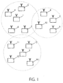
- Fig. 1 is a wireless network, e.g. Radio network, with several base stations 1 to 3 and several terminals 4 to 14.
- a base station 1 to 3 are assigned to certain terminals 4 to 14.
- base station 1 terminals 4 to 7 are base station 2 terminals 8 to 10 and the base station 3 assigned to the terminals 11 to 14.
- a tax data exchange takes place at least between the base station and the terminals.
- An exchange of user data can be between the base station and the terminals as well as directly between the Terminals are carried out.
- Terminals 4 to 14 are in usually mobile stations controlled by a permanently installed base station 1 to 3 become.
- a base station 1 to 3 can, however, also be movable or mobile his.
- the CDMA method which is a special code spreading method
- binary information (data signal) originating from a user is modulated with a different code sequence in each case.
- a code sequence consists of a pseudo-random square-wave signal (pseudo noise code), the rate of which, also called the chip rate, is generally significantly higher than that of the binary information.
- the duration of a square-wave pulse of the pseudo-random square-wave signal is referred to as the chip interval T C. 1 / T C is the chip rate.
- the base stations are assigned certain radio cells in which the data traffic with the terminals located in the radio cell. Is moving a terminal from one radio cell to another radio cell, according to certain The assignment of the terminal from one base station to another. This terminal can be used simultaneously when changing from one to another Exchange the radio cell with the base stations of the two radio cells. this will referred to as soft handover.
- a radio cell is dashed in Fig. 1 by a drawn circle indicated.
- User data and control data between at least one terminal and a base station are transmitted via channels specified by the base station.
- the radio link from the base station to the terminals is used as a downlink and from the terminals to Base station called uplink.
- uplink data from the Base station to the terminals and via uplink channels from terminals to the base station Posted.
- a downlink control channel that uses can be provided is sent to everyone from the base station to control data before establishing a connection Distribute terminals.
- Such a channel is called a downlink distribution control channel (broadcast control channel).
- For the transmission of tax data in front of a Connection establishment from a terminal to the base station can, for example, be one of uplink control channel assigned to the base station can be used, but also on the can access other terminals.
- An uplink channel used by several or all Terminals can be used as a common uplink channel (common uplink channel).
- a connection e.g. between a terminal and the base station receive user data via a downlink and an uplink user channel transfer.
- peer-to-peer user channels For the direct transmission of user data between two terminals Used channels that are referred to as peer-to-peer user channels. Channels that only built between a transmitter and a receiver are considered dedicated Called channels.
- a user channel is a dedicated channel that is assigned by one dedicated control channel for the transmission of connection-specific control data can be accompanied.
- a channel is divided by a frequency range, a time range and e.g. in the CDMA process determined by a spreading code. So that user data between Base station and a terminal can be replaced, it is necessary that the terminal is synchronized with the base station.
- GSM Global System for Mobile communication
- a combination of FDMA and TDMA methods is used that after the Determination of a suitable frequency range based on specified parameters temporal position of a frame is determined (frame synchronization), with its Help the time sequence for the transmission of data takes place.
- frame Global System for Mobile communication
- Such a framework is always for data synchronization of terminals and base station with TDMA, FDMA and CDMA procedures required.
- Such a frame can be different Contain sub or subframes or with several other successive ones Form a super frame. For reasons of simplification, the following is: assume a frame called the reference frame.
- all terminals must be on the Base station with the help of pulses emitted by the base station be synchronized.
- no code spreading procedure e.g. CDMA procedure
- TDMA method e.g. a TDMA method
- the pulse duration corresponds to one Chip interval.
- One bit interval corresponds to several chip intervals.
- For Frame synchronization is the transmission of a special pulse sequence through the Base station required. The start time of the pulse sequence corresponds to that Start time of a frame.
- a terminal e.g. one of the terminals 4 to 7 in Fig. 1
- this must for transmission a user channel for a downlink and an uplink connection or a peer-to-peer user channel from the associated base station (e.g. base station 1 in Fig. 1) to Will be provided.
- the base station e.g. base station 1 in Fig. 1
- the assigned terminals e.g. terminals 4 to 7
- a Downlink broadcast control channel during a free selectable frame control data.
- These tax data inform the terminals about at what point in time (sequence start time) in relation to the frame can send a special signaling sequence.
- One from a terminal signaling sequence sent is a pseudo-random square wave signal and indicates that this terminal requests a user channel.
- Each terminal is therefore Transmission of a signaling sequence from the base station an uplink signaling channel assigned, transmitted over the signaling sequences become.
- the Base station the assignment of the signaling sequence and the sequence start time Carry out only once for each terminal. For example happen during the registration of a terminal with the associated base station.
- the assignment of the sequence start times can also - as explained below - depending on the different channel properties of the Connections are made between the base station and terminals.
- a signaling channel is in the invention by the specific signaling sequence and their Start time realized.
- All terminals assigned to a base station send the same Signaling sequence but at different times (sequence start times) out. Consequently, different base stations have their assigned ones or registered terminals to different signaling sequences. Here is however, it is sufficient if only the neighboring base stations each have different signaling sequences. If a terminal, for example in the case of a transition from one radio cell to another with two base stations is registered, this sends out the signaling sequence which the base station specifies from which a user channel is requested.
- a base station contains a single matched filter and a downstream pulse detector for the detection of the signaling sequences emitted by the terminals.
- the matched filter is clocked at a clock rate that is at least equal to the maximum chip rate if code spreading is used, or the maximum bit rate if no code spreading is used.
- Signaling sequences which have a good autocorrelation property are transmitted from the terminals. This means that the pulses resulting at the output of the matched filter from successive signaling sequences of different terminals can be clearly detected by the pulse detector within a detection window.
- the choice of the clock rate depending on the maximum chip rate or bit rate and a signaling sequence with good autocorrelation properties enables the successive signaling sequences to have a minimal time interval between their start times.
- the signaling sequence should have a good cross-correlation property, ie the correlation to other signals transmitted in the network should be low.
- the other signals transmitted in the network and received by the matched filter are interpreted by the pulse detector as a negligible noise signal
- the signaling sequences of other circuit elements in the base station, which process the other signals transmitted in the network are interpreted as negligible noise or interference signals .
- Such a signaling sequence with good auto and cross correlation properties is, for example, that from the book JG Proakis: Digital Communications by JG Proakis, Third Edition, McGraw-Hill International Editions, 1995, pages 724 to 729 "known sequence of Gold and Kasami.
- the pulses resulting at the output of the matched filter are a measure of that Energy of the signaling sequences.
- the length and unlike the others signals to be transmitted determined low amplitude of the signaling sequence consequently the pulse height at the output of the matched filter.
- the sequence start time of a signaling sequence should be from the base station be determined that the matched filter in the base station one pulse after the Detection of a signaling sequence of a terminal assigned to it in one predefined detection window generated.
- This detection window has the duration or Length * on.
- the signaling sequences can be set at any sequence start time send out.
- a sequence start time is when a Pulse connected at the output of the matched filter.
- the detection starts after Transmission of a signaling sequence and one by the channel property of one Connection between at least one terminal and one base station Delay.
- the physical parameters of a are used as a channel property Called channel.
- a channel property results, for example, from the distance between terminal and base station.
- the pulse detector differently wide detection windows used for the different terminals.
- the for the sake of simplicity, a uniform width of the detection window is chosen here.
- the consequence of any detection window of the duration * is in relation to the Reference frame of length FR shown in Fig. 2.
- the matched filter creates from a received signaling sequence usually a pulse sequence with a Main pulse and several often symmetrically distributed around the main pulse Secondary impulses. The amplitude of the secondary impulses is regularly smaller than that Main pulse amplitude.
- the different main impulses generated by the matched filter must be one have sufficient distance (guard time) so that the at the exit of the Matched filters appearing, through the channel distorted pulse train of the different terminals do not overlap so that no clear detection becomes possible. With a certain overlap, the base station can use the pulses not clearly assign to a terminal.
- the width or duration * of the Detection window must therefore be at least equal to the main pulse width results without channel influence, and an additional channel-dependent safety interval his. This also results in the distance from successive, the same Signaling sequences. However, there must be no consideration of the time intervals are taken from two different signaling sequences, which by different base stations originate because of a low correlation Matched filter downstream pulse detector a signaling sequence other base station or radio zone detected as non-distracting noise.
- an optimized interval between the sequence start times can be transmitted be provided. This means that the width of the Detection window depending on the channel shadow between one Terminal and the base station is determined.
- Another simpler according to the invention Possibility to be realized is that the signaling sequences are successive be sent at a constant distance. When determining the the worst channel properties have to be considered at a constant distance. 3 shows the continuously successive detection windows with respect to the Reference frame of length FR, which follows as a result of a given constant signaling sequences emitted.
- FIG. 4 shows two exemplary signaling sequences S 1 and S 2 , which have the sequence duration or sequence length L 1 and L 2 .
- the detection process or the detection window of length * starts.
- a main pulse and secondary pulses assigned to a signaling sequence appear in such a detection window.
- the length * of the detection window is determined in particular by three factors (channel switching) certainly.
- the terminals are usually at different distances from the base station. This leads to different propagation delays in the signaling sequences transmitted by the terminals.
- the propagation delay between the terminal MT i and the base station B should be p i and the length of the signaling sequence should be L. If the base station expects a pulse for the terminal MT 1 at the output of the matched filter at the time t i , it instructs the terminal MT 1 to transmit the signaling sequence at the time t 1 - p 1 - L to start.
- the pulse at the output of the matched filter is subject to inaccuracy. This inaccuracy in the estimation of the propagation delay p i must be compensated for by a sufficiently long detection window *. If the maximum inaccuracy in the estimate is j for all terminals, the detection window must be larger than j.
- the data between a terminal and a base station is usually not only transmitted over one radio path but over several (multiple propagation). Due to reflection and diffraction effects, this runs from one terminal to the other Base station signal transmitted via different routes and resulting from it Resulting signals running in different ways are received by the base station received at different times.
- This further main impulses arise at the output of the matched filter by signals that originated from the multiple spreading and that around the actual Main pulse are grouped.
- the actual main pulse arises at the output of the Matched filters from the actual signaling sequence received.
- the length * of the detection window should be greater than a window of length w, which contains the actual main pulse and the other main pulses. It is notices that even without multiple propagation at the output of the matched filter it does not only an actual main impulse, but also secondary impulses appear. The However, the amplitude of the secondary pulses is much smaller than the amplitude of the Main impulse due to the good autocorrelation properties described above.
- the autocorrelation property of the signaling sequence is the measure of the width of the main pulse and the minima and maxima of the secondary pulses at the output of the Matched filters (without taking channel properties into account).
- a gold or Kasami sequence is - as mentioned above - the main impulse at the output of the matched filter approximately equal to the energy of the signaling sequence.
- the amplitude of the The main pulse is much larger than that of the secondary pulses.
- the energy of the Signaling sequence is thus determined by its amplitude and duration or Length.
- the Signaling sequence e.g. Gold or Kasami sequence
- one against the other Signals have significantly lower amplitude.
- the Signaling sequence be long enough. This extends the Detection duration of a signaling sequence and thus the assignment of User channels of the base station to the terminal (extension of the signaling time), which sent a signaling sequence. So the length affects one Signaling sequence both the autocorrelation property of the Signaling sequence as well as the signaling time. If for a given Signaling sequence the autocorrelation function within a time interval q is sufficiently large, * must be greater than q.
- the duration * of the detection window is dimensioned such that only a single signaling sequence can be detected.
- a base station receives binary information or 1-bit information.
- This binary information indicates whether a terminal which has sent out the signaling sequence requests a new user channel (pulse at the output of the matched filter during the duration of the detection window) or no user channel (pulse at the output of the matched filter during the duration of the Detection window not available).
- the following is the expansion of the transmission from 1-bit to n-bit information (n> 1, n is an integer).
- a terminal sends out the same signaling sequence not once but several times in succession per reference frame in order to provide the base station with n-bit information.
- This expansion from 1-bit to n-bit information is achieved by extending the detection window by increasing the duration or length of the detection window by a factor of n for each terminal concerned. In this way, n signaling sequences of a terminal can be detected during the occurrence of the n-times enlarged detection window.
- the terminal which transmits n-bit information (signaling data), uses the same signaling sequences, the starting times of which are shifted by the value *. A transmitted signaling sequence then gives, for example, one 1 "and an unsent signaling sequence 0 ".
- a first group G1 of pulses is assigned to signaling sequences of a first terminal and a second group G2 of pulses is assigned to signaling sequences of a second terminal.
- the 7-bit information results from the first group G1 1100111 "and the information from the second group G2 0100101 ".
- the information 000 " which corresponds to a non-transmission of three successive signaling sequences, mean that the terminal does not request a user channel.
- the information 001 " can mean that the terminal requests an 8 kbit / s user channel.
- the information is provided by two signaling sequences that are not transmitted and one transmitted 001 ".
- the desire for a 64 kbit / s user channel of a terminal can be based on the information 010 "and the desire for a 144 kbit / s user channel of a terminal can be explained by the information 011 "can be expressed.
- the matched filter in the base station is for receiving both 1-bit and also provided by n-bit information since the same in both cases Signaling sequence is received. It only differs in the two cases the post-processing of the pulses detected by the matched filter.
- information processing is based on the duration * for the detection of a Signaling sequence and in the second case after the duration * for the detection of n Signaling sequences carried out.
- the Number of signaling channels of a base station when using a single one Signaling sequence is limited to the value FR / *, where FR is the length of the Reference frame and * is the length of a detection window.
- FR is the length of the Reference frame
- * is the length of a detection window.
- each detection window is the same length and has the length *.
- 120 terminals in the radio cell that send a signaling sequence want it is not possible that all of these 120 terminals are the same Use signaling sequence. Therefore e.g. 60 terminals a first and the Send a second signaling sequence to another 60 terminals, which is then sent by two different matched filters can be detected in the base station. It is still mentioned that the sequence start times of the different signaling sequences are independent of each other, i.e. not coordinated with each other is required. Only the start times of the same signaling sequences have to be coordinated.
- a terminal can use a signaling sequence with a emit small amplitudes that are normally good enough from one Base station can be received. If this signaling sequence from the assigned base station has been detected, the base station notifies the terminal a requested channel. After receiving the message, the terminal does not send any further signaling sequence more.
- the terminal sends a signaling sequence after a does not receive any feedback from the assigned base station for a predetermined time a new signaling sequence with a higher amplitude. If that Terminal did not make an assignment from the base station within the specified time another signaling sequence with an increased amplitude is obtained sent out. This process is repeated until a predetermined, maximum Value for the amplitude has been reached or the terminal previously a Received channel assignment from the base station.
- This problem with increasing the error alarm rate can be solved in that the base station does not immediately assign a channel to a terminal after detection of a signaling sequence, but in that the base station waits for several signaling sequences (h signaling sequences with h> 1) consecutive frames in g (g> 1) have been detected in the detection window provided. If the error alarm rate for a detected pulse in the base station is p, then the error alarm rate for h successive detected pulses is reduced to p h .
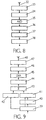
- 6 to 9 is a receiver (Fig. 6) and a transmitter (Fig. 7) a base station and a receiver (Fig. 8) and a transmitter (Fig. 9) of a terminal.
- the block diagram shown in FIG. 6 of a receiver of a base station contains as known elements (e.g. from the GSM mobile radio system or a CDMA system) an antenna 15, a high frequency block 16, an intermediate frequency block 17, one Analog-digital Unisetzer 18 a demodulator 19 and a block 20 which e.g. the Switching functions channel demultiplexing, deinterleaving, channel decoding and at Using a CDMA system also performs de-spreading.
- the control and useful signals present in the baseband become a channel access control block 23 supplied, the various signals to the corresponding Processing units such as forwarding to a switching center.
- a matched filter 21 is in the receiver of the base station inserted, which then checks the received signals whether a Signaling sequence is present. Is a signaling sequence during the expected time period (detection window) has been detected, i.e. at least it will generates a pulse, this is determined by a subsequent pulse detector 22 and the channel access control block 23, which e.g. can be a processor.
- the Channel access control block 23 does not forward this message to subordinate ones here further control elements shown, which are then e.g. by means of generated Assign control data via the transmitter of the base station to the user channel.
- the duration or length * of the detection window can be fixed and determined, for example, by measurements before the normal operation of the network have been. It is also possible to set the duration * of the detection window for each terminal to be determined individually during operation.
- the duration * of the detection window for a specific signaling sequence and a terminal is in this case of a control element not shown here, the pulse detector after Evaluation of measurement results supplied.
- the GSM mobile radio system for example, the distance between a base station and a terminal the signals received from the terminal are evaluated in the base station.
- the information processing of those determined by the pulse detector 22 by the matched filter 21 generated pulses is carried out in the channel access control block 23.
- the channel access control block 23 states that there is a request from the terminal for a user channel. Out this request and requests from other terminals and taking into account the existing ones Connections or the assigning user channels, decides not one Control shown after receiving the request from the channel access control block 23 whether a user channel can be made available to the requesting terminal. If it is possible to assign a user channel, this user channel is determined and after processing in the base station transmitter (Fig. 7) via a downlink distribution control channel fed to the terminal.
- the base station transmitter shown in Fig. 7 also contains a channel access control block 24, which receives data from various sources 25.
- a source can be, for example, a switching center that supplies useful data, or a Control element which supplies control data.
- these Control data Information about a user channel to be used for a terminal contain which previously uses a signaling sequence a user channel has requested.
- the block 26 following the control block 24 carries out e.g. the Switching functions channel coding, interleaving, channel multiplex and when in use of a CDMA system also by spreading.
- the output signal of the Blocks 26 is a modulator 27, a digital-to-analog converter 28, a Intermediate frequency block 29 and a high-frequency block 30 to an antenna 31 given. All elements 25 to 31 can be made from existing mobile radio systems known elements.
- FIG. 8 A block diagram of a receiver of a terminal is shown in FIG. 8.
- This receiver contains as for example from the GSM mobile radio system or a CDMA system known elements an antenna 32, a radio frequency block 33, an intermediate frequency block 34, an analog-to-digital converter 35, a demodulator 36, one Block 37 with various functions and a channel access control block 38 which Control and user data to different sinks (e.g. low-frequency switching for Conversion of user data into voice data) delivers.
- Block 37 is for example for the switching functions channel demultiplexing, deinterleaving, channel decoding and at Use of a CDMA system responsible for the despreading.
- the Channel access control block 38 evaluates certain channels relevant to the terminal, such as e.g. a user channel or a downlink distribution control channel.
- This Information is sent to certain other circuit elements not shown here headed in the terminal.
- the terminal contains the associated block diagram in FIG. 9 a channel access control block 39 that controls channel access is also shown.
- the channel access control block 39 provides a block 42 which e.g. the switching functions Channel coding, interleaving, channel multiplexing and when using a CDMA system also performs a spread.
- the channel access control block 39 a time control element 40 at the start time of a signaling sequence.
- the channel access control block 39 receives useful and control data from various Swell.
- a source can be, for example, a low-frequency circuit that Provides voice data as useful data, or a control element, which control data feeds. For example, this control data can provide information about the start time a signaling sequence.
- the timing element 40 provides time stamps to one Generator 41 for generating a signaling sequence.
- the timestamps can for example the start and end times of rectangular pulses of the Signaling sequence.
- the generator contains a memory for storage different signaling sequences.
- the signaling sequence to be sent is selected by the channel access control block. In the memory of the generator 41 If necessary, signaling sequences can be written.
- the Generator 41 and the timing element 40 are activated after receiving the information the signaling sequence to be used and the start time of the Signaling sequence initialized. If no change in the signaling sequence and / or the start time from the assigned base station is one further initialization of generator 41 and time control element 40 is not required.
- the user and control data processed in block 42 become one Superposition circuit 43 supplied, which still the output signals of the generator 41st receives.
- the output signal output from the superimposition circuit 43 is over a modulator 44, a digital-to-analog converter 45, an intermediate frequency block 46 transmitted to a high-frequency block 47, which by means of an antenna 48 Radiofrequency block formed signals emits.
- the length and the amplitude of a signaling sequence each be as low as possible to avoid interference with other signals and reduce the detection time.
- an increased error alarm rate FAR
- a failure alarm rate is equal to the probability that the pulse detector downstream of the matched filter has a pulse detected even though no signaling sequence has been sent.
- Signaling sequence with 4096 chip intervals can be selected.
- the generation of Signaling sequences with such a length means a great deal of effort in Comparison with a gold sequence with 256 chip intervals as signaling sequence, because larger memories are needed in the terminal and the base station and because especially the matched filter in the base station becomes too complex.
- the signaling sequences in a terminal generated at least two steps. In a first step, a first code sequence generated, which is linked in a second step with a second code sequence. The Concatenation of both code sequences results in the signaling sequence. Through the The matched filter can then be implemented in two stages in the base station, which leads to a reduction in complexity.
- a Barker sequence with 13 time intervals can be used as the first code sequence and a gold sequence with 256 time intervals is used as the second code sequence become.
- the chaining results in a signaling sequence with 3328 Chip intervals.
- the chaining makes practically the good ones Autocorrelation properties of the gold sequence consisting of 256 time intervals passed on to the chained signaling sequence. This is because the Barker sequence has an optimal aperiodic autocorrelation function and this hardly changed the good auto-correlation properties of the gold sequence become.
- the concatenation between the two code sequences can be expressed as follows.
- the first code sequence which is a Barker sequence with 13 time intervals
- the second code sequence which is a Gold sequence with 256 time intervals
- T should be the duration of a chip interval.
- the concatenation of these two code sequences b (t) and g (t) can be mathematically expressed as convolution b (t) * g (t). Such convolution is equivalent to spreading each sample of the Barker sequence with the Gold sequence.
- the generation of such a signaling sequence in two steps from a Barker and a gold sequence can be generated in the generator 41 of the transmitter shown in FIG of a terminal.
- the generator 41 spreads a Barker sequence with the gold sequence and thus ran a signaling sequence with 3328 Chip intervals to the superimposition circuit 43.
- the second matched filter To detect such a signaling sequence from two code sequences are in a base station requires two matched filters connected in series.
- the The output signal of the second matched filter is fed to the pulse detector.
- the first matched filter is connected to the second code sequence (Gold sequence with 256 Time intervals) and the second matched filter to the first code sequence (Barker sequence with 13 time intervals).
- the second matched filter delivers Are there a signaling sequence whose autocorrelation function, which the Pulse detector is supplied to find the main pulse.
- the matched filter 21 shown in FIG. 6 must include another second matched filter be expanded to include a signaling sequence with two code sequences detect.
- the first matched filter 21 must be connected to the second code sequence and the second matched filter, not shown in FIG. 6, which between the first matched filter 21 and the pulse detector 22 must be interposed the first code sequence must be adapted.
- the second matched filter with a mis-matched FIR filter, its length equal to or greater than the number of time intervals of the first code sequence (Barker sequence) is.
- the FIR filter coefficients can be determined so that the ratio of the main maximum to the sum of all secondary maxima of the filter output signal on the first code sequence (Barker sequence) is maximized. This relationship can also be express in another mathematical form (e.g. square).
Landscapes
- Engineering & Computer Science (AREA)
- Computer Networks & Wireless Communication (AREA)
- Signal Processing (AREA)
- Mobile Radio Communication Systems (AREA)
Applications Claiming Priority (2)
| Application Number | Priority Date | Filing Date | Title |
|---|---|---|---|
| DE19855242A DE19855242A1 (de) | 1998-11-30 | 1998-11-30 | Drahtloses Netzwerk |
| DE19855242 | 1998-11-30 |
Publications (3)
| Publication Number | Publication Date |
|---|---|
| EP1006670A2 true EP1006670A2 (fr) | 2000-06-07 |
| EP1006670A3 EP1006670A3 (fr) | 2007-08-22 |
| EP1006670B1 EP1006670B1 (fr) | 2009-01-07 |
Family
ID=7889525
Family Applications (1)
| Application Number | Title | Priority Date | Filing Date |
|---|---|---|---|
| EP99203945A Expired - Lifetime EP1006670B1 (fr) | 1998-11-30 | 1999-11-22 | Réseau sans fil |
Country Status (4)
| Country | Link |
|---|---|
| US (1) | US6901104B1 (fr) |
| EP (1) | EP1006670B1 (fr) |
| JP (1) | JP4504487B2 (fr) |
| DE (2) | DE19855242A1 (fr) |
Cited By (1)
| Publication number | Priority date | Publication date | Assignee | Title |
|---|---|---|---|---|
| US7941151B2 (en) | 2003-11-18 | 2011-05-10 | Interdigital Technology Corporation | Method and system for providing channel assignment information used to support uplink and downlink channels |
Families Citing this family (32)
| Publication number | Priority date | Publication date | Assignee | Title |
|---|---|---|---|---|
| WO2001033769A2 (fr) * | 1999-11-02 | 2001-05-10 | Broadcom Corporation | Procede et appareil de detection et de classification des collisions sur un reseau rf a acces partage |
| US6915473B2 (en) | 2001-05-14 | 2005-07-05 | Interdigital Technology Corporation | Method and system for implicit user equipment identification |
| US7104534B2 (en) | 2001-06-08 | 2006-09-12 | Broadcom Corporation | System and method for detecting collisions in a shared communications medium |
| US7197092B2 (en) * | 2001-10-25 | 2007-03-27 | Symbol Technologies Inc. | Amplitude-offset invariant template detection for pulse position estimation; methods, systems and program products |
| US7599339B2 (en) | 2003-11-12 | 2009-10-06 | Interdigital Technology Corporation | Method and system for transferring wireless transmit/receive unit-specific information |
| AU2015201196B2 (en) * | 2003-11-18 | 2017-04-13 | Interdigital Technology Corporation | Method and System for Providing Channel Assignment Information used to Support Uplink and Downlink Channels |
| AU2012238284B2 (en) * | 2003-11-18 | 2014-12-18 | Interdigital Technology Corporation | Method and System for Providing Channel Assignment Information used to Support Uplink and Downlink Channels |
| US8000305B2 (en) * | 2006-01-17 | 2011-08-16 | Motorola Mobility, Inc. | Preamble sequencing for random access channel in a communication system |
| US8312551B2 (en) * | 2007-02-15 | 2012-11-13 | Harris Corporation | Low level sequence as an anti-tamper Mechanism |
| US8611530B2 (en) | 2007-05-22 | 2013-12-17 | Harris Corporation | Encryption via induced unweighted errors |
| US8363830B2 (en) | 2008-02-07 | 2013-01-29 | Harris Corporation | Cryptographic system configured to perform a mixed radix conversion with a priori defined statistical artifacts |
| US8320557B2 (en) | 2008-05-08 | 2012-11-27 | Harris Corporation | Cryptographic system including a mixed radix number generator with chosen statistical artifacts |
| US8325702B2 (en) * | 2008-08-29 | 2012-12-04 | Harris Corporation | Multi-tier ad-hoc network in which at least two types of non-interfering waveforms are communicated during a timeslot |
| US8406276B2 (en) | 2008-12-29 | 2013-03-26 | Harris Corporation | Communications system employing orthogonal chaotic spreading codes |
| US8351484B2 (en) | 2008-12-29 | 2013-01-08 | Harris Corporation | Communications system employing chaotic spreading codes with static offsets |
| US8457077B2 (en) | 2009-03-03 | 2013-06-04 | Harris Corporation | Communications system employing orthogonal chaotic spreading codes |
| US8977837B2 (en) * | 2009-05-27 | 2015-03-10 | Arm Limited | Apparatus and method for early issue and recovery for a conditional load instruction having multiple outcomes |
| US8509284B2 (en) | 2009-06-08 | 2013-08-13 | Harris Corporation | Symbol duration dithering for secured chaotic communications |
| US8428102B2 (en) * | 2009-06-08 | 2013-04-23 | Harris Corporation | Continuous time chaos dithering |
| US8428103B2 (en) | 2009-06-10 | 2013-04-23 | Harris Corporation | Discrete time chaos dithering |
| US8406352B2 (en) | 2009-07-01 | 2013-03-26 | Harris Corporation | Symbol estimation for chaotic spread spectrum signal |
| US8385385B2 (en) | 2009-07-01 | 2013-02-26 | Harris Corporation | Permission-based secure multiple access communication systems |
| US8369376B2 (en) | 2009-07-01 | 2013-02-05 | Harris Corporation | Bit error rate reduction in chaotic communications |
| US8428104B2 (en) * | 2009-07-01 | 2013-04-23 | Harris Corporation | Permission-based multiple access communications systems |
| US8379689B2 (en) | 2009-07-01 | 2013-02-19 | Harris Corporation | Anti-jam communications having selectively variable peak-to-average power ratio including a chaotic constant amplitude zero autocorrelation waveform |
| US8363700B2 (en) * | 2009-07-01 | 2013-01-29 | Harris Corporation | Rake receiver for spread spectrum chaotic communications systems |
| US8340295B2 (en) | 2009-07-01 | 2012-12-25 | Harris Corporation | High-speed cryptographic system using chaotic sequences |
| US8848909B2 (en) | 2009-07-22 | 2014-09-30 | Harris Corporation | Permission-based TDMA chaotic communication systems |
| US8369377B2 (en) | 2009-07-22 | 2013-02-05 | Harris Corporation | Adaptive link communications using adaptive chaotic spread waveform |
| US8345725B2 (en) * | 2010-03-11 | 2013-01-01 | Harris Corporation | Hidden Markov Model detection for spread spectrum waveforms |
| JP6832794B2 (ja) * | 2017-06-05 | 2021-02-24 | ルネサスエレクトロニクス株式会社 | 無線通信システム |
| WO2022011492A1 (fr) * | 2020-07-13 | 2022-01-20 | Qualcomm Incorporated | Configuration d'un intervalle de resyntonisation et d'une continuité d'amplitude et de phase à des fins de détection et communications sans fil |
Family Cites Families (12)
| Publication number | Priority date | Publication date | Assignee | Title |
|---|---|---|---|---|
| CH656760A5 (de) * | 1981-11-11 | 1986-07-15 | Landis & Gyr Ag | Verfahren und anordnung zur sicherstellung der start-synchronisation eines aus bit-impulsfolgen bestehenden telegramms innerhalb eines empfaengers. |
| FI97581C (fi) * | 1995-02-10 | 1997-01-10 | Nokia Telecommunications Oy | Vastaanotin ja menetelmä hajotuskoodien generoimiseksi vastaanottimessa |
| US6356607B1 (en) * | 1995-06-05 | 2002-03-12 | Omnipoint Corporation | Preamble code structure and detection method and apparatus |
| US5712866A (en) * | 1995-07-18 | 1998-01-27 | Westinghouse Electric Corporation | Small low powered digital transmitter for covert remote surveillance |
| US5699389A (en) * | 1995-09-28 | 1997-12-16 | Motorola, Inc. | Oversampling correlator with virtual clock phase for a telecommunications device |
| EP0767544A3 (fr) * | 1995-10-04 | 2002-02-27 | Interuniversitair Micro-Elektronica Centrum Vzw | Modem programmable utilisant la communication à spectre étalé |
| SE515911C2 (sv) * | 1996-03-26 | 2001-10-29 | Ericsson Telefon Ab L M | Förfarande och anordning för mottagning av en symbolsekvens |
| US6141373A (en) * | 1996-11-15 | 2000-10-31 | Omnipoint Corporation | Preamble code structure and detection method and apparatus |
| UA53669C2 (uk) * | 1996-11-18 | 2003-02-17 | Сіменс Акцієнгезельшафт | Спосіб та система базової станції для конфігурування радіоінтерфейсу між мобільною станцією та базовою станцією мобільної радіосистеми пакетної передачі даних з часовим мультиплексуванням |
| JPH10173572A (ja) * | 1996-12-13 | 1998-06-26 | Uniden Corp | スペクトル拡散送信機、スペクトル拡散受信機及びスペクトル拡散通信方法 |
| US6163533A (en) * | 1997-04-30 | 2000-12-19 | Telefonaktiebolaget Lm Ericsson (Publ) | Random access in a mobile telecommunications system |
| EP0967742B1 (fr) * | 1998-06-25 | 2007-03-21 | Philips Intellectual Property & Standards GmbH | Réseau sans fil |
-
1998
- 1998-11-30 DE DE19855242A patent/DE19855242A1/de not_active Withdrawn
-
1999
- 1999-11-22 DE DE59914944T patent/DE59914944D1/de not_active Expired - Lifetime
- 1999-11-22 EP EP99203945A patent/EP1006670B1/fr not_active Expired - Lifetime
- 1999-11-29 JP JP33851899A patent/JP4504487B2/ja not_active Expired - Fee Related
- 1999-11-30 US US09/451,268 patent/US6901104B1/en not_active Expired - Fee Related
Cited By (7)
| Publication number | Priority date | Publication date | Assignee | Title |
|---|---|---|---|---|
| US7941151B2 (en) | 2003-11-18 | 2011-05-10 | Interdigital Technology Corporation | Method and system for providing channel assignment information used to support uplink and downlink channels |
| TWI384777B (zh) * | 2003-11-18 | 2013-02-01 | Interdigital Tech Corp | 提供用以支援上鏈及下鏈頻道之頻道分派資訊之方法及系統 |
| TWI467946B (zh) * | 2003-11-18 | 2015-01-01 | Interdigital Tech Corp | 提供用以支援上鏈及下鏈頻道之頻道分派資訊之方法及系統 |
| US9332569B2 (en) | 2003-11-18 | 2016-05-03 | Interdigital Technology Corporation | Method and system for providing channel assignment information used to support uplink and downlink channels |
| US10237854B2 (en) | 2003-11-18 | 2019-03-19 | Interdigital Technology Corporation | Method and apparatus for providing channel assignment information used to support uplink and downlink channels |
| US11057868B2 (en) | 2003-11-18 | 2021-07-06 | Interdigital Technology Corporation | Method and apparatus for providing channel assignment information used to support uplink and downlink channels |
| US11889504B2 (en) | 2003-11-18 | 2024-01-30 | Interdigital Technology Corporation | Method and apparatus for providing channel assignment information used to support uplink and downlink channels |
Also Published As
| Publication number | Publication date |
|---|---|
| JP2000183803A (ja) | 2000-06-30 |
| EP1006670B1 (fr) | 2009-01-07 |
| EP1006670A3 (fr) | 2007-08-22 |
| US6901104B1 (en) | 2005-05-31 |
| DE19855242A1 (de) | 2000-05-31 |
| DE59914944D1 (de) | 2009-02-26 |
| JP4504487B2 (ja) | 2010-07-14 |
Similar Documents
| Publication | Publication Date | Title |
|---|---|---|
| EP1006670B1 (fr) | Réseau sans fil | |
| DE69632952T2 (de) | Verfahren und einrichtung zur vielfachratenkodierung und detektion in einem vielfachzugriffsmobilkommunikationssystem | |
| DE69331375T2 (de) | Mobiles kommunikationssystem mit kodemultiplexvielfachzugriff | |
| EP1021003B1 (fr) | Réseau sans fil | |
| DE69333883T2 (de) | Einrichtung und verfahren zur reduzierung von nachrichtenzusammenstössen zwischen mobilstationen, die gleichzeitig auf eine basisstation in einem cdma-zellularen kommunikationssystem zugreifen | |
| DE69932514T2 (de) | Zufallszugriff in einem Mobilfunknetz | |
| EP0486834B1 (fr) | Méthode d'accès multiple et système de radiocommunication mobile pour la mise en oeuvre de ladite méthode d'accès multiple | |
| EP0211460B1 (fr) | Procédé de radio-transmission numérique | |
| EP0361299B1 (fr) | Système de transmission radio numérique pour réseau cellulaire utilisant la technique de l'étalement de spectre | |
| DE60125058T2 (de) | Verfahren zur Synchonisierung von Basisstationen in einem Telekommunikationssystem | |
| EP0967742B1 (fr) | Réseau sans fil | |
| EP0064686B1 (fr) | Système de transmission de messages | |
| EP1161046B1 (fr) | Réseau sans fil avec control du flux | |
| EP1027788B1 (fr) | Procede et dispositif de transfert de donnees par une interface radio dans un systeme de radiocommunications | |
| DE19733120A1 (de) | Verfahren und Funkstation zur Datenübertragung | |
| EP1110336B1 (fr) | Procede et systeme de communication radio pour la synchronisation de stations d'abonnes | |
| DE19930509A1 (de) | Drahtloses Netzwerk zur Anforderung eines kollisionsbehafteten Kanals | |
| EP1226666B1 (fr) | Procede de synchronisation d'une transmission de signal ascendente dans un systeme de communication radio | |
| DE10038314A1 (de) | Verfahren zum Übertragen von Nutzdatenpaketen | |
| DE19907502C2 (de) | Verfahren zur Kanalschätzung | |
| EP1226659B1 (fr) | Procede de synchronisation d'une transmission de signaux en sens ascendant dans un systeme de radiotelecommunication | |
| DE19854820A1 (de) | Drahtloses Netzwerk | |
| WO2000010258A1 (fr) | Procede et dispositif destine a un systeme de transmission radio duplex integral a acces cdma | |
| DE19828226A1 (de) | Drahtloses Netzwerk | |
| DE19851309C1 (de) | Verfahren zur Datenübertragung in einem Funk-Kommunikationssystem über eine Funkschnittstelle zwischen einer Basisstation und Teilnehmerstation |
Legal Events
| Date | Code | Title | Description |
|---|---|---|---|
| PUAI | Public reference made under article 153(3) epc to a published international application that has entered the european phase |
Free format text: ORIGINAL CODE: 0009012 |
|
| AK | Designated contracting states |
Kind code of ref document: A2 Designated state(s): AT BE CH CY DE DK ES FI FR GB GR IE IT LI LU MC NL PT SE |
|
| AX | Request for extension of the european patent |
Free format text: AL;LT;LV;MK;RO;SI |
|
| RAP1 | Party data changed (applicant data changed or rights of an application transferred) |
Owner name: KONINKLIJKE PHILIPS ELECTRONICS N.V. Owner name: PHILIPS CORPORATE INTELLECTUAL PROPERTY GMBH |
|
| RAP1 | Party data changed (applicant data changed or rights of an application transferred) |
Owner name: KONINKLIJKE PHILIPS ELECTRONICS N.V. Owner name: PHILIPS INTELLECTUAL PROPERTY & STANDARDS GMBH |
|
| PUAL | Search report despatched |
Free format text: ORIGINAL CODE: 0009013 |
|
| AK | Designated contracting states |
Kind code of ref document: A3 Designated state(s): AT BE CH CY DE DK ES FI FR GB GR IE IT LI LU MC NL PT SE |
|
| AX | Request for extension of the european patent |
Extension state: AL LT LV MK RO SI |
|
| RIC1 | Information provided on ipc code assigned before grant |
Ipc: H04B 7/005 20060101ALI20070717BHEP Ipc: H04B 1/707 20060101AFI20000309BHEP |
|
| 17P | Request for examination filed |
Effective date: 20080222 |
|
| AKX | Designation fees paid |
Designated state(s): DE FR GB |
|
| GRAP | Despatch of communication of intention to grant a patent |
Free format text: ORIGINAL CODE: EPIDOSNIGR1 |
|
| GRAS | Grant fee paid |
Free format text: ORIGINAL CODE: EPIDOSNIGR3 |
|
| GRAA | (expected) grant |
Free format text: ORIGINAL CODE: 0009210 |
|
| AK | Designated contracting states |
Kind code of ref document: B1 Designated state(s): DE FR GB |
|
| REG | Reference to a national code |
Ref country code: GB Ref legal event code: FG4D Free format text: NOT ENGLISH |
|
| REF | Corresponds to: |
Ref document number: 59914944 Country of ref document: DE Date of ref document: 20090226 Kind code of ref document: P |
|
| PLBE | No opposition filed within time limit |
Free format text: ORIGINAL CODE: 0009261 |
|
| STAA | Information on the status of an ep patent application or granted ep patent |
Free format text: STATUS: NO OPPOSITION FILED WITHIN TIME LIMIT |
|
| 26N | No opposition filed |
Effective date: 20091008 |
|
| PGFP | Annual fee paid to national office [announced via postgrant information from national office to epo] |
Ref country code: FR Payment date: 20101210 Year of fee payment: 12 |
|
| PGFP | Annual fee paid to national office [announced via postgrant information from national office to epo] |
Ref country code: GB Payment date: 20101130 Year of fee payment: 12 |
|
| PGFP | Annual fee paid to national office [announced via postgrant information from national office to epo] |
Ref country code: DE Payment date: 20110131 Year of fee payment: 12 |
|
| GBPC | Gb: european patent ceased through non-payment of renewal fee |
Effective date: 20111122 |
|
| REG | Reference to a national code |
Ref country code: FR Ref legal event code: ST Effective date: 20120731 |
|
| REG | Reference to a national code |
Ref country code: DE Ref legal event code: R119 Ref document number: 59914944 Country of ref document: DE Effective date: 20120601 |
|
| PG25 | Lapsed in a contracting state [announced via postgrant information from national office to epo] |
Ref country code: GB Free format text: LAPSE BECAUSE OF NON-PAYMENT OF DUE FEES Effective date: 20111122 |
|
| PG25 | Lapsed in a contracting state [announced via postgrant information from national office to epo] |
Ref country code: FR Free format text: LAPSE BECAUSE OF NON-PAYMENT OF DUE FEES Effective date: 20111130 |
|
| PG25 | Lapsed in a contracting state [announced via postgrant information from national office to epo] |
Ref country code: DE Free format text: LAPSE BECAUSE OF NON-PAYMENT OF DUE FEES Effective date: 20120601 |