EP1007323B1 - Procede et dispositif de refroidissement de produit dans un moule - Google Patents
Procede et dispositif de refroidissement de produit dans un moule Download PDFInfo
- Publication number
- EP1007323B1 EP1007323B1 EP19980907778 EP98907778A EP1007323B1 EP 1007323 B1 EP1007323 B1 EP 1007323B1 EP 19980907778 EP19980907778 EP 19980907778 EP 98907778 A EP98907778 A EP 98907778A EP 1007323 B1 EP1007323 B1 EP 1007323B1
- Authority
- EP
- European Patent Office
- Prior art keywords
- mold
- pipe
- gas
- cooling
- region
- Prior art date
- Legal status (The legal status is an assumption and is not a legal conclusion. Google has not performed a legal analysis and makes no representation as to the accuracy of the status listed.)
- Expired - Lifetime
Links
- 238000000034 method Methods 0.000 title claims abstract description 12
- 238000001816 cooling Methods 0.000 title description 24
- 239000004033 plastic Substances 0.000 claims abstract description 15
- 238000007493 shaping process Methods 0.000 claims abstract description 5
- 239000000112 cooling gas Substances 0.000 claims description 22
- 239000007789 gas Substances 0.000 claims description 20
- 238000000465 moulding Methods 0.000 claims description 11
- 238000004519 manufacturing process Methods 0.000 claims 2
- 238000007599 discharging Methods 0.000 abstract 1
- 239000003570 air Substances 0.000 description 7
- 238000007666 vacuum forming Methods 0.000 description 5
- 238000011144 upstream manufacturing Methods 0.000 description 3
- 230000015572 biosynthetic process Effects 0.000 description 2
- 238000000071 blow moulding Methods 0.000 description 2
- 239000012080 ambient air Substances 0.000 description 1
- 239000000969 carrier Substances 0.000 description 1
- 238000004891 communication Methods 0.000 description 1
- 238000010276 construction Methods 0.000 description 1
- 239000002826 coolant Substances 0.000 description 1
- 239000012809 cooling fluid Substances 0.000 description 1
- 239000002991 molded plastic Substances 0.000 description 1
- 230000037361 pathway Effects 0.000 description 1
- 239000011148 porous material Substances 0.000 description 1
- 229920001169 thermoplastic Polymers 0.000 description 1
- 239000004416 thermosoftening plastic Substances 0.000 description 1
Images


Classifications
-
- B—PERFORMING OPERATIONS; TRANSPORTING
- B29—WORKING OF PLASTICS; WORKING OF SUBSTANCES IN A PLASTIC STATE IN GENERAL
- B29C—SHAPING OR JOINING OF PLASTICS; SHAPING OF MATERIAL IN A PLASTIC STATE, NOT OTHERWISE PROVIDED FOR; AFTER-TREATMENT OF THE SHAPED PRODUCTS, e.g. REPAIRING
- B29C49/00—Blow-moulding, i.e. blowing a preform or parison to a desired shape within a mould; Apparatus therefor
- B29C49/0015—Making articles of indefinite length, e.g. corrugated tubes
- B29C49/0021—Making articles of indefinite length, e.g. corrugated tubes using moulds or mould parts movable in a closed path, e.g. mounted on movable endless supports
-
- B—PERFORMING OPERATIONS; TRANSPORTING
- B29—WORKING OF PLASTICS; WORKING OF SUBSTANCES IN A PLASTIC STATE IN GENERAL
- B29C—SHAPING OR JOINING OF PLASTICS; SHAPING OF MATERIAL IN A PLASTIC STATE, NOT OTHERWISE PROVIDED FOR; AFTER-TREATMENT OF THE SHAPED PRODUCTS, e.g. REPAIRING
- B29C48/00—Extrusion moulding, i.e. expressing the moulding material through a die or nozzle which imparts the desired form; Apparatus therefor
- B29C48/03—Extrusion moulding, i.e. expressing the moulding material through a die or nozzle which imparts the desired form; Apparatus therefor characterised by the shape of the extruded material at extrusion
- B29C48/09—Articles with cross-sections having partially or fully enclosed cavities, e.g. pipes or channels
-
- B—PERFORMING OPERATIONS; TRANSPORTING
- B29—WORKING OF PLASTICS; WORKING OF SUBSTANCES IN A PLASTIC STATE IN GENERAL
- B29C—SHAPING OR JOINING OF PLASTICS; SHAPING OF MATERIAL IN A PLASTIC STATE, NOT OTHERWISE PROVIDED FOR; AFTER-TREATMENT OF THE SHAPED PRODUCTS, e.g. REPAIRING
- B29C48/00—Extrusion moulding, i.e. expressing the moulding material through a die or nozzle which imparts the desired form; Apparatus therefor
- B29C48/03—Extrusion moulding, i.e. expressing the moulding material through a die or nozzle which imparts the desired form; Apparatus therefor characterised by the shape of the extruded material at extrusion
- B29C48/13—Articles with a cross-section varying in the longitudinal direction, e.g. corrugated pipes
-
- B—PERFORMING OPERATIONS; TRANSPORTING
- B29—WORKING OF PLASTICS; WORKING OF SUBSTANCES IN A PLASTIC STATE IN GENERAL
- B29C—SHAPING OR JOINING OF PLASTICS; SHAPING OF MATERIAL IN A PLASTIC STATE, NOT OTHERWISE PROVIDED FOR; AFTER-TREATMENT OF THE SHAPED PRODUCTS, e.g. REPAIRING
- B29C48/00—Extrusion moulding, i.e. expressing the moulding material through a die or nozzle which imparts the desired form; Apparatus therefor
- B29C48/25—Component parts, details or accessories; Auxiliary operations
- B29C48/30—Extrusion nozzles or dies
- B29C48/303—Extrusion nozzles or dies using dies or die parts movable in a closed circuit, e.g. mounted on movable endless support
-
- B—PERFORMING OPERATIONS; TRANSPORTING
- B29—WORKING OF PLASTICS; WORKING OF SUBSTANCES IN A PLASTIC STATE IN GENERAL
- B29C—SHAPING OR JOINING OF PLASTICS; SHAPING OF MATERIAL IN A PLASTIC STATE, NOT OTHERWISE PROVIDED FOR; AFTER-TREATMENT OF THE SHAPED PRODUCTS, e.g. REPAIRING
- B29C48/00—Extrusion moulding, i.e. expressing the moulding material through a die or nozzle which imparts the desired form; Apparatus therefor
- B29C48/25—Component parts, details or accessories; Auxiliary operations
- B29C48/88—Thermal treatment of the stream of extruded material, e.g. cooling
- B29C48/911—Cooling
- B29C48/9115—Cooling of hollow articles
-
- B—PERFORMING OPERATIONS; TRANSPORTING
- B29—WORKING OF PLASTICS; WORKING OF SUBSTANCES IN A PLASTIC STATE IN GENERAL
- B29C—SHAPING OR JOINING OF PLASTICS; SHAPING OF MATERIAL IN A PLASTIC STATE, NOT OTHERWISE PROVIDED FOR; AFTER-TREATMENT OF THE SHAPED PRODUCTS, e.g. REPAIRING
- B29C35/00—Heating, cooling or curing, e.g. crosslinking or vulcanising; Apparatus therefor
- B29C35/16—Cooling
- B29C2035/1658—Cooling using gas
-
- B—PERFORMING OPERATIONS; TRANSPORTING
- B29—WORKING OF PLASTICS; WORKING OF SUBSTANCES IN A PLASTIC STATE IN GENERAL
- B29C—SHAPING OR JOINING OF PLASTICS; SHAPING OF MATERIAL IN A PLASTIC STATE, NOT OTHERWISE PROVIDED FOR; AFTER-TREATMENT OF THE SHAPED PRODUCTS, e.g. REPAIRING
- B29C2791/00—Shaping characteristics in general
- B29C2791/004—Shaping under special conditions
- B29C2791/006—Using vacuum
-
- B—PERFORMING OPERATIONS; TRANSPORTING
- B29—WORKING OF PLASTICS; WORKING OF SUBSTANCES IN A PLASTIC STATE IN GENERAL
- B29C—SHAPING OR JOINING OF PLASTICS; SHAPING OF MATERIAL IN A PLASTIC STATE, NOT OTHERWISE PROVIDED FOR; AFTER-TREATMENT OF THE SHAPED PRODUCTS, e.g. REPAIRING
- B29C33/00—Moulds or cores; Details thereof or accessories therefor
- B29C33/02—Moulds or cores; Details thereof or accessories therefor with incorporated heating or cooling means
-
- B—PERFORMING OPERATIONS; TRANSPORTING
- B29—WORKING OF PLASTICS; WORKING OF SUBSTANCES IN A PLASTIC STATE IN GENERAL
- B29C—SHAPING OR JOINING OF PLASTICS; SHAPING OF MATERIAL IN A PLASTIC STATE, NOT OTHERWISE PROVIDED FOR; AFTER-TREATMENT OF THE SHAPED PRODUCTS, e.g. REPAIRING
- B29C48/00—Extrusion moulding, i.e. expressing the moulding material through a die or nozzle which imparts the desired form; Apparatus therefor
- B29C48/001—Combinations of extrusion moulding with other shaping operations
- B29C48/0017—Combinations of extrusion moulding with other shaping operations combined with blow-moulding or thermoforming
-
- B—PERFORMING OPERATIONS; TRANSPORTING
- B29—WORKING OF PLASTICS; WORKING OF SUBSTANCES IN A PLASTIC STATE IN GENERAL
- B29C—SHAPING OR JOINING OF PLASTICS; SHAPING OF MATERIAL IN A PLASTIC STATE, NOT OTHERWISE PROVIDED FOR; AFTER-TREATMENT OF THE SHAPED PRODUCTS, e.g. REPAIRING
- B29C48/00—Extrusion moulding, i.e. expressing the moulding material through a die or nozzle which imparts the desired form; Apparatus therefor
- B29C48/25—Component parts, details or accessories; Auxiliary operations
- B29C48/88—Thermal treatment of the stream of extruded material, e.g. cooling
- B29C48/90—Thermal treatment of the stream of extruded material, e.g. cooling with calibration or sizing, i.e. combined with fixing or setting of the final dimensions of the extruded article
- B29C48/904—Thermal treatment of the stream of extruded material, e.g. cooling with calibration or sizing, i.e. combined with fixing or setting of the final dimensions of the extruded article using dry calibration, i.e. no quenching tank, e.g. with water spray for cooling or lubrication
-
- B—PERFORMING OPERATIONS; TRANSPORTING
- B29—WORKING OF PLASTICS; WORKING OF SUBSTANCES IN A PLASTIC STATE IN GENERAL
- B29C—SHAPING OR JOINING OF PLASTICS; SHAPING OF MATERIAL IN A PLASTIC STATE, NOT OTHERWISE PROVIDED FOR; AFTER-TREATMENT OF THE SHAPED PRODUCTS, e.g. REPAIRING
- B29C49/00—Blow-moulding, i.e. blowing a preform or parison to a desired shape within a mould; Apparatus therefor
- B29C49/42—Component parts, details or accessories; Auxiliary operations
- B29C49/48—Moulds
- B29C49/4823—Moulds with incorporated heating or cooling means
-
- B—PERFORMING OPERATIONS; TRANSPORTING
- B29—WORKING OF PLASTICS; WORKING OF SUBSTANCES IN A PLASTIC STATE IN GENERAL
- B29L—INDEXING SCHEME ASSOCIATED WITH SUBCLASS B29C, RELATING TO PARTICULAR ARTICLES
- B29L2023/00—Tubular articles
- B29L2023/18—Pleated or corrugated hoses
Definitions
- the present invention relates to a method of molding a product including the step of cooling the product while the product is in the mold while at the same time cooling the mold.
- the invention is particularly used for the formation of molded plastic pipe.
- Plastic pipe is generally formed by extruding plastic into a mold tunnel.
- the pipe is formed by either vacuum forming or blow molding. After the pipe has been shaped, it is typically cooled by cooling of the mold blocks. As the pipe continues down the mold tunnel the cooling becomes less and less efficient because the pipe shrinks producing an air gap between the mold blocks and the pipe. Accordingly, the pipe is insulated from and has difficulty in giving heat off to the mold blocks as the pipe continues down the mold tunnel.
- US 4,319,872 discloses an apparatus for producing corrugated thermoplastic tubing with mold blocks cooperating in pairs.
- the walls of the mold blocks have troughs for forming the corrugations which have passages which can be connected to a suction source to help in forming the corrugations.
- the passages can also be connected to a pressure source after cooling and setting of the tubing in order to urge it out of the mold.
- US 4,226,580 describes a similar apparatus in which the mold blocks include an inner liner of a porous material and first and second passages.
- a cooling fluid can be fed through the first passages and the porous liner to the second passages in order to cool the mold blocks.
- the present invention provides methods as defined in claims 1 and 2 for molding a plastic product with novel means for cooling of both the mold and the product.
- the invention is particularly applicable to the molding of a plastic pipe. of the mold through an outlet at a location remote from the inlet.
- the cooling gas is introduced through mold block sections on one side of the mold tunnel and is moved circumferentially around the pipe.
- the method of the present invention can be used in combination with interior cooling to further increase the cooling effect on the product.
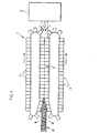
- Figure 1 shows a pipe molding apparatus generally indicated at 1.
- molten plastic is fed from an extruder 2 to a mold tunnel downstream of the extruder.
- Pipe indicated at P emerges from the downstream end of the mold tunnel.
- the mold tunnel is formed by an upper track of mold block sections 3 and a lower track of mold block sections 4.
- the mold block sections meet with one another to define the mold tunnel generally indicated at 5.
- Figure 2 shows a pair of side by side mold block sections 4 from the lower track of mold block sections.
- these mold block sections have an interior face generally indicated at 7 which defines the external shape of the pipe P.
- the interior face of the mold block sections has alternating lands and grooves to produce a ribbed shaping of the pipe.
- Mold block sections 4 are particularly designed for vacuum forming of the pipe in that they are provided with small vacuum slits 9 at each trough in the mold block face. For vacuum forming of the pipe, suction is drawn through these vacuum slits which pulls the molten plastic onto the faces of the mold block sections. These vacuum slits may be intermittent or they may be continuous around the semicircular face of each mold block section.
- Figure 2 shows two slits in each trough of each mold block section, however there may only be one slit or more than the two slits shown for each trough.
- Mold block sections 3 in the upper track of mold block sections have an identical construction.
- Figure 3 shows the vacuum forming of the pipe as it occurs in an upstream region of mold tunnel 5.
- the mold block sections 3 and 4 both of which are mounted to mold block carriers 2, are closed tightly with one another in the mold tunnel.
- a source of vacuum 11 which as shown in Figure 3 is located externally of the mold block section is in direct communication with the small slits 9 in the upper mold block section at discrete locations 16, 17 and 18 through passages 13, 14 and 15 respectively. These passages, as shown, go directly through the wall of the upper mold block section.
- Figure 3 shows that when vacuum is applied through both the upper and the lower vacuum source, the plastic is pulled onto the interior surfaces of the two mated mold block sections to shape the pipe P.
- Figure 3a while using the same mold block sections 3 and 4 shows that the pipe can also be blow molded from air pressure applied internally of the pipe as shown by the arrows in Figure 3a. This air pressure pushes the molten plastic outwardly onto the mold block faces.
- the pipe is cooled using openings in the mold block faces and in this case by using the vacuum slits 9 through the mold block sections.
- a cooling gas is introduced from one of the mold block sections into a gap between the mold tunnel and the pipe. Eventually, this cooling gas is drawn out of the mold tunnel through an outlet remote from the location where the gas is introduced to the mold tunnel.
- cooling gas is introduced to the upper mold block section 3.
- the vacuum while being continued in the upstream region of the mold tunnel is replaced by a flow of cooling gas into the mold tunnel in the more downstream region of the tunnel after the pipe has been shaped and sufficiently set to hold its shape.
- Passage 11 which now becomes a pathway for the cooling gas.
- This cooling gas which may be in a number of different forms including outside ambient air or air which is passed through a cooling device, is forced along the passages 13, 14 and 15 and in this case through the vacuum slits 9 in the upper mold block section. These slits now become inlets into the mold tunnel for directing the cooling gas onto the exterior surface of the pipe P.
- Figure 5 shows that the pipe, with some initial cooling, shrinks away from the interior surface of the mold sections creating a gap G between the outside surface of the pipe and the interior face of mold tunnel. This allows the cooling gas to be forced circumferentially around the pipe as indicated by the arrows in gap G to the vacuum slits in the lower mold block section where the gas is then drawn out of the mold tunnel. Therefore, the slits in the lower mold block section which continue to be subjected to vacuum, now become gas outlets from the mold tunnel.
- the cooling gas has two benefits. Firstly, it provides faster cooling and setting up of the pipe. Secondly, it reduces the temperature of the mold blocks which results in greater ability of the mold blocks to absorb heat from the pipe which again allows the pipe to cool and set faster than normal.
- the vacuum slits for both the introduction and the discharge of the cooling gas, preferably cooling air
- the vacuum slits whether they be continuous or intermittent form paths for the cooling air completely through the main body of the mold block sections. Therefore, the cooling air not only runs around and along the interior surfaces of but additionally penetrates into the mold block sections. This substantially enhances cooling the mold block sections. This in turn increases the ability of the mold blocks to cool the pipe particularly after the mold block sections are returned along their endless loops in a much cooler state than normal to the upstream end of the mold tunnel where they are in direct contact with and have the greatest cooling effect on the plastic as it is extruded into the mold tunnel.
- Figure 6 shows a slightly different mold tunnel design comprising a pair of mold block sections 21 and 25 provided with passages 23 and 27 respectively. These passages first provide vacuum paths during formation of the pipe P and later act as cooling gas inlet and outlet passages. They feed into the interior of the mold tunnel along the parting faces of the mold block sections where they meet as indicated at 29 rather than through holes provided directly in the walls of the mold block sections.
- a cooling medium such as a cooling plug or even cooling gas can be introduced interiorly of the pipe simultaneously with the exterior cooling of the pipe.
- a cooling gas is introduced at the interior face of the mold tunnel, e.g. through the slits in the mold blocks, along the parting faces of the mold block sections, or through other inlets provided in the mold block faces. After cooling both the product and the mold blocks the gas is discharged through the downstream end of the mold tunnel which is open for releasing the pipe from the mold tunnel as earlier described with respect to Figure 1 of the drawings.
Landscapes
- Engineering & Computer Science (AREA)
- Mechanical Engineering (AREA)
- Manufacturing & Machinery (AREA)
- Physics & Mathematics (AREA)
- Thermal Sciences (AREA)
- Moulds For Moulding Plastics Or The Like (AREA)
- Blow-Moulding Or Thermoforming Of Plastics Or The Like (AREA)
- Extrusion Moulding Of Plastics Or The Like (AREA)
- Casting Or Compression Moulding Of Plastics Or The Like (AREA)
Claims (4)
- Procédé de fabrication d'un produit plastique dans un moule ayant une région de moule entourée par une paroi de moule, le moule ayant une entrée de gaz vers et une sortie de gaz depuis la région de moule, l'entrée de gaz étant formée dans la paroi de moule et la sortie de gaz étant située loin de l'entrée de gaz, le procédé comprenant le formage du produit dans la région de moule contre la paroi de moule, le retrait du produit de la paroi de moule afin de produire un espace entre le produit et la paroi de moule, puis la circulation d'un gaz de refroidissement dans la région de moule au niveau de l'entrée de gaz, dans l'espace où le gaz passe sur et refroidit à la fois le produit et la paroi de moule, puis son retrait de la région de moule au niveau de la sortie de gaz.
- Procédé de fabrication d'une conduite dans un tunnel de moulage formé d'une première et deuxième section de bloc de moule qui sont adaptées l'une à l'autre afin de former une région de moule entourée par une paroi de moule ayant une surface de moulage intérieure arrondie et une extrémité d'aval ouverte où la conduite quitte la région de moule, ledit procédé comprenant le formage de la conduite contre la surface de moulage, le retrait de la surface de moulage afin de produire un espace entre la surface de moulage et la conduite, puis le passage d'un gaz de refroidissement dans une entrée de gaz allant de la première section de bloc de moule à l'espace dans la région de moule et la circulation du gaz de refroidissement dans l'espace suivant à la fois la conduite et la surface de moule jusqu'à une sortie de gaz de la région de moule qui est éloignée de l'entrée de gaz.
- Procédé selon la revendication 2 dans lequel la sortie de gaz est située dans la deuxième section de bloc de moule et dans lequel ledit procédé comprend la circulation du gaz de manière circulaire dans l'espace autour de la région de moule suivant à la fois la conduite et la surface de moulage de l'entrée de gaz dans la première section de bloc de moule jusqu'à la sortie de gaz dans la deuxième section de bloc de moule.
- Procédé selon la revendication 2 comprenant la circulation du gaz de refroidissement dans l'espace de la région de moule suivant à la fois la conduite et la surface de moulage jusqu'à l'extrémité d'aval ouverte de la région de moule où le gaz de refroidissement sort de la région de moule.
Applications Claiming Priority (3)
| Application Number | Priority Date | Filing Date | Title |
|---|---|---|---|
| US81560397A | 1997-03-12 | 1997-03-12 | |
| US815603 | 1997-03-12 | ||
| PCT/CA1998/000189 WO1998040198A1 (fr) | 1997-03-12 | 1998-03-09 | Procede et dispositif de refroidissement de produit dans un moule |
Publications (2)
| Publication Number | Publication Date |
|---|---|
| EP1007323A1 EP1007323A1 (fr) | 2000-06-14 |
| EP1007323B1 true EP1007323B1 (fr) | 2004-10-27 |
Family
ID=25218280
Family Applications (1)
| Application Number | Title | Priority Date | Filing Date |
|---|---|---|---|
| EP19980907778 Expired - Lifetime EP1007323B1 (fr) | 1997-03-12 | 1998-03-09 | Procede et dispositif de refroidissement de produit dans un moule |
Country Status (10)
| Country | Link |
|---|---|
| US (1) | US6054089A (fr) |
| EP (1) | EP1007323B1 (fr) |
| JP (1) | JP3686089B2 (fr) |
| CN (1) | CN1075974C (fr) |
| AT (1) | ATE280669T1 (fr) |
| CA (1) | CA2280092C (fr) |
| DE (1) | DE69827273T2 (fr) |
| ES (1) | ES2230675T3 (fr) |
| NO (1) | NO317195B1 (fr) |
| WO (1) | WO1998040198A1 (fr) |
Families Citing this family (11)
| Publication number | Priority date | Publication date | Assignee | Title |
|---|---|---|---|---|
| US6213755B1 (en) * | 1997-12-02 | 2001-04-10 | Kabushiki Kaisha Katsuron | Apparatus for manufacturing a molding continuously |
| US6089851A (en) * | 1998-03-26 | 2000-07-18 | Lupke; Manfred A. A. | Mold block with air flow control |
| US20040047932A1 (en) * | 2002-09-09 | 2004-03-11 | Lupke Manfred A. A. | Pipe mold apparatus with contact and air cooling of plastic in a mold tunnel |
| CA2412066A1 (fr) * | 2002-11-18 | 2004-05-18 | Manfred A. A. Lupke | Appareil de moulage de tuyaux a turbulence d'air dans le tunnel de moulage |
| DE102005008470A1 (de) | 2005-02-24 | 2006-09-07 | Fränkische Rohrwerke Gebr. Kirchner Gmbh & Co. Kg | Verfahren und Vorrichtung zur Herstellung eines Kunststoffstrukturrohres |
| US7611660B2 (en) * | 2006-07-18 | 2009-11-03 | Bosler Design Services, Inc. | Apparatus and method for cooling material during continuous vacuum forming |
| CA2607517C (fr) | 2007-10-22 | 2012-01-31 | Manfred A. A. Lupke | Systeme d'extrusion de tuyauterie avec separation du noyau de refroidissement |
| CN109130043B (zh) * | 2018-09-30 | 2024-02-20 | 广东省智能制造研究所 | 一种流延设备用吸风装置 |
| CN113386305B (zh) * | 2020-03-11 | 2023-03-10 | 华为技术有限公司 | 模具及加工方法 |
| JP7687111B2 (ja) * | 2021-07-26 | 2025-06-03 | トヨタ自動車株式会社 | 管体の製造装置 |
| CN115056458A (zh) * | 2022-06-21 | 2022-09-16 | 楚天科技股份有限公司 | 塑料容器成型模具装置及成型方法、连续式吹灌封一体机 |
Family Cites Families (7)
| Publication number | Priority date | Publication date | Assignee | Title |
|---|---|---|---|---|
| DE2061027C3 (de) * | 1970-12-11 | 1982-03-04 | Wilhelm 8730 Bad Kissingen Hegler | Vorrichtung zum Anbringen einer Querprofilierung an einem Rohr aus thermoplastischem Kunststoff |
| US3981663A (en) * | 1973-09-10 | 1976-09-21 | Lupke Gerd Paul Heinrich | Apparatus for making high speed corrugated plastic tubing |
| US4319872A (en) * | 1976-12-01 | 1982-03-16 | Lupke Gerd Paul Heinrich | Apparatus for producing thermoplastic tubing |
| CA1083766A (fr) * | 1977-02-07 | 1980-08-19 | Gerd P.H. Lupke | Appareil servant a la fabrication de tubes thermoplastiques |
| DE3120480A1 (de) * | 1981-05-22 | 1982-12-09 | Hegler, Wilhelm, 8730 Bad Kissingen | Vorrichtung zur herstellung von kunststoffrohren mit querrillen |
| US5525289A (en) * | 1995-01-30 | 1996-06-11 | Lupke; Manfred A. A. | Method and apparatus for cooling hollow molded product |
| FR2733934B1 (fr) * | 1995-05-11 | 1997-06-20 | Corelco | Dispositif de refroidissement pour installation de fabrication en continu de corps tubulaires en matiere synthetique |
-
1998
- 1998-03-09 DE DE69827273T patent/DE69827273T2/de not_active Expired - Lifetime
- 1998-03-09 CN CN98803223A patent/CN1075974C/zh not_active Expired - Lifetime
- 1998-03-09 AT AT98907778T patent/ATE280669T1/de active
- 1998-03-09 EP EP19980907778 patent/EP1007323B1/fr not_active Expired - Lifetime
- 1998-03-09 CA CA002280092A patent/CA2280092C/fr not_active Expired - Fee Related
- 1998-03-09 ES ES98907778T patent/ES2230675T3/es not_active Expired - Lifetime
- 1998-03-09 US US09/037,912 patent/US6054089A/en not_active Expired - Lifetime
- 1998-03-09 JP JP53899698A patent/JP3686089B2/ja not_active Expired - Lifetime
- 1998-03-09 WO PCT/CA1998/000189 patent/WO1998040198A1/fr not_active Ceased
-
1999
- 1999-09-08 NO NO19994351A patent/NO317195B1/no not_active IP Right Cessation
Also Published As
| Publication number | Publication date |
|---|---|
| ATE280669T1 (de) | 2004-11-15 |
| WO1998040198A1 (fr) | 1998-09-17 |
| DE69827273T2 (de) | 2006-02-02 |
| CN1250409A (zh) | 2000-04-12 |
| CA2280092A1 (fr) | 1998-09-17 |
| NO994351D0 (no) | 1999-09-08 |
| US6054089A (en) | 2000-04-25 |
| CN1075974C (zh) | 2001-12-12 |
| CA2280092C (fr) | 2005-08-23 |
| JP3686089B2 (ja) | 2005-08-24 |
| EP1007323A1 (fr) | 2000-06-14 |
| NO317195B1 (no) | 2004-09-13 |
| JP2001508719A (ja) | 2001-07-03 |
| DE69827273D1 (de) | 2004-12-02 |
| ES2230675T3 (es) | 2005-05-01 |
| NO994351L (no) | 1999-09-08 |
Similar Documents
| Publication | Publication Date | Title |
|---|---|---|
| US4865797A (en) | Method and an apparatus for the extrusion of plastic pipes | |
| US6054089A (en) | Method and apparatus of cooling product within a mold | |
| US5945048A (en) | Process and device for extruding polymer melts to form hollow chamber sections | |
| US4192638A (en) | Molding device having heat transfer chambers insulated from each other for molding expandable thermoplastic resin particles | |
| CA2285131C (fr) | Methode de fabrication en continu de canalisation murale jumelee a manchon, et appareil de fabrication | |
| CN100526048C (zh) | 连续制造带管接头的复壁管的方法、复壁管和实施该方法和制造该复壁管的装置 | |
| JP2002531297A (ja) | 螺旋溝を有する射出成形冷却コア | |
| EP0483153B1 (fr) | Procede de formage de tubes par l'application d'aspiration et de pression pneumatique a la surface du mandrin de refroidissement | |
| US5525289A (en) | Method and apparatus for cooling hollow molded product | |
| JPS60229728A (ja) | 押出製品冷却装置 | |
| EP0363716A2 (fr) | Assemblage formant une filière d'extrusion | |
| KR930004048B1 (ko) | 열가소성 수지의 파이프 제조장치 | |
| JP3764048B2 (ja) | 空気流れ制御を有する鋳型ブロック | |
| CA2493235A1 (fr) | Noyau d'un moule pour injection | |
| US7104777B2 (en) | Pipe mold with compensation for pipe shrinkage | |
| JPH10202763A (ja) | 内部に媒体管を備えたカバー・波形管の製造のための方法及び装置 | |
| US3409941A (en) | Apparatus for producing plastic articles | |
| US20040047932A1 (en) | Pipe mold apparatus with contact and air cooling of plastic in a mold tunnel | |
| JPS6036143A (ja) | 継手部を有した二重壁パイプの製造方法 | |
| KR200273525Y1 (ko) | 압출 튜브용 에어 냉각장치 | |
| CA1281523C (fr) | Methode et dispositif d'extrusion de canalisations en matiere plastique | |
| NL193610C (nl) | Werkwijze voor het extruderen van kunststof pijpen. | |
| KR910003868Y1 (ko) | 가교폴리에틸렌 절연케이블의 접속부 몰드 성형장치 | |
| JPH0315296Y2 (fr) | ||
| KR19990017842A (ko) | 합성수지 상.하수관에 연결용 플렌지를 형성시키는 장치 |
Legal Events
| Date | Code | Title | Description |
|---|---|---|---|
| PUAI | Public reference made under article 153(3) epc to a published international application that has entered the european phase |
Free format text: ORIGINAL CODE: 0009012 |
|
| 17P | Request for examination filed |
Effective date: 19990811 |
|
| AK | Designated contracting states |
Kind code of ref document: A1 Designated state(s): AT DE ES FR GB IT NL |
|
| 17Q | First examination report despatched |
Effective date: 20020124 |
|
| GRAP | Despatch of communication of intention to grant a patent |
Free format text: ORIGINAL CODE: EPIDOSNIGR1 |
|
| GRAS | Grant fee paid |
Free format text: ORIGINAL CODE: EPIDOSNIGR3 |
|
| GRAA | (expected) grant |
Free format text: ORIGINAL CODE: 0009210 |
|
| AK | Designated contracting states |
Kind code of ref document: B1 Designated state(s): AT DE ES FR GB IT NL |
|
| REG | Reference to a national code |
Ref country code: GB Ref legal event code: FG4D |
|
| REF | Corresponds to: |
Ref document number: 69827273 Country of ref document: DE Date of ref document: 20041202 Kind code of ref document: P |
|
| REG | Reference to a national code |
Ref country code: ES Ref legal event code: FG2A Ref document number: 2230675 Country of ref document: ES Kind code of ref document: T3 |
|
| PLBE | No opposition filed within time limit |
Free format text: ORIGINAL CODE: 0009261 |
|
| STAA | Information on the status of an ep patent application or granted ep patent |
Free format text: STATUS: NO OPPOSITION FILED WITHIN TIME LIMIT |
|
| ET | Fr: translation filed | ||
| 26N | No opposition filed |
Effective date: 20050728 |
|
| REG | Reference to a national code |
Ref country code: DE Ref legal event code: R082 Ref document number: 69827273 Country of ref document: DE Representative=s name: WUESTHOFF & WUESTHOFF, PATENTANWAELTE PARTG MB, DE Ref country code: DE Ref legal event code: R082 Ref document number: 69827273 Country of ref document: DE Representative=s name: WUESTHOFF & WUESTHOFF PATENT- UND RECHTSANWAEL, DE |
|
| PGFP | Annual fee paid to national office [announced via postgrant information from national office to epo] |
Ref country code: NL Payment date: 20140326 Year of fee payment: 17 |
|
| PGFP | Annual fee paid to national office [announced via postgrant information from national office to epo] |
Ref country code: IT Payment date: 20140324 Year of fee payment: 17 Ref country code: AT Payment date: 20140219 Year of fee payment: 17 Ref country code: FR Payment date: 20140317 Year of fee payment: 17 |
|
| PGFP | Annual fee paid to national office [announced via postgrant information from national office to epo] |
Ref country code: GB Payment date: 20140327 Year of fee payment: 17 |
|
| PGFP | Annual fee paid to national office [announced via postgrant information from national office to epo] |
Ref country code: DE Payment date: 20140327 Year of fee payment: 17 |
|
| REG | Reference to a national code |
Ref country code: DE Ref legal event code: R119 Ref document number: 69827273 Country of ref document: DE |
|
| REG | Reference to a national code |
Ref country code: AT Ref legal event code: MM01 Ref document number: 280669 Country of ref document: AT Kind code of ref document: T Effective date: 20150309 |
|
| GBPC | Gb: european patent ceased through non-payment of renewal fee |
Effective date: 20150309 |
|
| REG | Reference to a national code |
Ref country code: NL Ref legal event code: MM Effective date: 20150401 |
|
| PG25 | Lapsed in a contracting state [announced via postgrant information from national office to epo] |
Ref country code: IT Free format text: LAPSE BECAUSE OF NON-PAYMENT OF DUE FEES Effective date: 20150309 |
|
| REG | Reference to a national code |
Ref country code: FR Ref legal event code: ST Effective date: 20151130 |
|
| PG25 | Lapsed in a contracting state [announced via postgrant information from national office to epo] |
Ref country code: DE Free format text: LAPSE BECAUSE OF NON-PAYMENT OF DUE FEES Effective date: 20151001 Ref country code: GB Free format text: LAPSE BECAUSE OF NON-PAYMENT OF DUE FEES Effective date: 20150309 |
|
| PG25 | Lapsed in a contracting state [announced via postgrant information from national office to epo] |
Ref country code: FR Free format text: LAPSE BECAUSE OF NON-PAYMENT OF DUE FEES Effective date: 20150331 Ref country code: AT Free format text: LAPSE BECAUSE OF NON-PAYMENT OF DUE FEES Effective date: 20150309 |
|
| PGFP | Annual fee paid to national office [announced via postgrant information from national office to epo] |
Ref country code: ES Payment date: 20160328 Year of fee payment: 19 |
|
| PG25 | Lapsed in a contracting state [announced via postgrant information from national office to epo] |
Ref country code: NL Free format text: LAPSE BECAUSE OF NON-PAYMENT OF DUE FEES Effective date: 20150401 |
|
| REG | Reference to a national code |
Ref country code: ES Ref legal event code: FD2A Effective date: 20180507 |
|
| PG25 | Lapsed in a contracting state [announced via postgrant information from national office to epo] |
Ref country code: ES Free format text: LAPSE BECAUSE OF NON-PAYMENT OF DUE FEES Effective date: 20170310 |