EP1010657B1 - Fadeneinblasventil - Google Patents
Fadeneinblasventil Download PDFInfo
- Publication number
- EP1010657B1 EP1010657B1 EP99120636A EP99120636A EP1010657B1 EP 1010657 B1 EP1010657 B1 EP 1010657B1 EP 99120636 A EP99120636 A EP 99120636A EP 99120636 A EP99120636 A EP 99120636A EP 1010657 B1 EP1010657 B1 EP 1010657B1
- Authority
- EP
- European Patent Office
- Prior art keywords
- injection valve
- valve according
- body member
- yarn injection
- coupling
- Prior art date
- Legal status (The legal status is an assumption and is not a legal conclusion. Google has not performed a legal analysis and makes no representation as to the accuracy of the status listed.)
- Expired - Lifetime
Links
- 238000002347 injection Methods 0.000 title claims description 34
- 239000007924 injection Substances 0.000 title claims description 34
- 230000008878 coupling Effects 0.000 claims abstract description 39
- 238000010168 coupling process Methods 0.000 claims abstract description 39
- 238000005859 coupling reaction Methods 0.000 claims abstract description 39
- 230000000295 complement effect Effects 0.000 claims description 3
- 230000000717 retained effect Effects 0.000 claims 3
- 238000007789 sealing Methods 0.000 claims 2
- 239000012530 fluid Substances 0.000 claims 1
- 238000007664 blowing Methods 0.000 description 16
- 210000002105 tongue Anatomy 0.000 description 12
- 229920003023 plastic Polymers 0.000 description 6
- 239000004753 textile Substances 0.000 description 5
- 230000000694 effects Effects 0.000 description 2
- 230000001154 acute effect Effects 0.000 description 1
- 238000004140 cleaning Methods 0.000 description 1
- 238000010276 construction Methods 0.000 description 1
- 238000009434 installation Methods 0.000 description 1
- 230000014759 maintenance of location Effects 0.000 description 1
- 210000000056 organ Anatomy 0.000 description 1
- 230000002093 peripheral effect Effects 0.000 description 1
- 229920001084 poly(chloroprene) Polymers 0.000 description 1
Images


Classifications
-
- F—MECHANICAL ENGINEERING; LIGHTING; HEATING; WEAPONS; BLASTING
- F16—ENGINEERING ELEMENTS AND UNITS; GENERAL MEASURES FOR PRODUCING AND MAINTAINING EFFECTIVE FUNCTIONING OF MACHINES OR INSTALLATIONS; THERMAL INSULATION IN GENERAL
- F16K—VALVES; TAPS; COCKS; ACTUATING-FLOATS; DEVICES FOR VENTING OR AERATING
- F16K5/00—Plug valves; Taps or cocks comprising only cut-off apparatus having at least one of the sealing faces shaped as a more or less complete surface of a solid of revolution, the opening and closing movement being predominantly rotary
- F16K5/06—Plug valves; Taps or cocks comprising only cut-off apparatus having at least one of the sealing faces shaped as a more or less complete surface of a solid of revolution, the opening and closing movement being predominantly rotary with plugs having spherical surfaces; Packings therefor
-
- B—PERFORMING OPERATIONS; TRANSPORTING
- B65—CONVEYING; PACKING; STORING; HANDLING THIN OR FILAMENTARY MATERIAL
- B65H—HANDLING THIN OR FILAMENTARY MATERIAL, e.g. SHEETS, WEBS, CABLES
- B65H51/00—Forwarding filamentary material
- B65H51/16—Devices for entraining material by flow of liquids or gases, e.g. air-blast devices
-
- B—PERFORMING OPERATIONS; TRANSPORTING
- B65—CONVEYING; PACKING; STORING; HANDLING THIN OR FILAMENTARY MATERIAL
- B65H—HANDLING THIN OR FILAMENTARY MATERIAL, e.g. SHEETS, WEBS, CABLES
- B65H2701/00—Handled material; Storage means
- B65H2701/30—Handled filamentary material
- B65H2701/31—Textiles threads or artificial strands of filaments
Definitions
- the invention relates to a thread injection valve, in particular for inserting textile threads into thread guide tubes, how to transfer threads from a creel can be provided for a textile machine.
- a thread injection valve known.
- the open end of a thread guide tube an air nozzle is arranged opposite, from which a valve controlled compressed air can be discharged, which then rinses the thread into the thread guide tube.
- the thread injection valve lies in a compressed air line.
- the compressed air line, the thread guide tube and the thread injection valve are mounted outside on a support.
- the air inlet of the thread injection valve is open End of the thread guide tube on the opposite side arranged offset against this in order to bring it sideways of the thread to the open end of the thread guide tube to allow. Due to the asymmetrical arrangement Operation determined for right-handers, for example.
- Gates for bobbins are usually made on site prefabricated parts erected. The installation and setup the gate with all the necessary organs, such as For example, also thread injection valves, should be easy to install Way done. In addition, one should look as possible clear structure. Furthermore applies it should be noted that gates, like almost all in textile factories existing facilities, pollution due to river deposits. This also applies counteract.
- the thread injection valve according to the invention is at least constructed in two parts and into a basic body and a Connector divided. These are via a coupling device connectable with each other.
- the connector is preferably one Compressed air line assigned, and the base body is preferred assigned to a thread guide tube. So that can Connection piece first in the compressed air line be installed before it is also mounted on the separately Base body is coupled. This simplifies the Assembly.
- the two-part design allows Laying the compressed air line along with connectors e.g. inside of hollow profiles or open on one side Profiles, such as U-profiles or the like, for example Carrier elements of the gate serve or provided on this are. In this way, the compressed air line Lay invisibly. This makes the overall structure smoother and there are less accessible areas or areas on which deposits accumulate.
- the coupling device connects a provided in the connector with air supply duct an air duct formed in the base body and additionally the mechanical connection between the Connector and the base body. While the connector the connection of the hoses, for example Compressed air line is used on the base body a blow valve leading air valve provided.
- the two Parts of the thread injection valve, i.e. the basic body and the connector, are on both sides of a wall of the Carrier element arranged.
- a coupling half protrudes when opening through the wall. It does not come here essential to their accuracy and precision, freedom from burrs, Shape retention etc. It can do more or more there is less play without affecting the function.
- the preferably complementary to each other Coupling halves seal regardless of size and Precision of the opening mentioned fluid-tight with each other.
- the coupling halves are considered to be particularly useful to be designed so that the coupling can be released. This makes disassembly easy.
- a detachable Connection can e.g. with a snap connection or several locking tongues are formed, which are part of the coupling halves are. These can be mechanically secured of the base body on the connector or the connector effect on the base body.
- the coupling device can at the same time determine the thread injection valve serve on the carrier if, for example, the carrier between the connector and the base body clamped becomes.
- additional fasteners can be attached the base body and / or the connector is provided his.
- the fasteners can be screws, locking pins, Snap tongues or the like.
- the Coupling halves at least around a limited range of rotation rotatable against each other.
- the axis of rotation is in the Essentially transverse to and parallel to the through channel aligned with the air supply duct. This allows hoses for supplying compressed air around the thread guide tube be led around.
- the compressed air hoses mostly trained a little longer than necessary are meandered in the channel. By the rotatability of the connector can this to the Hose guide can be adjusted.
- the connector preferably has one Through channel from which the air supply duct branches.
- the through channel is preferably with two connections provided that allow several connectors in a row to be placed in a compressed air line.
- the connections can be simple hose connections to which an air hose is pushed on.
- the valve means arranged in the base body is preferably a ball valve with a plastic one, e.g. neoprene, trained ball. This is from that Actuator separate, i.e. not connected to this.
- the actuator has only one when actuated the plunger pushing the ball away from its valve seat on. This causes the actuator to play laterally for the tightness of the valve when closed not matter. Between the actuator and the Valve closure member is preferred in the non-actuated state there is a certain distance. By side Force applied to the control knob or only very slight Pressing the control button will still the valve Not open.
- the actuator can be sealed by gap seals his. This can be done, for example, by a rib-like Projection can be achieved on the control button, which in corresponding Recesses of the base body engages. As a result which makes it possible that when the control element is actuated no air escapes to the operating personnel.
- the pressed actuation button preferably has an edge that engages in a groove in the housing. This is how one becomes Gap seal designed that prevents compressed air flows out towards the operator side.
- control button can be designed so that it snaps into place with the base body is, wherein a locking element, for example a locking tongue, is accessible from the outside to the control button of the To be able to solve the basic body.
- the blowing nozzle is preferably a relatively long channel formed with a constant cross-sectional shape to the To allow a laminar air jet to emerge. This is bundled very well and thus brings about a good one Thread entry also in long thread guide tubes.
- a holder for is preferably on the base body a catch nozzle and a connection for the thread guide tube intended.
- This bracket can, for example, a spring clip be in one piece with the plastic, for example Basic body is formed.
- the spring clip specifies a direction for the catch nozzle and the thread guide tube, which preferably coincides with the direction of the blow nozzle.
- the direction is in a preferred embodiment at an acute angle to the base of the base body arranged.
- the thread guide tube runs at an angle away from the base body into the carrier profile. It this enables the thread guide tubes within To lay support profiles. It follows, in particular if both the thread guide tubes and the compressed air lines are arranged in the carrier profile, a particular smooth simple construction.
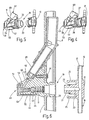
- a carrier element 1 is illustrated in FIG. 1, that provided on a part of the creel can be.
- the carrier element 1 is, for example, a plastic profile, as it is also used as a cable duct for other purposes Can be found.
- the plastic profile can be closed or be open as a U-profile. It can also be a gutter-shaped Have base body 2 and an associated cover wall 3, which is locked to the base body 2 to a to form a closed profile.
- a thread blowing valve 4 is on the carrier profile 1 arranged with one end one of one no further shown bobbin coming thread 6 in an open End 7 of a thread guide tube 8 is inflatable.
- the thread guide tube 8 extends from the thread injection valve 4, which is placed near a spool on a creel is close to a thread-taking device, for example a thread delivery device.
- the thread guide tube 8 stores and guides the thread 6. As illustrated in FIG. 1, The thread guide tube 8 largely runs in the interior of the carrier profile 1. The outside of the same is therefore free of pipes.
- FIG 2 the thread injection valve 4 is separate illustrated. It is also apparent from Figure 3. How can be seen, the thread injection valve 4 in a base body 11 and an associated connector 12 divided, the connection of one in Figure 3 only schematically indicated and shown in Figure 1 compressed air line 14 serves. To connect the same points Connector 12 on opposite sides two tubular extensions 15 each profiled on the outside, 16 on each other through a through-channel 17 are connected.
- the connector 12 is by means of a coupling device 18 connected to the base body 11.
- a coupling device 18 To the Coupling device 18 include a body side Coupling half 19 and a coupling half on the connector side 20. Both coupling halves 19, 20 are in relation to each other Complementarily trained so that they interlock fit.
- Connector 12 To form the coupling half 20, this has Connector 12 has a tubular extension 21 on the its free end is tapered. In connection to its conical area is an annular groove on the neck 21 provided with an O-ring 22 seated therein, which as Seal serves.
- the tubular extension 21 also delimits an air supply duct 23 which is from the through duct 17 branches and opens at the free end of the approach 21.
- the base body 11 and around the coupling halves 19, 20 in to keep fluid-tight coupled condition on the Connector 12 two approximately parallel to the approach spring tongues 24, 25 extending toward base body 11 provided, each with a free end Are provided.
- the spring tongues 24, 25 are in one piece formed with the connector 12, the example. consists of plastic. You are away from approach 21 and deflectable towards it.
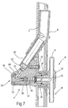
- the coupling half 19 belonging to the base body 11 also has a tubular extension 28 which the Closure or cover wall 3 at a mounting opening 29 be upheld.
- the tubular extension 28 is at least provided on one side with a groove-like recess 31, which engages behind the cover wall 3 at its opening 29. Otherwise, the base body 11 lies with a flat surface 32 on the cover wall 3. If necessary, he can by a fastening element, such as a screw 34, be secured to the cover wall 3.
- the tubular extension 28 of the coupling half 19th extends through the cover wall 3 and has an opening that Complementary to the outer shape of the extension 21 is.
- approach 28 fits so far on the extension 21 that it sits firmly in it.
- locking pockets 37, 38 provided, in which the locking lugs of the spring tongues 24, 25th engage when the coupling halves 19, 20 together are engaged. This forms the locking pockets 37, 38 and the locking tongues 24, 25 a mechanical connection device for the base body 11 and the connector 12.
- An air duct 39 is formed in the base body 11, from the coupling half 19 to a ball valve 41 and from this leads to a blow nozzle 42.
- the ball valve 41 is formed by a plastic ball 43 which serves as a valve closure member and one preferably conical ring surface 44 is assigned as a valve seat.
- the Ball 43 is against the ring surface by a coil spring 45 44 pressed, the coil spring 45 on a securing element 46 seated in the air duct 39 supported.
- the securing element 46 is supported here projections arranged at an angle to the radial direction on the smooth wall of the air duct 39 and is thereby Held place.
- the Air duct 39 into a stepped bore 47 in the one Shaft 48 of an actuator sits. This is through an operating button 49 is formed.
- the control button 49 has a peripheral edge 51 which fits into a corresponding approximately matching recess 52 of the base body engages. Between the collar or edge 51 and the recess 52 is both externally and internally a relative narrow gap formed.
- the control button end of the the channel 39 forming stepped bore is from a in Diameter with the air duct 39 approximately matching End 53 of the extending from the control button 49 away Shaft 48 closed so that at most a relative narrow gap between the bore and the end 53 remains.
- the shaft 48 then extends with somewhat less Diameter and / or one for the purpose of air passage provided longitudinal recess 54 to the ball 43.
- the shaft 48 is dimensioned so short that between the ball 43 and the front end of the shaft 48 Distance remains when the control button 49 is not actuated becomes.
- the locking tongue 55 has a T-shaped Head up behind the appropriate leadership and Stop ribs 56, 57 of the base body 11 engage. This are parallel to the securing tongue 55 on both sides the same is formed on the base body 11.
- the safety tongue 55 can from between the two guide ribs 56, 57 defined path can be lifted out to the control button 49 to be able to remove from the base body 11. in the however, it is in a relaxed state on the base body 11 on and holds the control button 49 captive and in the longitudinal direction slidably on the base body 11.
- the blowing nozzle 49 branching off from the air duct 39 becomes formed by a relatively narrow e.g. cylindrical channel, the center axis of which is pointed with the flat surface 32 Includes angle. This blows out of the blowing nozzle 42 escaping air obliquely towards the cover wall 3.
- the Blower nozzle lies at some distance from the control button 49 one end of a concave surface 60, which in a narrow edge 61 runs out. In the edge 61 is a funnel-like Cutout or notch formed the bottom of which is the mouth of the blowing nozzle 42. This serves generating a directional air jet for entry of thread 6 in the thread guide tube 8.
- the notch also takes a part of the curved surface 60, so that the Blow nozzle 42 in the immediate vicinity of surface 60 empties. This allows threads to be very easily and freely be brought up to the blowing nozzle 42.
- a blowing nozzle 62 is located opposite the blowing nozzle 42 arranged, which narrows a conical funnel-like Entry area 63 and an adjoining area cylindrical region 64.
- the capture nozzle 62 sits in a guide tube 65, the central axis of which Axis of the blowing nozzle 42 coincides.
- the area 60 leaves however, part of the entry area 63 of the catch nozzle 62 free, so that a thread in the between the catch nozzle 62nd and the blowing nozzle 42 formed suction gap can be. This can be done from the right as well as from happen to the left so that the blow valve 4 does not open operation by right or left-handers is restricted is.
- the guide tube 65 is inserted with its from the blow nozzle 42 remote end in the thread guide tube 8, which in the Carrier profile 1 is arranged and by a corresponding Opening 66 protrudes outwards.
- a spring clip 67 which emerges from FIG. 2 and is part of the base body 11 is.
- the spring clip 67 has two in use the guide tube 65 encompassing legs 68, 69, the the guide tube 65 between them as required however keep detachable.
- the thread blowing valve 4 described so far works as follows:
- the thread injection valve When installed, the thread injection valve is in Figures 1 and 3 illustrates.
- the spring 45 presses the ball 43 to the annular surface 44 so that the air duct 39 is closed.
- the control element 49 lies with his Do not shaft 48 on ball 43.
- the connector 12 is coupled to the base body 11, whereby the coupling halves 19, 20 are in engagement with each other.
- the Locking tongues 24, 25 hold the connector 12 on the Base body 11. Compressed air lies over the compressed air line 14 on the passage duct 17 and thus on the air supply duct 23 on. However, the ball 43 blocks the compressed air access to the blow nozzle 42.
- the air duct remains 49 relatively well sealed from the outside.
- the control button 49 forms a triple gap seal with two buffer spaces.
- the first buffer space is below the control button 49 defined, while the second buffer space between the Bund or the rib 51 and the corresponding recess 52 is limited.
- the triple arrangement of the Gap seals can also tolerate slightly wider gaps be without causing too much air loss comes.
- a thread injection valve 9 is constructed in two parts, it in a base body 11 and a connector 12th is divided. This allows a simple way To arrange compressed air line 14 behind a cover wall 3, which is penetrated by the blow valve. To the assembly by connecting the base body 11 to the connector 12 to enable a coupling device between the two intended.
Landscapes
- General Engineering & Computer Science (AREA)
- Engineering & Computer Science (AREA)
- Mechanical Engineering (AREA)
- Spinning Or Twisting Of Yarns (AREA)
- Self-Closing Valves And Venting Or Aerating Valves (AREA)
- Yarns And Mechanical Finishing Of Yarns Or Ropes (AREA)
- Endoscopes (AREA)
- Mechanically-Actuated Valves (AREA)
- Coating Apparatus (AREA)
- Check Valves (AREA)
- Hydraulic Clutches, Magnetic Clutches, Fluid Clutches, And Fluid Joints (AREA)
- Glass Compositions (AREA)
- Superconductors And Manufacturing Methods Therefor (AREA)
- Resistance Heating (AREA)
- Jet Pumps And Other Pumps (AREA)
- Treatment Of Fiber Materials (AREA)
- Nozzles (AREA)
- Reciprocating Pumps (AREA)
Applications Claiming Priority (2)
| Application Number | Priority Date | Filing Date | Title |
|---|---|---|---|
| DE19851957A DE19851957C1 (de) | 1998-11-11 | 1998-11-11 | Fadeneinblasventil |
| DE19851957 | 1998-11-11 |
Publications (3)
| Publication Number | Publication Date |
|---|---|
| EP1010657A2 EP1010657A2 (de) | 2000-06-21 |
| EP1010657A3 EP1010657A3 (de) | 2001-06-20 |
| EP1010657B1 true EP1010657B1 (de) | 2003-08-13 |
Family
ID=7887398
Family Applications (1)
| Application Number | Title | Priority Date | Filing Date |
|---|---|---|---|
| EP99120636A Expired - Lifetime EP1010657B1 (de) | 1998-11-11 | 1999-10-18 | Fadeneinblasventil |
Country Status (10)
| Country | Link |
|---|---|
| US (1) | US6367675B1 (pt) |
| EP (1) | EP1010657B1 (pt) |
| KR (1) | KR100338172B1 (pt) |
| CN (1) | CN1100899C (pt) |
| AT (1) | ATE247069T1 (pt) |
| DE (2) | DE19851957C1 (pt) |
| ES (1) | ES2200452T3 (pt) |
| PT (1) | PT1010657E (pt) |
| TR (1) | TR199902781A3 (pt) |
| TW (1) | TW473451B (pt) |
Families Citing this family (6)
| Publication number | Priority date | Publication date | Assignee | Title |
|---|---|---|---|---|
| US6467754B2 (en) * | 2000-02-24 | 2002-10-22 | Delphi Technologies, Inc. | Adaptable gas and moisture shield for a gas management valve |
| US7017244B2 (en) * | 2002-06-03 | 2006-03-28 | Hunter Douglas Inc. | Beam winding apparatus |
| US7695486B2 (en) * | 2002-10-02 | 2010-04-13 | Linda Dixon | Intradermal color introducing needle device, and apparatus and method involving the same |
| CN101245506B (zh) * | 2008-03-27 | 2010-06-23 | 江苏凯宫机械股份有限公司 | 精梳机的圈条器 |
| CN101684587A (zh) * | 2008-09-25 | 2010-03-31 | 陈仁惠 | 气动式送纱装置 |
| US11708648B2 (en) * | 2020-05-05 | 2023-07-25 | Columbia Insurance Company | Aspirator for manipulating filaments |
Family Cites Families (10)
| Publication number | Priority date | Publication date | Assignee | Title |
|---|---|---|---|---|
| US1874541A (en) * | 1928-05-14 | 1932-08-30 | Lubrication Corp | Lubricating device |
| FR1045449A (fr) * | 1951-11-26 | 1953-11-26 | Ryo Catteau Sa Ets | Dispositif pneumatique d'enfilage axial des fils dans les broches et ailettes |
| DE1660671A1 (de) * | 1965-11-10 | 1970-12-17 | Glanzstoff Ag | Vorrichtung zum Erleichtern des Spulenwechsels |
| US3633808A (en) * | 1969-06-06 | 1972-01-11 | Elitex Z Textilniho Shojirenst | Nozzle for jet looms |
| BE759801A (fr) * | 1969-12-04 | 1971-05-17 | Snia Viscosa | Perfectionnements apportes aux dispositifs pour ramasser, aspirer et eliminer des filaments et fils textiles, ainsi que les dispositifs perfectionnes obtenus |
| GB2019450B (en) * | 1978-04-25 | 1982-06-03 | Hamel Gmbh Zwirnmaschinen | Up-twisting machines |
| US4776369A (en) * | 1987-02-24 | 1988-10-11 | Halkey-Roberts Corporation | Check valve having snap-on clamping sleeve |
| US5024393A (en) * | 1990-04-27 | 1991-06-18 | Alandale Industries, Inc. | Yarn threading apparatus for tube-type textile yarn creels |
| JP2842677B2 (ja) * | 1990-08-27 | 1999-01-06 | 三井化学株式会社 | 不織布製造用エアガン |
| US5323982A (en) * | 1993-01-08 | 1994-06-28 | Ligon Lang S | Low profile yarn supply apparatus for a loom having pneumatic yarn threading |
-
1998
- 1998-11-11 DE DE19851957A patent/DE19851957C1/de not_active Expired - Fee Related
-
1999
- 1999-10-18 DE DE59906581T patent/DE59906581D1/de not_active Expired - Lifetime
- 1999-10-18 AT AT99120636T patent/ATE247069T1/de not_active IP Right Cessation
- 1999-10-18 PT PT99120636T patent/PT1010657E/pt unknown
- 1999-10-18 ES ES99120636T patent/ES2200452T3/es not_active Expired - Lifetime
- 1999-10-18 EP EP99120636A patent/EP1010657B1/de not_active Expired - Lifetime
- 1999-11-05 TW TW088119273A patent/TW473451B/zh not_active IP Right Cessation
- 1999-11-10 KR KR1019990049681A patent/KR100338172B1/ko not_active Expired - Fee Related
- 1999-11-10 US US09/438,097 patent/US6367675B1/en not_active Expired - Fee Related
- 1999-11-11 CN CN99123557A patent/CN1100899C/zh not_active Expired - Fee Related
- 1999-11-11 TR TR1999/02781A patent/TR199902781A3/tr unknown
Also Published As
| Publication number | Publication date |
|---|---|
| KR20000035378A (ko) | 2000-06-26 |
| TR199902781A2 (xx) | 2000-06-21 |
| ES2200452T3 (es) | 2004-03-01 |
| CN1253190A (zh) | 2000-05-17 |
| ATE247069T1 (de) | 2003-08-15 |
| TR199902781A3 (tr) | 2000-06-21 |
| US6367675B1 (en) | 2002-04-09 |
| KR100338172B1 (ko) | 2002-05-24 |
| CN1100899C (zh) | 2003-02-05 |
| DE19851957C1 (de) | 2000-04-20 |
| DE59906581D1 (de) | 2003-09-18 |
| PT1010657E (pt) | 2003-11-28 |
| TW473451B (en) | 2002-01-21 |
| EP1010657A2 (de) | 2000-06-21 |
| EP1010657A3 (de) | 2001-06-20 |
Similar Documents
| Publication | Publication Date | Title |
|---|---|---|
| DE69818177T2 (de) | Rohrverbindung für einen unter Druck stehenden Apparat | |
| DE3140928C2 (de) | Vorrichtung für das nachträgliche Einziehen von Fernmeldekabeln | |
| DE4425863A1 (de) | Saug- und Blasvorrichtung | |
| DE4036083C2 (de) | Dosiereinrichtung | |
| DE4220006B4 (de) | Verbessertes System zum Steuern des Stromes von Luft und Wasser zu einer Mehrzahl von dentalen Handstücken | |
| EP1010657B1 (de) | Fadeneinblasventil | |
| CH648608A5 (de) | Verfahren und vorrichtung zum spleissen von zwei fadenenden. | |
| DE19636579A1 (de) | Ansaugvorrichtung für mehrzylindrige Verbrennungsmotoren | |
| DE3500500A1 (de) | Stellventil | |
| DE19829769C2 (de) | Mischvorrichtung zum Einbringen eines Fluides in ein strömendes, anderes Fluid | |
| DE9212228U1 (de) | Einsteckkupplung für die Verbindung von zwei Kunststoffrohren | |
| DE3924795C2 (de) | Fluid-Anschlußeinrichtung | |
| DE3604643C2 (pt) | ||
| EP2072695B2 (de) | Unterputzspülkasten mit einem Anschlussstück zum Anschliessen einer Wasserversorgungsleitung und Verfahren zum Anschliessen eines Unterputzspülkastens an eine Wasserversorgungsleitung | |
| EP0607166B1 (de) | Vorrichtung zum ansaugen von zusatzstoffen in eine fluidströmung | |
| DE10143296A1 (de) | Kabeldurchführungssystem für konfektionierte Leitungen | |
| DE19505647C2 (de) | Anordnung zum Versprühen eines Zweistoffgemisches | |
| DE29505161U1 (de) | Verschlußventil für Absauganlagen | |
| EP3572739B9 (de) | Durchlass einer klimatechnischen anlage zur be- und/oder zur entlüftung von räumen | |
| EP0361055A1 (de) | Vorrichtung zum Umlenken von Hochdruckschläuchen | |
| EP0568904A1 (de) | Mischeinrichtung für flüssige Medien | |
| DE60208720T2 (de) | Wandhalter für abgabevorrichtung | |
| DE2621810C3 (de) | Schäumpistole zum Erzeugen eines Mehrkomponenten-Schaumes im Niederdruckverfahren | |
| WO1992017270A1 (de) | Vorrichtung zum mischen von fluiden | |
| DE4334314A1 (de) | Selbstklemmender Schlauchanschluß |
Legal Events
| Date | Code | Title | Description |
|---|---|---|---|
| PUAI | Public reference made under article 153(3) epc to a published international application that has entered the european phase |
Free format text: ORIGINAL CODE: 0009012 |
|
| AK | Designated contracting states |
Kind code of ref document: A2 Designated state(s): AT BE CH CY DE DK ES FI FR GB GR IE IT LI LU MC NL PT SE |
|
| AX | Request for extension of the european patent |
Free format text: AL;LT;LV;MK;RO;SI |
|
| PUAL | Search report despatched |
Free format text: ORIGINAL CODE: 0009013 |
|
| AK | Designated contracting states |
Kind code of ref document: A3 Designated state(s): AT BE CH CY DE DK ES FI FR GB GR IE IT LI LU MC NL PT SE |
|
| AX | Request for extension of the european patent |
Free format text: AL;LT;LV;MK;RO;SI |
|
| 17P | Request for examination filed |
Effective date: 20010721 |
|
| AKX | Designation fees paid |
Free format text: AT BE CH CY DE DK ES FI FR GB GR IE IT LI LU MC NL PT SE |
|
| GRAH | Despatch of communication of intention to grant a patent |
Free format text: ORIGINAL CODE: EPIDOS IGRA |
|
| GRAH | Despatch of communication of intention to grant a patent |
Free format text: ORIGINAL CODE: EPIDOS IGRA |
|
| GRAA | (expected) grant |
Free format text: ORIGINAL CODE: 0009210 |
|
| AK | Designated contracting states |
Designated state(s): AT BE CH CY DE DK ES FI FR GB GR IE IT LI LU MC NL PT SE |
|
| PG25 | Lapsed in a contracting state [announced via postgrant information from national office to epo] |
Ref country code: NL Free format text: LAPSE BECAUSE OF FAILURE TO SUBMIT A TRANSLATION OF THE DESCRIPTION OR TO PAY THE FEE WITHIN THE PRESCRIBED TIME-LIMIT Effective date: 20030813 Ref country code: IE Free format text: LAPSE BECAUSE OF FAILURE TO SUBMIT A TRANSLATION OF THE DESCRIPTION OR TO PAY THE FEE WITHIN THE PRESCRIBED TIME-LIMIT Effective date: 20030813 Ref country code: FI Free format text: LAPSE BECAUSE OF FAILURE TO SUBMIT A TRANSLATION OF THE DESCRIPTION OR TO PAY THE FEE WITHIN THE PRESCRIBED TIME-LIMIT Effective date: 20030813 |
|
| REG | Reference to a national code |
Ref country code: GB Ref legal event code: FG4D Free format text: NOT ENGLISH |
|
| REG | Reference to a national code |
Ref country code: CH Ref legal event code: EP |
|
| REG | Reference to a national code |
Ref country code: IE Ref legal event code: FG4D Free format text: GERMAN |
|
| REF | Corresponds to: |
Ref document number: 59906581 Country of ref document: DE Date of ref document: 20030918 Kind code of ref document: P |
|
| REG | Reference to a national code |
Ref country code: GR Ref legal event code: EP Ref document number: 20030403813 Country of ref document: GR |
|
| PG25 | Lapsed in a contracting state [announced via postgrant information from national office to epo] |
Ref country code: LU Free format text: LAPSE BECAUSE OF NON-PAYMENT OF DUE FEES Effective date: 20031018 Ref country code: CY Free format text: LAPSE BECAUSE OF FAILURE TO SUBMIT A TRANSLATION OF THE DESCRIPTION OR TO PAY THE FEE WITHIN THE PRESCRIBED TIME-LIMIT Effective date: 20031018 Ref country code: AT Free format text: LAPSE BECAUSE OF NON-PAYMENT OF DUE FEES Effective date: 20031018 |
|
| PG25 | Lapsed in a contracting state [announced via postgrant information from national office to epo] |
Ref country code: MC Free format text: LAPSE BECAUSE OF NON-PAYMENT OF DUE FEES Effective date: 20031031 Ref country code: LI Free format text: LAPSE BECAUSE OF NON-PAYMENT OF DUE FEES Effective date: 20031031 Ref country code: CH Free format text: LAPSE BECAUSE OF NON-PAYMENT OF DUE FEES Effective date: 20031031 Ref country code: BE Free format text: LAPSE BECAUSE OF NON-PAYMENT OF DUE FEES Effective date: 20031031 |
|
| PG25 | Lapsed in a contracting state [announced via postgrant information from national office to epo] |
Ref country code: SE Free format text: LAPSE BECAUSE OF FAILURE TO SUBMIT A TRANSLATION OF THE DESCRIPTION OR TO PAY THE FEE WITHIN THE PRESCRIBED TIME-LIMIT Effective date: 20031113 Ref country code: DK Free format text: LAPSE BECAUSE OF FAILURE TO SUBMIT A TRANSLATION OF THE DESCRIPTION OR TO PAY THE FEE WITHIN THE PRESCRIBED TIME-LIMIT Effective date: 20031113 |
|
| GBT | Gb: translation of ep patent filed (gb section 77(6)(a)/1977) |
Effective date: 20031217 |
|
| NLV1 | Nl: lapsed or annulled due to failure to fulfill the requirements of art. 29p and 29m of the patents act | ||
| REG | Reference to a national code |
Ref country code: ES Ref legal event code: FG2A Ref document number: 2200452 Country of ref document: ES Kind code of ref document: T3 |
|
| REG | Reference to a national code |
Ref country code: IE Ref legal event code: FD4D |
|
| BERE | Be: lapsed |
Owner name: *MEMMINGER-IRO G.M.B.H. Effective date: 20031031 |
|
| ET | Fr: translation filed | ||
| REG | Reference to a national code |
Ref country code: CH Ref legal event code: PL |
|
| PLBE | No opposition filed within time limit |
Free format text: ORIGINAL CODE: 0009261 |
|
| STAA | Information on the status of an ep patent application or granted ep patent |
Free format text: STATUS: NO OPPOSITION FILED WITHIN TIME LIMIT |
|
| 26N | No opposition filed |
Effective date: 20040514 |
|
| PGFP | Annual fee paid to national office [announced via postgrant information from national office to epo] |
Ref country code: GB Payment date: 20051004 Year of fee payment: 7 |
|
| PGFP | Annual fee paid to national office [announced via postgrant information from national office to epo] |
Ref country code: GR Payment date: 20061030 Year of fee payment: 8 |
|
| GBPC | Gb: european patent ceased through non-payment of renewal fee |
Effective date: 20061018 |
|
| PG25 | Lapsed in a contracting state [announced via postgrant information from national office to epo] |
Ref country code: GB Free format text: LAPSE BECAUSE OF NON-PAYMENT OF DUE FEES Effective date: 20061018 |
|
| PGFP | Annual fee paid to national office [announced via postgrant information from national office to epo] |
Ref country code: ES Payment date: 20071026 Year of fee payment: 9 |
|
| PGFP | Annual fee paid to national office [announced via postgrant information from national office to epo] |
Ref country code: FR Payment date: 20071019 Year of fee payment: 9 |
|
| PGFP | Annual fee paid to national office [announced via postgrant information from national office to epo] |
Ref country code: PT Payment date: 20071016 Year of fee payment: 9 |
|
| REG | Reference to a national code |
Ref country code: PT Ref legal event code: MM4A Free format text: LAPSE DUE TO NON-PAYMENT OF FEES Effective date: 20090420 |
|
| PG25 | Lapsed in a contracting state [announced via postgrant information from national office to epo] |
Ref country code: GR Free format text: LAPSE BECAUSE OF NON-PAYMENT OF DUE FEES Effective date: 20080505 |
|
| REG | Reference to a national code |
Ref country code: FR Ref legal event code: ST Effective date: 20090630 |
|
| PG25 | Lapsed in a contracting state [announced via postgrant information from national office to epo] |
Ref country code: PT Free format text: LAPSE BECAUSE OF NON-PAYMENT OF DUE FEES Effective date: 20090420 |
|
| PG25 | Lapsed in a contracting state [announced via postgrant information from national office to epo] |
Ref country code: FR Free format text: LAPSE BECAUSE OF NON-PAYMENT OF DUE FEES Effective date: 20081031 |
|
| REG | Reference to a national code |
Ref country code: ES Ref legal event code: FD2A Effective date: 20081020 |
|
| PG25 | Lapsed in a contracting state [announced via postgrant information from national office to epo] |
Ref country code: ES Free format text: LAPSE BECAUSE OF NON-PAYMENT OF DUE FEES Effective date: 20081020 |
|
| PGFP | Annual fee paid to national office [announced via postgrant information from national office to epo] |
Ref country code: IT Payment date: 20101028 Year of fee payment: 12 |
|
| PGFP | Annual fee paid to national office [announced via postgrant information from national office to epo] |
Ref country code: DE Payment date: 20111216 Year of fee payment: 13 |
|
| PG25 | Lapsed in a contracting state [announced via postgrant information from national office to epo] |
Ref country code: DE Free format text: LAPSE BECAUSE OF NON-PAYMENT OF DUE FEES Effective date: 20130501 |
|
| REG | Reference to a national code |
Ref country code: DE Ref legal event code: R119 Ref document number: 59906581 Country of ref document: DE Effective date: 20130501 |
|
| PG25 | Lapsed in a contracting state [announced via postgrant information from national office to epo] |
Ref country code: IT Free format text: LAPSE BECAUSE OF NON-PAYMENT OF DUE FEES Effective date: 20121018 |