EP1016533B3 - Module d'alimentation en encre - Google Patents
Module d'alimentation en encre Download PDFInfo
- Publication number
- EP1016533B3 EP1016533B3 EP19990929867 EP99929867A EP1016533B3 EP 1016533 B3 EP1016533 B3 EP 1016533B3 EP 19990929867 EP19990929867 EP 19990929867 EP 99929867 A EP99929867 A EP 99929867A EP 1016533 B3 EP1016533 B3 EP 1016533B3
- Authority
- EP
- European Patent Office
- Prior art keywords
- ink
- supply unit
- ink supply
- movable
- valve
- Prior art date
- Legal status (The legal status is an assumption and is not a legal conclusion. Google has not performed a legal analysis and makes no representation as to the accuracy of the status listed.)
- Expired - Lifetime
Links
- 230000001105 regulatory effect Effects 0.000 claims abstract description 3
- 239000012528 membrane Substances 0.000 claims description 57
- 239000003570 air Substances 0.000 claims description 30
- 238000007789 sealing Methods 0.000 claims description 14
- 230000035699 permeability Effects 0.000 claims description 10
- 239000012080 ambient air Substances 0.000 claims description 4
- 238000002347 injection Methods 0.000 claims description 4
- 239000007924 injection Substances 0.000 claims description 4
- 239000000463 material Substances 0.000 claims description 4
- 239000002861 polymer material Substances 0.000 claims description 4
- 230000002940 repellent Effects 0.000 claims description 2
- 239000005871 repellent Substances 0.000 claims description 2
- 238000011144 upstream manufacturing Methods 0.000 claims 5
- 230000002093 peripheral effect Effects 0.000 claims 1
- 239000007779 soft material Substances 0.000 claims 1
- 230000007246 mechanism Effects 0.000 abstract description 30
- 230000001502 supplementing effect Effects 0.000 description 14
- 238000005192 partition Methods 0.000 description 11
- 238000007639 printing Methods 0.000 description 11
- 230000003247 decreasing effect Effects 0.000 description 10
- 239000004743 Polypropylene Substances 0.000 description 8
- -1 polypropylene Polymers 0.000 description 8
- 229920001155 polypropylene Polymers 0.000 description 8
- 230000008859 change Effects 0.000 description 5
- 238000000034 method Methods 0.000 description 5
- 230000008878 coupling Effects 0.000 description 4
- 238000010168 coupling process Methods 0.000 description 4
- 238000005859 coupling reaction Methods 0.000 description 4
- 238000000465 moulding Methods 0.000 description 4
- 229920006254 polymer film Polymers 0.000 description 4
- 230000008569 process Effects 0.000 description 4
- 238000011084 recovery Methods 0.000 description 4
- 238000004891 communication Methods 0.000 description 3
- 230000000694 effects Effects 0.000 description 3
- 238000001746 injection moulding Methods 0.000 description 3
- 238000004519 manufacturing process Methods 0.000 description 3
- 239000012530 fluid Substances 0.000 description 2
- 238000012856 packing Methods 0.000 description 2
- 238000005452 bending Methods 0.000 description 1
- 210000000078 claw Anatomy 0.000 description 1
- 238000010276 construction Methods 0.000 description 1
- 230000008602 contraction Effects 0.000 description 1
- 230000007423 decrease Effects 0.000 description 1
- 230000000994 depressogenic effect Effects 0.000 description 1
- 238000001704 evaporation Methods 0.000 description 1
- 230000008020 evaporation Effects 0.000 description 1
- 238000009434 installation Methods 0.000 description 1
- 230000007774 longterm Effects 0.000 description 1
- 230000003287 optical effect Effects 0.000 description 1
- 239000004033 plastic Substances 0.000 description 1
- 230000003449 preventive effect Effects 0.000 description 1
- 239000002904 solvent Substances 0.000 description 1
Images







Classifications
-
- B—PERFORMING OPERATIONS; TRANSPORTING
- B41—PRINTING; LINING MACHINES; TYPEWRITERS; STAMPS
- B41J—TYPEWRITERS; SELECTIVE PRINTING MECHANISMS, i.e. MECHANISMS PRINTING OTHERWISE THAN FROM A FORME; CORRECTION OF TYPOGRAPHICAL ERRORS
- B41J2/00—Typewriters or selective printing mechanisms characterised by the printing or marking process for which they are designed
- B41J2/005—Typewriters or selective printing mechanisms characterised by the printing or marking process for which they are designed characterised by bringing liquid or particles selectively into contact with a printing material
- B41J2/01—Ink jet
- B41J2/17—Ink jet characterised by ink handling
- B41J2/175—Ink supply systems ; Circuit parts therefor
- B41J2/17503—Ink cartridges
- B41J2/17556—Means for regulating the pressure in the cartridge
-
- B—PERFORMING OPERATIONS; TRANSPORTING
- B41—PRINTING; LINING MACHINES; TYPEWRITERS; STAMPS
- B41J—TYPEWRITERS; SELECTIVE PRINTING MECHANISMS, i.e. MECHANISMS PRINTING OTHERWISE THAN FROM A FORME; CORRECTION OF TYPOGRAPHICAL ERRORS
- B41J2/00—Typewriters or selective printing mechanisms characterised by the printing or marking process for which they are designed
- B41J2/005—Typewriters or selective printing mechanisms characterised by the printing or marking process for which they are designed characterised by bringing liquid or particles selectively into contact with a printing material
- B41J2/01—Ink jet
- B41J2/17—Ink jet characterised by ink handling
- B41J2/175—Ink supply systems ; Circuit parts therefor
- B41J2/17503—Ink cartridges
-
- B—PERFORMING OPERATIONS; TRANSPORTING
- B41—PRINTING; LINING MACHINES; TYPEWRITERS; STAMPS
- B41J—TYPEWRITERS; SELECTIVE PRINTING MECHANISMS, i.e. MECHANISMS PRINTING OTHERWISE THAN FROM A FORME; CORRECTION OF TYPOGRAPHICAL ERRORS
- B41J2/00—Typewriters or selective printing mechanisms characterised by the printing or marking process for which they are designed
- B41J2/005—Typewriters or selective printing mechanisms characterised by the printing or marking process for which they are designed characterised by bringing liquid or particles selectively into contact with a printing material
- B41J2/01—Ink jet
- B41J2/17—Ink jet characterised by ink handling
- B41J2/175—Ink supply systems ; Circuit parts therefor
- B41J2/17503—Ink cartridges
- B41J2/17506—Refilling of the cartridge
- B41J2/17509—Whilst mounted in the printer
-
- B—PERFORMING OPERATIONS; TRANSPORTING
- B41—PRINTING; LINING MACHINES; TYPEWRITERS; STAMPS
- B41J—TYPEWRITERS; SELECTIVE PRINTING MECHANISMS, i.e. MECHANISMS PRINTING OTHERWISE THAN FROM A FORME; CORRECTION OF TYPOGRAPHICAL ERRORS
- B41J2/00—Typewriters or selective printing mechanisms characterised by the printing or marking process for which they are designed
- B41J2/005—Typewriters or selective printing mechanisms characterised by the printing or marking process for which they are designed characterised by bringing liquid or particles selectively into contact with a printing material
- B41J2/01—Ink jet
- B41J2/17—Ink jet characterised by ink handling
- B41J2/175—Ink supply systems ; Circuit parts therefor
- B41J2/17503—Ink cartridges
- B41J2/17513—Inner structure
-
- B—PERFORMING OPERATIONS; TRANSPORTING
- B41—PRINTING; LINING MACHINES; TYPEWRITERS; STAMPS
- B41J—TYPEWRITERS; SELECTIVE PRINTING MECHANISMS, i.e. MECHANISMS PRINTING OTHERWISE THAN FROM A FORME; CORRECTION OF TYPOGRAPHICAL ERRORS
- B41J2/00—Typewriters or selective printing mechanisms characterised by the printing or marking process for which they are designed
- B41J2/005—Typewriters or selective printing mechanisms characterised by the printing or marking process for which they are designed characterised by bringing liquid or particles selectively into contact with a printing material
- B41J2/01—Ink jet
- B41J2/17—Ink jet characterised by ink handling
- B41J2/175—Ink supply systems ; Circuit parts therefor
- B41J2/17503—Ink cartridges
- B41J2/1752—Mounting within the printer
- B41J2/17523—Ink connection
-
- B—PERFORMING OPERATIONS; TRANSPORTING
- B41—PRINTING; LINING MACHINES; TYPEWRITERS; STAMPS
- B41J—TYPEWRITERS; SELECTIVE PRINTING MECHANISMS, i.e. MECHANISMS PRINTING OTHERWISE THAN FROM A FORME; CORRECTION OF TYPOGRAPHICAL ERRORS
- B41J2/00—Typewriters or selective printing mechanisms characterised by the printing or marking process for which they are designed
- B41J2/005—Typewriters or selective printing mechanisms characterised by the printing or marking process for which they are designed characterised by bringing liquid or particles selectively into contact with a printing material
- B41J2/01—Ink jet
- B41J2/17—Ink jet characterised by ink handling
- B41J2/175—Ink supply systems ; Circuit parts therefor
- B41J2/17566—Ink level or ink residue control
-
- B—PERFORMING OPERATIONS; TRANSPORTING
- B41—PRINTING; LINING MACHINES; TYPEWRITERS; STAMPS
- B41J—TYPEWRITERS; SELECTIVE PRINTING MECHANISMS, i.e. MECHANISMS PRINTING OTHERWISE THAN FROM A FORME; CORRECTION OF TYPOGRAPHICAL ERRORS
- B41J2/00—Typewriters or selective printing mechanisms characterised by the printing or marking process for which they are designed
- B41J2/005—Typewriters or selective printing mechanisms characterised by the printing or marking process for which they are designed characterised by bringing liquid or particles selectively into contact with a printing material
- B41J2/01—Ink jet
- B41J2/17—Ink jet characterised by ink handling
- B41J2/175—Ink supply systems ; Circuit parts therefor
- B41J2/17596—Ink pumps, ink valves
-
- B—PERFORMING OPERATIONS; TRANSPORTING
- B41—PRINTING; LINING MACHINES; TYPEWRITERS; STAMPS
- B41J—TYPEWRITERS; SELECTIVE PRINTING MECHANISMS, i.e. MECHANISMS PRINTING OTHERWISE THAN FROM A FORME; CORRECTION OF TYPOGRAPHICAL ERRORS
- B41J2/00—Typewriters or selective printing mechanisms characterised by the printing or marking process for which they are designed
- B41J2/005—Typewriters or selective printing mechanisms characterised by the printing or marking process for which they are designed characterised by bringing liquid or particles selectively into contact with a printing material
- B41J2/01—Ink jet
- B41J2/17—Ink jet characterised by ink handling
- B41J2/18—Ink recirculation systems
-
- Y—GENERAL TAGGING OF NEW TECHNOLOGICAL DEVELOPMENTS; GENERAL TAGGING OF CROSS-SECTIONAL TECHNOLOGIES SPANNING OVER SEVERAL SECTIONS OF THE IPC; TECHNICAL SUBJECTS COVERED BY FORMER USPC CROSS-REFERENCE ART COLLECTIONS [XRACs] AND DIGESTS
- Y10—TECHNICAL SUBJECTS COVERED BY FORMER USPC
- Y10T—TECHNICAL SUBJECTS COVERED BY FORMER US CLASSIFICATION
- Y10T137/00—Fluid handling
- Y10T137/7722—Line condition change responsive valves
- Y10T137/7837—Direct response valves [i.e., check valve type]
- Y10T137/7879—Resilient material valve
- Y10T137/7888—With valve member flexing about securement
Definitions
- the present invention relates to an ink-jet recording device composed of a carriage reciprocated in the direction of the width of a recording medium, an ink-jet recording head provided to the carriage and ink supply means mounted on the carriage for supplying ink to the recording head, more detailedly relates to technique for supplying ink while maintaining negative pressure applied to the recording head.
- An ink-jet recording device used for printing a large number of pages is arranged, as disclosed in Japanese published examined patent application No. Hei4-43785 for example, such that an ink tank, e.g. a cassette, is installed in the body, and connected to an ink supply unit mounted on a carriage via an ink supply tube to supply ink to be consumed for printing to a recording head via the ink supply unit.
- an ink tank e.g. a cassette
- This arrangement makes it possible to significantly eliminate change of ink pressure associated with the extension or the bending of a tube during the movement of the carriage, thereby maintaining print.
- recording device which uses plural kinds of ink, i. e. ink of different optical densities, for the same type color.
- the number of ink tubes is increased as the kinds of ink are increased. Since each ink tube must be guided to follow the movement of the carriage, a structure for wiri ng each tube becom es complicated or restricted. Further, the elasticity and rigidity of the tube influences the movement of the carriage, hindering high-speed printing.
- a recording device which includes an ink supply unit, mounted on a carriage, for supplying ink to an ink-jet recording head, an ink cartridge installed on the body side, and an Ink supplementing unit which is connected by a conduit and detachably engaged with the ink supply unit.
- the carriage is moved during printing in a state that the ink supply unit is detached from the conduit such as a tube, and the ink supply unit is connected to the conduit only when the ink supply unit should be supplemented by ink. Therefore, the tube forming the conduit is not required to follow the movement of the carriage, and wiring can be simplified.
- the carriage can be moved at high speed because the tube is not extended or is not contracted following the movement of the carriage, and thus the high speed printing can be realized.
- the recording device suffers from a problem that the negative pressure decreases to reduce the filled quantity of ink and to consume increased time period for ink filling as air is accumulated in the ink supply unit in association with a large number of times the ink filling is repeated.
- a recording device in which a differential pressure valve mechanism is disposed between the ink storage chamber side of the ink supply unit and the recording head, the mechanism having a membrane opened or closed depending upon the differential pressure of ink.
- This arrangement makes it possible to supply ink to the recording head while maintaining the negative pressure, but still suffers from a problem that as the membrane also fluctuates as ink fluctuates due to the movement of the carriage, the ink to be supplied to the recording head is difficult to finely maintain the negative pressure therein.
- EP-A-0 794 059 discloses an ink supply unit in the form of a regulator module including two separate ink accumulator chambers.
- a diaphragm based, backpressure regulator mechanism is mounted in the regulator side ink accumulator chamber.
- a torsion spring is provided as a biasing mechanism.
- EP-A-0 760 288 also discloses a torsion spring. Forces are balanced in this spring-loaded regulator embodiment using a diaphragm and said torsion spring.
- the torsional spring is designed to counteract the diaphragm force to achieve an equilibrium balance providing an appropriate predetermined backpressure.
- An ink supply unit according to the present invention is arranged as described in claim 1.
- an object of the present invention is to provide an ink supply unit suitable therefor, which can finely maintain negative pressure with high precision, and supply ink stably to a recording head.
- Fig. 1 shows an ink-fet recording device.
- a carriage 1 is guided by a guide member 2, and can be reciprocated by driving means not shown.
- a plurality of ink supply units 3 (four ink supply units in this embodiment), each constructed according to the presentinvention, are mounted on the upper part of the carriage 1, and a recording head 4 is provided on the lower surface of the carriage 1.
- a cartridge holder 6 for accommodating an ink cartridge 5 therein is disposed on each of the sides of an area where the carriage 1 is moved (only one side is shown in Fig. 1 ).
- An ink supplementing unit 7 is disposed above an non-printing area in the area where the carriage 1 is moved.
- the ink supplementing unit 7 is connected to the ink cartridges 5 via tubes 8, and designed to connect to ink inlets 9 of the ink supply units 3 to inject ink up to a required level when the carriage 1 is moved to an ink supplementing area.
- a reference number 10 denotes a pump unit, i.e. an ink injecting pressure source, connected to the ink supplementing unit 7 via a tube 11.
- Fig. 2 shows an embodiment of the ink supply unit 3.
- the ink supply unit 3 is in the form of a flat container, which is formed on its upper surface 21 with the ink inlet 9 communicating with an ink storage chamber, and an air open port 21.
- An ink supply port 23 connected to the recording head 4 is formed in a lower area, on the lower surface 22 in this embodiment.
- a window is formed in an area, facing the ink storage chamber 36, of the side 24 of the container, and is sealed by a film 31.
- the film 31 is deformable with pressure of ink, and made of a laminated film in which a metallic layer having extremely low vapor permeability and extremely low gas permeability is laminated on a high polymer film, a high polymer film having extremely low vapor permeability and extremely low gas permeability, or the like.
- the container forming the ink supply unit 3 roughly has a frame structure obtained by molding plastic material, etc., and opened sides of a casing 30 are respectively sealed by films 31 and 32, each made of a laminated film in which a metallic layer having extremely low vapor permeability and extremely low gas permeability is laminated on a high polymer film, a high polymer film having extremely low vapor permeability and extremely low gas permeability, or the like.
- the casing 30 is divided vertically by a wall 33, and laterally by a wall 34 as shown in Fig. 4 , so that thin grooves 35 and 35' for communicating with the air are provided in the upper wall 33, and the lower part is divided into the ink storage chamber36 and a valve chamber 37.
- a thick part 30b extended from the side to the bottom is formed on one side 30a of the valve chamber 37 of the casing 30 to define an ink supply passage 38 in the form of a groove having an upper end 38a communicated with the ink inlet 9, and a lower end 38b apart from an ink inflow port 39 of the wall 34 by a gap G.
- the groove is offset in the direction of the thickness of the casing 30.
- the highly degassed ink can be used to fill the recording head 4 and clean the recording head 4. Therefore, air bubbles existing in the recording head 4 can be easily dissolved in ink and discharged therefrom.
- the upper end 38a of the ink supply passage 38 is connected to the ink inlet 9 via a communicating hole 9a formed through the casing 30.
- the air open port 21 is connected to a communicating hole 42 on the lower surface of the wall 33 via a communicating hole 21a formed through the casing 30, the thin grooves 35 and 35' formed on respective surfaces of the wall 33 and holes 40 and 41 extended in the thickness direction of the thickness for connecting these thin grooves 35 and 35', and therefore communicated with the ink storage chamber 36.
- an air communication fluid passage is defined as a capillary increasing fluid resistance as much as possible with the aid of the holes 40 and 41 extended in the thickness direction and spaced from each other horizontally along the wall 33 and the thin grooves 35 and 35' that have the ends connected through the these holes and that are located on the respective sides of the wall 33.
- the inside of the ink storage chamber 36 is communicated with the air via the communicating hole 42, the thin groove 35, the hole 41, the thin groove 35', the hole 40 and the communicating hole 21a in this order.
- the valve chamber 37 is divided into two areas in the thickness direction by a differential pressure valve mechanism 50 described later.
- a groove 43 is formed on a surface of an ink flow-in side to define a vertical ink flow passage that is communicated at Its one end with the ink storage chamber 36 via an ink inflow port 39, and that is communicated at its the other end with the differential pressure valve mechanism 50.
- a groove 44 is formed in an ink flow-out side to define an ink flow passage for connecting the differential pressure valve mechanism 50 to the ink supply port 23. The leading end of the groove 44 is communicated with the ink supply port 23 via a vertical through-hole 45 formed through the casing 30.
- FIGs. 5 and 6 show an embodiment of the above-mentioned differential pressure valve mechanism 50.
- a valve assembly accommodating recess 47 having a hole 46 for accommodating a coil spring 51 therein is formed in the central area of a side wall sealing one side of the valve chamber 37 of the casing 30, and the coil spring 51, a spring holder 52, a membrane valve 53 and a fixing member 57 used also as a support member for a filter 56 are fitted therein in a laminated fashion.
- the spring holder 52 is provided with a spring support face 52a around which guide pieces 52b with removal preventive claws 52d are formed.
- An ink flow port 52c is formed through the spring support face 52a.
- the membrane valve 53 designed as a movable valve, includes a membrane part 54 formed of flexible material to be elastically deformed by receiving differential pressure, and athickfixed part 55 that supports the periphery of the membrane part 54, that is formed of hard material and that is held between the casing 30 and the fixing member57. It is preferable to manufacture the membrane valve 53 integrally through two-color molding of high polymer materials.
- a thick sealing part 54b is provided, which has an ink flow port 54a opposite to the ink flow port 52c of the spring holder 52.
- the fixing member 57 is formed with a recess 57a to form a filter chamber.
- a valve seat 57c is formed at the central part of a sealing wall 57b of the recess 57a to come in contact with the ink flow port 54a of the membrane valve 53.
- the valve seat 57c is formed into a spherical shape to be protruded toward the membrane valve 53.
- a through-hole 57d is provided above the valve seat 57c, through which ink flows in.
- the ink inlet 9 is connected to the ink cartridge 5 via the tube 8 and the air open port 21 is connected to the pump unit, which is an ink injecting pressure source, via the tube 11.
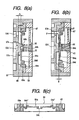
- an annular bent part 64d' having a approximately S-shape in section is formed in the support area side of the thin part 64a as shown in Fig. 8 (c) to keep the thin part 64a planar.
- Fig. 9 shows an embodiment of an apparatus for manufacturing the membrane valve.
- Molding dies A and B defining a mold cavity C corresponding in shape to the entire configuration of the membrane valve 53 are prepared.
- a first injection port L1 is provided at a radially outer side with respect to a ring part K, whereas a second injection port L2 is provided at a radially inner side.
- a hard polypropylene injection molding machine D1 and a soft polypropylene injection molding machine D2 are respectively connected via valves E1 and E2 the opened or closed time of which is controlled by a timer F.
- the molding dies A and B are rotated about an area to be formed as the ink flow port, and the first valve E1 is opened to inject hard polypropylene by predetermined quantity.
- the injected hard polypropylene is uniformly distributed in the outside by receiving centrifugal force and thus formed into an annular shape.
- the second valve E2 is opened to inject soft polypropylene, so that the soft polypropylene is molded into the shape of the mold dies while being closely contacted with the inside of the annular hard polypropylene.
- the filter is disposed to face the differential pressure valve mechanism, however, as shown in Fig. 10 , the similar effect is obtained even if the filter is disposed at a position not facing the differential pressure valve mechanism, for example, at a position below the differential pressure valve mechanism 50. That is, it suffices that the ink storage chamber 36 is communicated with one surface of a filter 70, and theothersurface of the filter 70 is communicated with the ink inflow port of the differential pressure valve mechanism 50 via a through-hole 71 formed in a thick portion of the casing 30.
- Figs. 11 (a) and 11 (b) respectively show the flow of ink in the above embodiment on the surface and the backface of the casing 30.
- the communication is established by flow (1) from the ink storage chamber 36 to the filter 70, flow (2) from the through-hole 71 via a passage formed in the casing to the inflow port 57d of the differential pressure valve mechanism 50, flow (3) passing through the membrane valve, flow (4) passing through a passage connecting the outflow ports 66 and 67 of the differential pressure valve mechanism 50 to the ink supply port 23 and flow (5) flowing the passage 44.
- a mark having a dot in a circle in the drawings shows flow perpendicular to the paper surface and toward a reader, whereas a mark having x in a circle shows flow perpendicularly to the paper surface and away from the reader.
- Fig. 12 shows an embodiment in which a main ink tank is directly connected to an ink supply unit.
- a main tank 80 is formed at the bottom of one side thereof with a connection port 81 to which an ink supply unit 90 is connected.
- the inside of the main tank 80 is divided into plural chambers, e.g. three firstto third ink chambers 84, 85 and 86 by two partitions 82 and 83 in this embodiment.
- the lower parts of the partition 82 and 83 are respectively formed with communicating ports 82a and 83a, where the upper surfaces 82b and 83b are set to be lower than the upper end of the connection port 81 and to be gradually lowered as they are apart from the connection port 81 for the ink supply unit.
- a sealing valve 87 is provided In the connection port 81, which has a projection 87a on the outer side and which is constantly biased toward the connection port 81 by a spring 88 having one end supported by the partition 82.
- the ink supply unit 90 is formed as a container forming an ink storage chamber 92 communicating with a tubular connection part 91 which can be inserted into the connection port 81 of the main tank 80 in a fluid-tight state.
- the connection part 91 is located at the lower part of the ink supply unit 90.
- the other surface opposite to the connection part 91 is provided with a differential pressure valve mechanism 100 described later.
- the connection part 91 is provided with an opening 91a into which the projection 87a of the sealing valve 87 can be inserted, and a valve 94 biased by a spring 93 is inserted therein so that the valve 94 can be moved back and forth.
- the spring 93 is set so that it is weaker than the spring 88 in the connection port 81.
- a communicating hole 96 is provided in an exposed wall 95 of the container defining the ink storage chamber 92 so that the communicating hole is located above the surface of ink in the ink storage chamber 92.
- a groove 97 is formed on the surface side of the wall, and connected to the communicating hole 96.
- An area where the communicating hole 96 is provided is sealed by a film 98a having repellent property and gas permeability to prevent ink from entering into the groove 97.
- the groove 97 is sealed by an air intercepting film 98b so that they form a passage communicating with the air.
- the differential pressure valve mechanism 100 is provided to a passage connecting the ink storage chamber 92 to an ink guidepath 4a of the recording head 4.
- a spherical convex valve seat 101 is formed on the lower end of the wall 95, and an ink inflow port 102 is formed in an area at the lower end thereof.
- a membrane valve 104 is biased by a coil spring 103 to come in contact with the center of the valve seat 101.
- the membrane valve 104 designed as a movable membrane is elastically deformable by the differential pressure of ink, and includes a membrane part 105 defining a spherical surface larger in radius than the valve seat 101, and an annular fixed part 106 integral with a fixed part 105a on the periphery of the membrane part 105.
- a first ink chamber 107 is defined between the membrane valve 104 and the valve seat 101.
- a protruded part 105b for engagement with the coil spring 103 is formed on the protruded side of the center of the membrane part 105, and a sealing part 105c for contact with the protruded end of the valve seat 101 is formed on the opposite back surface.
- An ink inflow port 105d is formed to penetrate these parts.
- the membrane valve 104 and the spring 103 are fixed by a valve fixing frame 109 provided with a recess for defining a second ink chamber 108.
- a passage connecting the second ink chamber 108 to the ink guidepath 4a of the recording head 4 is constructed by a through-hole formed through the valve fixing frame 109; or constructed such that grooves 109c and 109d are provided on the surface and the grooves 109c and 109d are sealed by a film (in this embodiment, a film 98b on the wall 95 forming the ink storage chamber 92 is used).
- the valve fixing frame 109 can be securely fixed by sharing the film 98b on the wall 95 of the ink storage chamber 92 in this manner.
- a reference number 110 denotes a filter provided to the ink inflow port 102, and 111 denotes packing for sealing.
- Such a differential pressure valve mechanism 100 can be assembled such that the spring 103 is fitted on a spring holding protrusion 109a of the valve fixing frame 109, the fixed part 105a of the membrane part 105 is aligned with a tapered groove 109b, the annular fixed part 106 is fitted between the outer periphery of the fixed part 105a and the groove 109b, and an integral unit of these are fixed to a recess 112.
- the membrane part 105 is pressed by the spring 103 to come in contact with the hemispherical valve seat 101 while being elastically deformed, and ink is supplied to the recording head 4 while maintaining differential pressure set by the spring 103 similarly to the aforementioned embodiments.
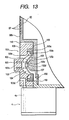
- connection port 81 of the main tank 80 is aligned with the connection part 91 of the ink supply unit 90 to establish a state in which air tight is kept by the packing 111 of the connection port 81 as shown in Fig. 14 (a) .
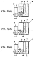
- ink in the second ink chamber 85 is consumed as shown in Fig. 15 (b) .
- ink in the third ink chamber 86 is consumed as shown in Fig. 15 (c) .
- the change of an ink level in the ink storage chamber 92 can be suppressed smaller than the change of an ink level in the main tank 80 in association with the ink consumption. Therefore, the variation of pressure can be reduced.
- the presence of the upper end 82b of the window 82a of the partition 82 can reduce the volume of air in the main tank 80, which does not communicate with the ambient air, and therefore the supply pressure of ink to the recording head can be stably kept.
- the vapor of ink in the ink storage chamber 92 is prevented from being evaporated in the ambient air by the capillary made up of the groove 97 and the film 98.
- the quantity of increased pressure in the ink storage chamber 92 caused by the ambient temperature increased is released to the ambient air via the capillary made up of the communicating hole 96 in the upper part of the ink storage chamber 92, the groove 97 and the film 98 so that pressure in the ink storage chamber 92 is released.
- Figs. 16 show other embodiments of the main tank.
- the main tank is divided into three ink chambers, however, as shown in Figs. 16(a) and 16 (b) , the main tank may be divided by three partitions or seven partitions, where the upper ends of communicating windows in the lower parts are positioned upper as the communicating windows are located closer to the connection port 81.
- the volume of each ink chamber is set smaller in this manner, dynamic pressure by ink flow of ink associated with the change from one chamber to another chamber can be reduced.
- Fig. 16 (c) if the lower end of the partition is tilted so that the lower end is located away from the connection port 81, dynamic pressure toward the connection port side by the ink flow of ink associated with the change from one ink chamber to another can be decreased.
- the upper part of each partition is horizontally extended to form a top plate, and a wall 80a to which these top plates are extended is made at least translucent. This makes it possible to visually recognize consumption of ink in each ink chamber from the side.
- Fig. 16 (e) even if communicating windows of the same height are used, approximately the similar effect is obtained.
- Figs. 17 (a) and 17 (b) show another embodiment of the present invention.
- a hollow needle 113 communicating with an ink storage chamber 92 is formed on the back surface of an ink supply unit 90, whereas an ink supply port 114 is formed in an ink cartridge 80 and sealed by a film 115 which the hollow needle 113 can pierce.
- a bottom face 116 having a slant face which is higher as the slant face is distanced further from the ink supply port 114 is formed.
- a first ink level detecting electrode 118 is arranged so that a common electrode 117 is located below the first ink level detecting electrode 118, and
- a second ink level detecting electrode 119 is arranged above the first ink level detecting electrode 118 and at a position where the second ink level detecting electrode 119 is exposed when no ink exists in the ink cartridge 80.
- the common electrode 117 is, preferably, arranged so that it is located below an ink inflow port 102.
- the hollow needle 113 when the hollow needle 113 is aligned with ink supply port 114 of the ink cartridge 80 and pushed thereto, the hollow needle 113 pierces the film 115 to permit ink in the ink cartridge 80 to flow into the ink storage chamber 92 of the ink supply unit 90.
- the second ink level detecting electrode 119 is exposed in the air, and conduction to the common electrode 117 is interrupted, whereby an ink end of the ink cartridge is detected.
- the first ink level detecting electrode 118 is exposed from ink, whereby an ink end of the ink storage chamber 92 is detected.
- Figs. 18 show another embodiment of the present invention.
- acommunicating passage 120 is formed, which is connected to an ink storage chamber 92 and extended to a position opposite to an ink chamber of an ink cartridge 80.
- the inkcartridge 80 is divided into plural chambers 84', 85' and 86' by partitions 82' and 83', and formed with ink supply ports 125.
- Each ink supply port 125 has a valve 124 constantly biased downwardly by a spring 123, which is located opposite to the hollow needle 121 in the case where the ink cartridge 80 is mounted to a holder 122.
- the ink supply ports 125 are sealed by a film 126.
- the leading end of the hollow needle 121 pierces the film 126 and pushes up the valve 124 to open a passage.
- the valve 124 is not supported by the hollow needle 121, and, as shown in Fig. 18 (b) , is elastically pressed onto the ink supply port 125 by the spring 123, to thereby prevent ink from flowing from the ink supply port 125.
- the ink supply port is sealed by the valve 124, however, as shown in Figs. 19 , an elastic plate 127, such as a rubber plate, having a through hole 127a located at a position opposite to the leading end of the hollow needle 121 may be disposed with its opening sealed by the film 126. This also provides the similar effect.
- an elastic plate 127 such as a rubber plate, having a through hole 127a located at a position opposite to the leading end of the hollow needle 121 may be disposed with its opening sealed by the film 126. This also provides the similar effect.
- the hollow needle 121 pierces the film 126 and then pushes into and widens the through-hole 127a of the elastic plate 127 to establish the communicate. In this state, as the periphery of the hollow needle 121 is sealed by the elastic plate 127, the leakage of ink, the evaporation of ink solvent, and further, the inflow of air are securely prevented.
- the hollow needle 121 has a small-diameter part 121 a on the leading end side, and a large-diameter part 121 b with a tapered leading end on the area contacting the elastic plate 127.
- the hollow needle 121 is withdrawn from the elastic plate 127. Therefore, the through-hole 127a is contracted to hold ink with capillary force, to thereby prevent ink from flowing outside.
- a process for supplying ink to the ink supply unit 3 via the tube 8 from the ink cartridge 5 installed in a body as shown in Fig. 1 will be described in detail below.
- the ink inlet 9 of the ink supply unit 3 is communicated with the ink cartridge 5 through a tube 8' extended from the ink supplementing unit 7 and the tube 8 via a coupling 130, and the air open port 21 is connected to the pump unit 10 through tubes 11' extended from the ink supplementing unit 7 and the tube 11 via a coupling 131.
- ink can be injected into the ink storage chamber 36 without allowing air bubbles to enter into the valve chamber 37.
- the ink inlet 9 is sealed, and further the pump unit 10 of the ink refilling unit 7 is operated to reduce the pressure of ink in the ink storage chamber 36, so that ink in the ink storage chamber can be fully degassed.
- the differential pressure valve mechanism 50 connected between the ink storage chamber 36 and the recording head 4 acts as a check valve, no air flows in via the recording head 4 and unnecessary high suction force does not act on the recording head.
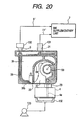
- the recording head 4 is sealed by capping means 132, and a suction pump 133 is operated, so that so-called ejection recovery processing is executed.
- the capping means 132 When negative pressure is applied by the capping means 132, the negative pressure acts on the differential pressure valve mechanism 50 from the groove 44 forming an ink passage via the ink guidepath 4a. Since the differential pressure valve mechanism 50 is opened when pressure on the side of the recording head 4 is decreased as described above, ink in the valve chamber37 is filtered by the filter 56 (see Fig. 5 ), passes through the differential pressure regulating mechanism 50 and flows into the recording head 4.
- the ink supply unit comprises a differential pressure valve including a coil spring and a movable membrane adapted to elastically contact a valve seat by means of the coil spring. Since pressure of ink supplied to an ink-jet recording head is kept negative by the coil spring, the fluctuation of the movable membrane associated with movement of a carriage can be suppressed by the coil spring. Therefore, ink can be stably supplied to the recording head while maintaining suitable negative pressure.
Landscapes
- Ink Jet (AREA)
- Particle Formation And Scattering Control In Inkjet Printers (AREA)
- Recording Measured Values (AREA)
- Pens And Brushes (AREA)
- Disintegrating Or Milling (AREA)
- Photographic Developing Apparatuses (AREA)
Claims (35)
- Unité d'alimentation en encre (3, 90), dans laquelle :une soupape à pression différentielle incluant un ressort hélicoïdal (51 ,103) et une membrane mobile (53) adaptée pour venir en contact élastiquement avec un siège de soupape (57c) sous l'action dudit ressort hélicoïdal (51, 103) est logée dans un récipient comportant une chambre de stockage d'encre (36, 92) communiquant avec un orifice d'alimentation en encre (23) adapté pour être raccordé à une tête d'enregistrement à jet d'encre (4), où ladite membrane mobile (53) est située entre ledit siège de soupape (57c) et ledit ressort hélicoïdal (51, 103),ladite membrane mobile (53) est disposée verticalement lorsque ladite unité d'alimentation en encre (3, 90) est montée sur un chariot (1),etladite membrane mobile (53) est disposée parallèlement à un plan perpendiculaire à une direction dans laquelle ledit chariot (1) est déplacé.
- Unité d'alimentation en encre (3, 90) selon la revendication 1, dans laquelle :ladite soupape à pression différentielle inclut un élément de membrane élastique en forme de disque (54) comportant en son centre un orifice (54a) de passage de l'encre, un siège de soupape (57c) situé sur un côté amont de l'écoulement d'encre et tourné vers ledit orifice d'écoulement d'encre (54a) et un ressort hélicoïdal (51) situé sur un côté aval et repoussant ledit orifice d'écoulement d'encre (54a) dudit élément de membrane élastique (54) sur ledit siège de soupape (57c).
- Unité d'alimentation en encre (3, 90) selon la revendication 1, dans laquelle :ladite membrane mobile (53) reçoit une pression dudit ressort hélicoïdal (51, 103) par l'intermédiaire d'un dispositif de retenue (52).
- Unité d'alimentation en encre (3, 90) selon l'une quelconque des revendications 1 à 3, dans laquelle :ledit boîtier (30) inclut un boîtier en forme de cadre comportant une fenêtre au niveau de sa surface latérale, et un film (31) d'interception
de l'air qui ferme de façon étanche ladite fenêtre. - Unité d'alimentation en encre (3, 90) selon la revendication 1, dans laquelle :ladite chambre de stockage d'encre (36) communique avec un air ambiant par l'intermédiaire d'un capillaire formé dans ledit récipient.
- Unité d'alimentation en encre (3, 90) selon la revendication 5, dans laquelle :ledit capillaire inclut une gorge (97) formée sur une paroi supérieure de ladite chambre de stockage d'encre (36, 92) et un film d'interception de l'air (98) fermant de façon étanche ladite gorge (97).
- Unité d'alimentation en encre (3, 90) selon la revendication 5, dans laquelle :ledit capillaire inclut une gorge (97) formée sur une paroi latérale de ladite chambre de stockage d'encre (36, 92), et un film d'interception de l'air (98) fermant de façon étanche ladite gorge (97).
- Unité d'alimentation en encre (3, 90) selon la revendication 1, dans laquelle :ladite membrane mobile (53) inclut une partie mobile (54, 105) formée d'un matériau mou et une partie de fixation (55, 106) formée d'un matériau dur et fixée à une périphérie de ladite partie mobile (54, 105).
- Unité d'alimentation en encre (3, 90) selon la revendication 8, dans laquelle :une partie de support est formée sur une périphérie extérieure de ladite partie mobile (54); etladite partie mobile (54, 105) est connectée à ladite partie de fixation (55, 106) au moyen de ladite partie de support.
- Unité d'alimentation en encre (3, 90) selon la revendication 1, dans laquelle :une partie mobile (54) est prévue sur ladite membrane mobile (53); etune partie de support est formée sur une périphérie extérieure de ladite partie mobile (54, 105).
- Unité d'alimentation en encre (3, 90) selon la revendication 1, 8 ou 10, dans laquelle :ladite membrane mobile (53) est pourvue d'une partie mobile (54, 105); etune partie annulaire coudée est formée au voisinage d'une périphérie extérieure de ladite partie mobile (54, 105).
- Unité d'alimentation en encre (3, 90) selon la revendication 10, dans laquelle :ladite partie mobile (54, 105) est située approximativement au centre dans le sens de l'épaisseur de ladite partie de support.
- Unité d'alimentation en encre (3, 90) selon la revendication 8 ou 10, dans laquelle :une zone centrale de ladite partie mobile (54, 105) est décalée depuis une zone périphérique de celle-ci.
- Unité d'alimentation en encre (3, 90) selon la revendication 8, dans laquelle :ladite partie de fixation (55, 106) est pourvue, sur son côté tourné vers ledit siège de soupape (57c), d'une partie formant bride; etune position de ladite partie mobile (54, 105) dans la direction de son épaisseur est réglée par ladite partie formant bride.
- Unité d'alimentation en encre (3, 90) selon la revendication 1, dans laquelle :un filtre (70) est disposé sur un côté amont par rapport à ladite soupape à pression différentielle.
- Unité d'alimentation en encre (3, 90) selon la revendication 1, dans laquelle :ledit ressort hélicoïdal (51, 103) est placé en contact avec ladite membrane mobile (54, 105) par l'intermédiaire d'un dispositif de retenue (52) possédant un trou de passage de l'encre situé de manière à faire face à un orifice d'écoulement d'encre (54a) de ladite membrane mobile (54, 105).
- Unité d'alimentation en encre (3, 90) selon la revendication 1, dans laquelle ;
ledit siège de soupape (57c) est formé en tant que surface sphérique qui fait saillie en direction de ladite membrane mobile (54, 105). - Unité d'alimentation en encre (3, 90) selon la revendication 1, dans laquelle ;
une partie saillante est formée sur une surface dudit siège de soupape (57c) où elle est en contact avec ladite membrane mobile. - Unité d'alimentation en encre (3, 90) selon l'une quelconque des revendications 1 à 18, dans laquelle :ledit siège de soupape (57c) est formé en tant que partie saillante possédant une surface plane sur un côté tourné vers ladite soupape mobile (54, 105).
- Unité d'alimentation en encre (3, 90) selon la revendication 1, dans laquelle :ladite soupape mobile (54, 105) inclut une partie mobile en forme de disque formée d'un matériau haut polymère souple et pourvue, sur sa périphérie extérieure, d'une partie épaisse, et une partie annulaire de support formée d'un matériau polymère dur et pourvue, sur son côté tourné vers le siège de soupape, d'une partie formant bride; etledit siège de soupape (57c) est formé en tant que partie saillante définissant une surface plane sur un côté de soupape mobile et possédant une épaisseur approximativement égale à celle de ladite partie formant bride.
- Unité d'alimentation en encre (3, 90) selon la revendication 20, dans laquelle :ladite surface plane de ladite partie saillante et ladite partie formant bride sont situées dans le même plan.
- Unité d'alimentation en encre (3, 90) selon l'une quelconque des revendications 1 à 21, dans laquelle :ladite soupape à pression différentielle inclut une membrane mobile en forme de disque (54, 105) comportant en son centre un orifice de circulation de l'encre, un ressort hélicoïdal (51, 103) en contact avec ladite membrane mobile (54, 105) et un siège de soupape (57c) formé en tant que partie saillante définissant une surface plane sur un côté de la membrane mobile et possédant un bord extérieur situé à l'extérieur d'une périphérie extérieure dudit ressort hélicoïdal (51, 103).
- Unité d'alimentation en encre (3, 90) selon la revendication 22, dans laquelle :ladite membrane (54, 105) est formée du côté de son siège de soupape avec une surface plane et, sur la surface opposée, avec une partie saillante qui supporte ledit ressort hélicoïdal (51, 103).
- Unité d'alimentation en encre (3, 90) selon la revendication 1, dans laquelle ;
un orifice d'injection d'encre est prévu sur une surface supérieure dudit récipient et est placé en communication avec une partie inférieure de ladite chambre de stockage d'encre par l'intermédiaire d'un passage isolé vis-à-vis de ladite chambre de stockage d'encre (36, 92). - Unité d'alimentation en encre (3, 90) selon la revendication 1, dans laquelle :un orifice d'injection d'encre est prévu sur une surface supérieure dudit récipient et est placé en communication avec une partie inférieure de ladite chambre de stockage d'encre (36, 92) au voisinage d'un côté amont de ladite soupape à pression différentielle par l'intermédiaire d'un passage isolé vis-à-vis de ladite chambre de stockage d'encre.
- Unité d'alimentation en encre (3, 90) selon la revendication 1, dans laquelle :ladite chambre de stockage d'encre et une zone dans laquelle ladite soupape à pression différentielle est logée sont séparées par une paroi (33) pourvue au niveau de sa partie inférieure d'un trou de communication (21a) ;une pluralité d'électrodes (117, 118, 119) pour détecter un niveau d'encre sont prévues dans ladite chambre de stockage d'encre (36, 92) ; etau moins l'une desdites électrodes (117, 118, 119) est disposée au-dessus dudit trou de communication (21a).
- Unité d'alimentation en encre (3, 90) selon la revendication 1, dans laquelle :ladite soupape à pression différentielle inclut une membrane mobile sphérique (54, 105) pourvue en son centre d'un orifice d'écoulement d'encre (54a), un ressort hélicoïdal (51, 103) en contact avec ladite membrane mobile (54, 105) et un siège de soupape (57c) possédant une partie sphérique qui fait saillie en direction de ladite membrane mobile (54, 105).
- Unité d'alimentation en encre (3, 90) selon la revendication 27, dans laquelle :ledit siège de soupape (57c) est formé sur une paroi formant ladite chambre de stockage d'encre.
- Unité d'alimentation en encre (3, 90) selon la revendication 27, dans laquelle :ladite membrane mobile (54, 105) et ledit ressort hélicoïdal (51, 103) sont fixés à une paroi formant ladite chambre de stockage d'encre par un cadre de fixation de soupape.
- Unité d'alimentation en encre (3, 90) selon la revendication 29, dans laquelle :ledit cadre de fixation de soupape est pourvu d'un passage communiquant avec une tête d'enregistrement (4).
- Unité d'alimentation en encre (3, 90) selon la revendication 30, dans laquelle :ledit passage inclut une gorge (97) dans ledit cadre de fixation de soupape, et un film d'interception d'air (98) réalisant l'étanchéité de ladite gorge.
- Unité d'alimentation en encre (3, 90) selon la revendication 5, dans laquelle :un élément de film présentant à la fois une perméabilité aux gaz et une propriété de répulsion des gaz est intercalé entre ledit capillaire et ladite chambre de stockage d'encre (36, 92).
- Unité d'alimentation en encre (3, 90) selon la revendication 1, dans laquelle :un moyen (118, 119) de détection du niveau d'encre est agencé sur un côté amont par rapport à ladite soupape à pression différentielle.
- Unité d'alimentation en encre (3, 90) selon la revendication 15, dans laquelle :un moyen (118, 119) de détection du niveau d'encre est disposé sur un côté amont par rapport audit filtre (70).
- Unité d'alimentation en encre (3, 90) selon la revendication 15, dans laquelle
un moyen (118, 119) de détection du niveau d'encre est agencé de telle sorte que ledit filtre (70) n'est pas exposé lorsqu'un épuisement de l'encre est détecté.
Priority Applications (8)
| Application Number | Priority Date | Filing Date | Title |
|---|---|---|---|
| EP20090165877 EP2108513B1 (fr) | 1998-07-15 | 1999-07-15 | Unité d'alimentation d'encre |
| DE1999615999 DE69915999T3 (de) | 1998-07-15 | 1999-07-15 | Tintenzufuhreinheit |
| EP20070005031 EP1792737B9 (fr) | 1998-07-15 | 1999-07-15 | Unité d'alimentation d'encre |
| ES07024971T ES2358054T3 (es) | 1998-07-15 | 1999-07-15 | Unidad de suministro de tinta. |
| EP20030012124 EP1348561B1 (fr) | 1998-07-15 | 1999-07-15 | Dispositif d'enregistrement à jet d'encre |
| ES09165877T ES2362979T3 (es) | 1998-07-15 | 1999-07-15 | Unidad de suministro de tinta. |
| EP20070024971 EP1914080B1 (fr) | 1998-07-15 | 1999-07-15 | Réservoir d'encre |
| EP20040001663 EP1440808B2 (fr) | 1998-07-15 | 1999-07-15 | Unite d'alimentation en encre |
Applications Claiming Priority (5)
| Application Number | Priority Date | Filing Date | Title |
|---|---|---|---|
| JP20037798 | 1998-07-15 | ||
| JP20037798 | 1998-07-15 | ||
| JP28410498 | 1998-10-06 | ||
| JP28410498 | 1998-10-06 | ||
| PCT/JP1999/003839 WO2000003877A1 (fr) | 1998-07-15 | 1999-07-15 | Enregistreur a jet d'encre avec son module d'alimentation en encre |
Related Child Applications (9)
| Application Number | Title | Priority Date | Filing Date |
|---|---|---|---|
| EP20040001663 Division EP1440808B2 (fr) | 1998-07-15 | 1999-07-15 | Unite d'alimentation en encre |
| EP20040001663 Division-Into EP1440808B2 (fr) | 1998-07-15 | 1999-07-15 | Unite d'alimentation en encre |
| EP20090165877 Division-Into EP2108513B1 (fr) | 1998-07-15 | 1999-07-15 | Unité d'alimentation d'encre |
| EP20070005031 Division-Into EP1792737B9 (fr) | 1998-07-15 | 1999-07-15 | Unité d'alimentation d'encre |
| EP20030012124 Division EP1348561B1 (fr) | 1998-07-15 | 1999-07-15 | Dispositif d'enregistrement à jet d'encre |
| EP20030012124 Division-Into EP1348561B1 (fr) | 1998-07-15 | 1999-07-15 | Dispositif d'enregistrement à jet d'encre |
| EP20070024971 Division-Into EP1914080B1 (fr) | 1998-07-15 | 1999-07-15 | Réservoir d'encre |
| EP09011205 Division-Into | 2009-09-01 | ||
| EP10185758 Division-Into | 2010-10-01 |
Publications (4)
| Publication Number | Publication Date |
|---|---|
| EP1016533A1 EP1016533A1 (fr) | 2000-07-05 |
| EP1016533A4 EP1016533A4 (fr) | 2001-10-04 |
| EP1016533B1 EP1016533B1 (fr) | 2004-03-31 |
| EP1016533B3 true EP1016533B3 (fr) | 2011-08-31 |
Family
ID=26512149
Family Applications (6)
| Application Number | Title | Priority Date | Filing Date |
|---|---|---|---|
| EP20070005031 Expired - Lifetime EP1792737B9 (fr) | 1998-07-15 | 1999-07-15 | Unité d'alimentation d'encre |
| EP20090165877 Expired - Lifetime EP2108513B1 (fr) | 1998-07-15 | 1999-07-15 | Unité d'alimentation d'encre |
| EP20070024971 Expired - Lifetime EP1914080B1 (fr) | 1998-07-15 | 1999-07-15 | Réservoir d'encre |
| EP19990929867 Expired - Lifetime EP1016533B3 (fr) | 1998-07-15 | 1999-07-15 | Module d'alimentation en encre |
| EP20030012124 Expired - Lifetime EP1348561B1 (fr) | 1998-07-15 | 1999-07-15 | Dispositif d'enregistrement à jet d'encre |
| EP20040001663 Expired - Lifetime EP1440808B2 (fr) | 1998-07-15 | 1999-07-15 | Unite d'alimentation en encre |
Family Applications Before (3)
| Application Number | Title | Priority Date | Filing Date |
|---|---|---|---|
| EP20070005031 Expired - Lifetime EP1792737B9 (fr) | 1998-07-15 | 1999-07-15 | Unité d'alimentation d'encre |
| EP20090165877 Expired - Lifetime EP2108513B1 (fr) | 1998-07-15 | 1999-07-15 | Unité d'alimentation d'encre |
| EP20070024971 Expired - Lifetime EP1914080B1 (fr) | 1998-07-15 | 1999-07-15 | Réservoir d'encre |
Family Applications After (2)
| Application Number | Title | Priority Date | Filing Date |
|---|---|---|---|
| EP20030012124 Expired - Lifetime EP1348561B1 (fr) | 1998-07-15 | 1999-07-15 | Dispositif d'enregistrement à jet d'encre |
| EP20040001663 Expired - Lifetime EP1440808B2 (fr) | 1998-07-15 | 1999-07-15 | Unite d'alimentation en encre |
Country Status (7)
| Country | Link |
|---|---|
| US (6) | US7090341B1 (fr) |
| EP (6) | EP1792737B9 (fr) |
| JP (5) | JP3874067B2 (fr) |
| AT (5) | ATE496775T1 (fr) |
| DE (7) | DE29924902U1 (fr) |
| ES (6) | ES2330682T3 (fr) |
| WO (1) | WO2000003877A1 (fr) |
Cited By (1)
| Publication number | Priority date | Publication date | Assignee | Title |
|---|---|---|---|---|
| US11623450B2 (en) | 2018-05-15 | 2023-04-11 | Hewlett-Packard Development Company, L.P. | Output mechanism for a fluid container |
Families Citing this family (164)
| Publication number | Priority date | Publication date | Assignee | Title |
|---|---|---|---|---|
| JP3582592B2 (ja) * | 2001-04-03 | 2004-10-27 | セイコーエプソン株式会社 | インクカートリッジ、及びインクジェット記録装置 |
| JPH08174860A (ja) | 1994-10-26 | 1996-07-09 | Seiko Epson Corp | インクジェットプリンタ用インクカートリッジ |
| DE69733176T2 (de) | 1996-02-21 | 2006-02-16 | Seiko Epson Corp. | Tintenkartusche |
| JP4141523B2 (ja) | 1997-03-19 | 2008-08-27 | セイコーエプソン株式会社 | インク供給流路の弁装置 |
| ATE496775T1 (de) | 1998-07-15 | 2011-02-15 | Seiko Epson Corp | Tintenbehälter |
| JP3791294B2 (ja) * | 2000-03-27 | 2006-06-28 | セイコーエプソン株式会社 | インクジェット記録装置の接続ユニット |
| CN1184076C (zh) | 2000-02-16 | 2005-01-12 | 精工爱普生株式会社 | 喷墨打印机用墨盒 |
| US6935730B2 (en) | 2000-04-03 | 2005-08-30 | Unicorn Image Products Co. Ltd. Of Zhuhai | One-way valve, valve unit assembly, and ink cartridge using the same |
| US20030107626A1 (en) * | 2000-08-16 | 2003-06-12 | Xiao Qingguo | Ink cartridge having bellows valve, ink filling method and apparatus used thereof |
| WO2002004217A1 (fr) * | 2000-07-07 | 2002-01-17 | Seiko Epson Corporation | Unite d'alimentation en encre pour enregistreur a jet d'encre et obturateur a diaphragme |
| DE60125252T2 (de) | 2000-10-20 | 2007-06-28 | Seiko Epson Corp. | Tintenpatrone |
| ES2306687T3 (es) * | 2000-10-20 | 2008-11-16 | Seiko Epson Corporation | Cartucho de tinta para un dispositivo de registro de inyeccion de tinta. |
| JP4871222B2 (ja) * | 2000-10-20 | 2012-02-08 | セイコーエプソン株式会社 | インクカートリッジ |
| CA2359434C (fr) | 2000-10-20 | 2005-05-03 | Seiko Epson Corporation | Imprimante "ink jet" et cartouche a encre |
| US6508545B2 (en) | 2000-12-22 | 2003-01-21 | Hewlett-Packard Company | Apparatus for providing ink to an ink jet print head |
| JP4576858B2 (ja) * | 2001-02-09 | 2010-11-10 | セイコーエプソン株式会社 | インクカートリッジ |
| CA2386730C (fr) * | 2001-05-17 | 2011-06-14 | Seiko Epson Corporation | Cartouche d'encre, et methode de remplissage |
| ATE425007T1 (de) * | 2001-05-17 | 2009-03-15 | Seiko Epson Corp | Tinteneinspritzverfahren für eine tintenkartusche |
| EP1669200B1 (fr) | 2001-05-17 | 2008-11-19 | Seiko Epson Corporation | Cartouche d'encre |
| ATE367271T1 (de) | 2001-05-17 | 2007-08-15 | Seiko Epson Corp | Tintenkartusche und tintenstrahlaufzeichnungsgerät das diese verwendet |
| CN2595567Y (zh) | 2001-05-17 | 2003-12-31 | 精工爱普生株式会社 | 墨盒 |
| JP3606282B2 (ja) | 2001-11-12 | 2005-01-05 | セイコーエプソン株式会社 | 液体噴射装置 |
| US7278718B2 (en) | 2002-01-22 | 2007-10-09 | Seiko Epson Corporation | Liquid injecting apparatus |
| JP3879573B2 (ja) * | 2002-04-12 | 2007-02-14 | セイコーエプソン株式会社 | 弁装置 |
| JP3876750B2 (ja) * | 2002-04-12 | 2007-02-07 | セイコーエプソン株式会社 | 弁装置 |
| CN1287106C (zh) | 2002-04-12 | 2006-11-29 | 精工爱普生株式会社 | 阀门装置 |
| CN2544940Y (zh) * | 2002-04-27 | 2003-04-16 | 珠海纳思达电子科技有限公司 | 打印机墨盒 |
| GB0321821D0 (en) * | 2003-09-17 | 2003-10-15 | Opportunity Europ Limimted | Ink-jet cartridges |
| GB2410111C (en) * | 2002-07-02 | 2006-06-12 | Autoliv Dev | A triggering unit |
| JP3991853B2 (ja) | 2002-09-12 | 2007-10-17 | セイコーエプソン株式会社 | インクカートリッジ |
| RU2259924C2 (ru) * | 2002-09-12 | 2005-09-10 | Сейко Эпсон Корпорейшн | Картридж для чернил (варианты), устройство и способ регулировки потока жидкости из картриджа |
| US6984030B2 (en) * | 2002-11-13 | 2006-01-10 | Seiko Epson Corporation | Ink cartridge and method of regulating fluid flow |
| EP1852260A1 (fr) * | 2002-12-10 | 2007-11-07 | Seiko Epson Corporation | Cartouche de liquide |
| JP4535203B2 (ja) * | 2002-12-13 | 2010-09-01 | セイコーエプソン株式会社 | 液体カートリッジ |
| KR100487585B1 (ko) * | 2002-12-20 | 2005-05-03 | 주식회사 프린톤 | 잉크젯 프린터용 잉크 카트리지의 잉크리필방법 |
| JPWO2004082945A1 (ja) | 2003-03-18 | 2006-06-22 | セイコーエプソン株式会社 | 液体噴射装置 |
| CA2745944C (fr) * | 2003-03-26 | 2012-07-31 | Seiko Epson Corporation | Reservoir a liquide |
| JP3848295B2 (ja) * | 2003-05-16 | 2006-11-22 | キヤノン株式会社 | インクタンク |
| JP4261983B2 (ja) * | 2003-05-22 | 2009-05-13 | キヤノン株式会社 | インクタンク |
| JP4550400B2 (ja) * | 2003-11-13 | 2010-09-22 | セイコーエプソン株式会社 | 液体カートリッジ |
| JP4492144B2 (ja) * | 2003-12-08 | 2010-06-30 | ブラザー工業株式会社 | インクジェット記録装置 |
| US7354135B2 (en) | 2004-03-16 | 2008-04-08 | Seiko Epson Corporation | Waste liquid collecting method, liquid injecting apparatus and cartridge set |
| US20050219281A1 (en) | 2004-03-24 | 2005-10-06 | Takeo Seino | Attachment and liquid supplying |
| JP2005271540A (ja) * | 2004-03-26 | 2005-10-06 | Seiko Epson Corp | インクジェットヘッドユニット |
| JP4715129B2 (ja) * | 2004-06-01 | 2011-07-06 | セイコーエプソン株式会社 | 吐出ヘッド装置、液滴吐出装置および電気光学装置の製造方法 |
| US7367659B2 (en) * | 2004-08-27 | 2008-05-06 | Brother Kogyo Kabushiki Kaisha | Ink jet printer alternately utilizing a pair of in cartridges |
| CN2726881Y (zh) * | 2004-09-06 | 2005-09-21 | 聂瑞权 | 喷墨打印机墨盒 |
| JP4258462B2 (ja) * | 2004-11-19 | 2009-04-30 | セイコーエプソン株式会社 | 圧力調整弁、機能液供給装置および描画装置 |
| GB2424620B (en) * | 2005-03-30 | 2007-02-14 | Monitek Electronics Ltd | Ink cartridge |
| CN2832528Y (zh) * | 2005-08-02 | 2006-11-01 | 珠海纳思达电子科技有限公司 | 一种通用打印机墨盒 |
| CN200960761Y (zh) * | 2005-09-04 | 2007-10-17 | 珠海纳思达电子科技有限公司 | 一种分体式墨盒 |
| US7810916B2 (en) * | 2005-09-29 | 2010-10-12 | Brother Kogyo Kabushiki Kaisha | Ink cartridges |
| US7837311B2 (en) * | 2005-09-29 | 2010-11-23 | Brother Kogyo Kabushiki Kaisha | Ink cartridges |
| US8025376B2 (en) * | 2005-09-29 | 2011-09-27 | Brother Kogyo Kabushiki Kaisha | Ink cartridges |
| US7828421B2 (en) * | 2005-09-29 | 2010-11-09 | Brother Kogyo Kabushiki Kaisha | Ink cartridge arrangements |
| US7682004B2 (en) * | 2005-09-29 | 2010-03-23 | Brother Kogyo Kabushiki Kaisha | Ink cartridges |
| US7316471B2 (en) * | 2005-09-29 | 2008-01-08 | Brother Kogyo Kabushiki Kaishi | Ink cartridges |
| US7775645B2 (en) * | 2005-09-29 | 2010-08-17 | Brother Kogyo Kabushiki Kaisha | Methods of forming cartridges, such as ink cartridges |
| US7553007B2 (en) * | 2005-09-29 | 2009-06-30 | Brother Kogyo Kabushiki Kaisha | Ink cartridges |
| USD539340S1 (en) * | 2005-10-28 | 2007-03-27 | Graphtec Corporation | Print head for printer |
| JP2007160926A (ja) | 2005-11-18 | 2007-06-28 | Seiko Epson Corp | 液滴吐出装置 |
| USD547370S1 (en) * | 2005-11-18 | 2007-07-24 | Brother Industries, Ltd. | Frame of ink cartridge |
| KR20070057025A (ko) | 2005-11-29 | 2007-06-04 | 세이코 엡슨 가부시키가이샤 | 밸브 장치를 구비한 액체 분사 장치 |
| JP2007182055A (ja) * | 2005-12-06 | 2007-07-19 | Seiko Epson Corp | 液体収容容器 |
| JP4899683B2 (ja) | 2005-12-13 | 2012-03-21 | セイコーエプソン株式会社 | 差圧弁ユニット |
| US7954662B2 (en) * | 2005-12-28 | 2011-06-07 | Canon Kabushiki Kaisha | Liquid storage container |
| JP4910749B2 (ja) * | 2006-02-15 | 2012-04-04 | セイコーエプソン株式会社 | 検出方法及び故障検出装置 |
| EP1820653A3 (fr) * | 2006-02-15 | 2008-07-09 | Seiko Epson Corporation | Conteneur de liquide |
| US7618135B2 (en) * | 2006-03-22 | 2009-11-17 | Hewlett-Packard Development Company, L.P. | Inkjet printing system with push priming |
| JP4797748B2 (ja) * | 2006-03-30 | 2011-10-19 | ブラザー工業株式会社 | インクカートリッジ |
| JP2007301917A (ja) * | 2006-05-15 | 2007-11-22 | Sony Corp | 液体貯留容器及び液体吐出装置 |
| CL2007002335A1 (es) * | 2006-08-11 | 2008-04-18 | Seiko Epson Corp | Un metodo para inyectar un liquido en un envase de liquido montado en forma removible en un dispositivo consumidor de liquido que tiene camaras contenedoras de liquido, en donde se forma un orificio de inyeccion, se inyecta una cantidad de liquido, y |
| TWI415689B (zh) * | 2006-08-17 | 2013-11-21 | 半導體能源研究所股份有限公司 | 成膜方法、液滴排出方法以及液滴排出裝置 |
| JP4995674B2 (ja) * | 2006-10-05 | 2012-08-08 | エスアイアイ・プリンテック株式会社 | 圧力緩衝器及びインクジェットヘッド並びにインクジェット式記録装置 |
| DE102006050161A1 (de) * | 2006-10-25 | 2008-04-30 | Robert Bosch Gmbh | Reservoir für einen Kraftstoffbehälter |
| US7416290B2 (en) | 2007-01-30 | 2008-08-26 | Brother Kogyo Kabushiki Kaisha | Ink cartridges |
| JP4858191B2 (ja) | 2007-01-30 | 2012-01-18 | ブラザー工業株式会社 | インクカートリッジ及びカートリッジ収容装置 |
| JP4867681B2 (ja) * | 2007-01-31 | 2012-02-01 | ブラザー工業株式会社 | 液体圧調整装置 |
| US8162453B2 (en) * | 2007-02-14 | 2012-04-24 | Fujifilm Corporation | Inkjet recording apparatus and ink supply method |
| JP4862683B2 (ja) | 2007-02-19 | 2012-01-25 | ブラザー工業株式会社 | インクカートリッジ |
| US7950764B2 (en) * | 2007-03-16 | 2011-05-31 | Seiko Epson Corporation | Pressure regulating mechanism and liquid ejecting apparatus |
| JP4798032B2 (ja) * | 2007-03-20 | 2011-10-19 | ブラザー工業株式会社 | 液体容器、及びこれを備えたインクカートリッジ |
| JP4345833B2 (ja) * | 2007-03-20 | 2009-10-14 | セイコーエプソン株式会社 | 液体吐出装置および液体供給方法 |
| JP4798033B2 (ja) * | 2007-03-20 | 2011-10-19 | ブラザー工業株式会社 | 液体充填方法 |
| JP2008230137A (ja) * | 2007-03-22 | 2008-10-02 | Fujifilm Corp | 液体吐出ヘッドの背圧調整装置 |
| KR101430023B1 (ko) * | 2007-04-12 | 2014-08-14 | 인트린직 아이디 비브이 | 기능의 제어된 활성화 |
| US20090009541A1 (en) | 2007-07-02 | 2009-01-08 | Seiko Epson Corporation | Liquid discharging apparatus and method of discharging liquid |
| US8789905B2 (en) * | 2007-07-02 | 2014-07-29 | Seiko Epson Corporation | Liquid discharging apparatus and method of discharging liquid |
| JP2009023251A (ja) * | 2007-07-20 | 2009-02-05 | Canon Inc | インクジェット記録装置 |
| JP5256665B2 (ja) * | 2007-08-13 | 2013-08-07 | セイコーエプソン株式会社 | インクカートリッジおよび印刷装置 |
| USD712465S1 (en) * | 2007-10-12 | 2014-09-02 | Videojet Technologies Inc. | Ink cartridge |
| DE602008002550D1 (de) * | 2008-02-28 | 2010-10-28 | Brother Ind Ltd | Tintenpatrone und System mit einer solchen Tintenpatrone |
| ATE461050T1 (de) * | 2008-02-28 | 2010-04-15 | Brother Ind Ltd | Tintenpatrone |
| WO2009116298A1 (fr) * | 2008-03-21 | 2009-09-24 | セイコーエプソン株式会社 | Récipient pour liquide et soupape à membrane |
| USD610607S1 (en) * | 2008-05-23 | 2010-02-23 | Fujifilm Corporation | Inkjet recording device |
| JP5471260B2 (ja) | 2008-11-14 | 2014-04-16 | セイコーエプソン株式会社 | 液体収容容器 |
| JP5790806B2 (ja) * | 2008-11-14 | 2015-10-07 | セイコーエプソン株式会社 | 液体収容容器 |
| JP5104771B2 (ja) | 2009-01-29 | 2012-12-19 | ブラザー工業株式会社 | インクジェットヘッドおよびそれを備えたプリンタ |
| JP5343611B2 (ja) * | 2009-02-23 | 2013-11-13 | セイコーエプソン株式会社 | 圧力調整弁およびこれを備えた液滴吐出装置 |
| US8113612B2 (en) * | 2009-02-27 | 2012-02-14 | Hewlett-Packard Development Company, L.P. | Ink delivery system |
| JP2010214721A (ja) * | 2009-03-16 | 2010-09-30 | Seiko Epson Corp | 液体収容容器 |
| JP5300565B2 (ja) * | 2009-04-07 | 2013-09-25 | キヤノン株式会社 | 弁機構およびこれを備えた排気装置、ならびにインクジェット記録装置 |
| JP5272947B2 (ja) * | 2009-07-27 | 2013-08-28 | 株式会社リコー | 画像形成装置 |
| CN101992602B (zh) * | 2009-08-24 | 2012-09-19 | 珠海中润靖杰打印机耗材有限公司 | 一种用于喷墨打印机的墨盒 |
| JP6112125B2 (ja) * | 2010-02-15 | 2017-04-12 | セイコーエプソン株式会社 | 液体噴射装置 |
| JP5703679B2 (ja) | 2010-02-15 | 2015-04-22 | セイコーエプソン株式会社 | 液体噴射装置及び液体噴射装置のメンテナンス方法 |
| US20110205318A1 (en) * | 2010-02-24 | 2011-08-25 | Price Brian G | Ink tank check valve for pressure regulation |
| JP5488052B2 (ja) | 2010-03-01 | 2014-05-14 | セイコーエプソン株式会社 | 液体噴射装置 |
| JP5482339B2 (ja) * | 2010-03-17 | 2014-05-07 | 株式会社リコー | 液滴吐出装置及び画像形成装置 |
| JP5340240B2 (ja) | 2010-04-02 | 2013-11-13 | キヤノン株式会社 | タンクおよびこれを備えたプリンタ |
| CN102869516A (zh) * | 2010-04-22 | 2013-01-09 | 吉特株式会社 | 阀机构、墨水控制机构、墨水贮存容器 |
| JP2012121275A (ja) * | 2010-12-10 | 2012-06-28 | Jit Kk | インク制御機構、インク貯蔵容器 |
| JP5619469B2 (ja) * | 2010-04-22 | 2014-11-05 | ジット株式会社 | 弁機構、インク貯蔵容器 |
| JP5573397B2 (ja) * | 2010-06-17 | 2014-08-20 | ブラザー工業株式会社 | インクカートリッジ及び画像記録装置 |
| DE112010005723T5 (de) * | 2010-07-06 | 2013-05-16 | Hewlett-Packard Development Co., L.P. | Flüssigkeitszuführungssystem |
| US8733913B2 (en) | 2010-07-06 | 2014-05-27 | Hewlett-Packard Development Company, L.P. | Liquid delivery system |
| BR112012005682A2 (pt) | 2010-07-15 | 2016-02-23 | Seiko Epson Corp | recipiente de líquido e sistema de ejeção de líquido |
| WO2012043741A1 (fr) * | 2010-09-29 | 2012-04-05 | 京セラ株式会社 | Tête d'éjection de liquide, dispositif à tête d'éjection de liquide, dispositif d'éjection de liquide et procédé d'impression utilisant la tête d'éjection de liquide |
| JP5899613B2 (ja) | 2010-11-24 | 2016-04-06 | セイコーエプソン株式会社 | 液体吐出ヘッドへの液体供給方法、液体供給機構、ならびに液体吐出装置 |
| CN201900799U (zh) * | 2010-12-07 | 2011-07-20 | 珠海纳思达企业管理有限公司 | 一种墨盒用压力控制器及包含该压力控制器的墨盒 |
| BR112013017252B1 (pt) | 2011-01-07 | 2020-09-01 | Hewlett-Packard Development Company, Lp | Dispositivo de válvula multifuncional integrado usável com um contêiner de fluido e contêiner de fluido usável com um mecanismo de formação de imagem |
| CN103282208B (zh) | 2011-01-07 | 2015-05-20 | 惠普发展公司,有限责任合伙企业 | 具有多个腔室的流体容器 |
| WO2012094012A1 (fr) | 2011-01-07 | 2012-07-12 | Hewlett-Packard Development Company, L.P. | Récipient de fluide à pluralité de chambres et de clapets |
| JP2012245672A (ja) * | 2011-05-26 | 2012-12-13 | Ricoh Co Ltd | 液体収容容器及び画像形成装置 |
| JP5756707B2 (ja) * | 2011-08-02 | 2015-07-29 | 株式会社ミマキエンジニアリング | インク供給装置、および当該インク供給装置を備えた印刷装置 |
| AU2013309502B2 (en) * | 2012-08-28 | 2017-04-20 | Fenwal, Inc. | Spring-open sheeting for fluid processing cassette |
| JP6009322B2 (ja) | 2012-11-07 | 2016-10-19 | 株式会社ミマキエンジニアリング | ダンパー装置 |
| US8733910B1 (en) * | 2013-01-30 | 2014-05-27 | Hewlett-Packard Development Company, L.P. | Unitary multiple seal mechanism |
| JP6041732B2 (ja) * | 2013-03-28 | 2016-12-14 | 株式会社ミマキエンジニアリング | ダンパー装置 |
| JP6364726B2 (ja) * | 2013-09-17 | 2018-08-01 | セイコーエプソン株式会社 | 液体収容容器 |
| JP5776806B2 (ja) * | 2014-02-24 | 2015-09-09 | セイコーエプソン株式会社 | 液体噴射装置 |
| WO2015190201A1 (fr) * | 2014-06-12 | 2015-12-17 | コニカミノルタ株式会社 | Appareil d'impression à jet d'encre |
| CN104875498B (zh) * | 2015-05-15 | 2017-03-15 | 珠海天威技术开发有限公司 | 墨盒及其流道控制装置 |
| US9751318B2 (en) * | 2015-05-29 | 2017-09-05 | Canon Kabushiki Kaisha | Liquid ejection apparatus and attachment assembly of liquid ejection apparatus |
| JP2018524202A (ja) * | 2015-06-04 | 2018-08-30 | オセ−テクノロジーズ ビーブイ | インク取扱ユニット及びそのようなインク取扱ユニットを含むインクジェット画像形成装置 |
| JP2017064971A (ja) * | 2015-09-29 | 2017-04-06 | セイコーエプソン株式会社 | 流路部材及び液体噴射装置 |
| WO2017058195A1 (fr) * | 2015-09-30 | 2017-04-06 | Hewlett-Packard Development Company, L.P. | Joints d'étanchéité de fluide |
| JP6679900B2 (ja) * | 2015-12-01 | 2020-04-15 | セイコーエプソン株式会社 | 液体噴射装置、圧力調整装置 |
| JP6707855B2 (ja) * | 2015-12-21 | 2020-06-10 | セイコーエプソン株式会社 | 液体収容体 |
| JP6932899B2 (ja) * | 2016-03-31 | 2021-09-08 | ブラザー工業株式会社 | タンク |
| JP7233155B2 (ja) | 2016-03-31 | 2023-03-06 | ブラザー工業株式会社 | タンクセット及び液体消費装置 |
| CN111730983B (zh) | 2016-03-31 | 2023-01-13 | 兄弟工业株式会社 | 罐 |
| JP6821972B2 (ja) * | 2016-06-30 | 2021-01-27 | ブラザー工業株式会社 | タンク |
| JP6961911B2 (ja) * | 2016-03-31 | 2021-11-05 | ブラザー工業株式会社 | 液体消費装置 |
| US10259229B2 (en) * | 2016-10-25 | 2019-04-16 | Seiko Epson Corporation | Ink container and printer |
| US10562312B2 (en) | 2017-10-06 | 2020-02-18 | Seiko Epson Corporation | Liquid ejecting apparatus |
| JP7059577B2 (ja) * | 2017-11-14 | 2022-04-26 | セイコーエプソン株式会社 | 液体タンク |
| US10870285B2 (en) * | 2017-12-27 | 2020-12-22 | Brother Kogyo Kabushiki Kaisha | Liquid ejection device including tank and cartridge connectable thereto |
| JP7248165B2 (ja) * | 2018-03-12 | 2023-03-29 | ブラザー工業株式会社 | システム |
| JP7047540B2 (ja) * | 2018-03-30 | 2022-04-05 | ブラザー工業株式会社 | システム |
| EP3612394B1 (fr) * | 2018-07-13 | 2020-10-28 | Hewlett-Packard Development Company, L.P. | Alimentation en liquide d'impression |
| ES2953292T3 (es) * | 2018-09-21 | 2023-11-10 | System Ceramics S P A | Sistema de gestión para la tinta en una máquina de impresión |
| US11225084B2 (en) | 2019-03-29 | 2022-01-18 | Brother Kogyo Kabushiki Kaisha | Replenishable liquid storage tank including backpressure application member, and image-forming apparatus provided with the same |
| JP7463711B2 (ja) * | 2019-12-17 | 2024-04-09 | 株式会社リコー | 液体収容容器、液体を吐出する装置 |
| JP7504665B2 (ja) * | 2020-05-28 | 2024-06-24 | キヤノン株式会社 | 液体収容容器 |
| CN116438050A (zh) | 2020-10-20 | 2023-07-14 | 通用电气公司 | 用于增材制造系统的打印和重涂组件及其使用方法 |
| EP4232293A1 (fr) | 2020-10-20 | 2023-08-30 | General Electric Company | Ensembles d'impression et leurs procédés d'utilisation |
| WO2022087044A1 (fr) | 2020-10-21 | 2022-04-28 | General Electric Company | Système d'alimentation d'un matériau et son procédé d'utilisation |
| US12533848B2 (en) | 2020-10-29 | 2026-01-27 | General Electric Company | Additive manufacturing apparatuses with removable build boxes and build box management systems |
| CN116490338A (zh) | 2020-10-29 | 2023-07-25 | 通用电气公司 | 打印头组件及其使用方法 |
| WO2022093914A1 (fr) | 2020-10-29 | 2022-05-05 | General Electric Company | Appareils de fabrication additive et procédés d'utilisation de ceux-ci |
| CN112984171B (zh) * | 2020-12-31 | 2022-12-13 | 樊荣龙 | 一种新型防虹吸出水连接装置 |
| JP7251561B2 (ja) * | 2021-01-06 | 2023-04-04 | ブラザー工業株式会社 | タンク |
| JP7635069B2 (ja) * | 2021-05-17 | 2025-02-25 | キヤノン株式会社 | 液体収容容器および液体吐出装置 |
Family Cites Families (182)
| Publication number | Priority date | Publication date | Assignee | Title |
|---|---|---|---|---|
| US2003A (en) * | 1841-03-12 | Improvement in horizontal windivhlls | ||
| US2526019A (en) | 1945-09-18 | 1950-10-17 | Fowler William Douglas | Relief valve |
| US2646063A (en) | 1949-11-15 | 1953-07-21 | Stanley A Hayes | Back flow preventer |
| GB751289A (en) | 1953-06-03 | 1956-06-27 | Electrol Inc | Improvements in relief valves |
| DE1009870B (de) | 1955-06-30 | 1957-06-06 | Klein Schanzlin & Becker Ag | Rueckschlagventil mit einer Membran aus elastischem Werkstoff |
| FR1145605A (fr) | 1956-03-10 | 1957-10-28 | Lelaquet Et A Isnard P | Valve perfectionnée pour pulvérisateurs |
| DE1152583B (de) | 1957-09-20 | 1963-08-08 | Richard Pierpont Moore | Membranventil |
| US3073339A (en) | 1959-05-01 | 1963-01-15 | Kelsey Hayes Co | Check valves |
| FR1268227A (fr) | 1960-09-23 | 1961-07-28 | I V Pressure Controllers Ltd | Valves de fermeture |
| US3176712A (en) | 1961-10-03 | 1965-04-06 | Ramsden Clement | Non-return valve |
| DE1852284U (de) | 1961-11-30 | 1962-05-24 | Mannesmann Ag | Luftauslassventil fuer eine in gewaesser zu verlegende pressluftfuehrende rohrleitung. |
| US3270771A (en) | 1963-06-11 | 1966-09-06 | Robertshaw Controls Co | Resilient disc check valve |
| US3354902A (en) * | 1964-05-11 | 1967-11-28 | Dole Valve Co | Plastic vacuum storage tank |
| DE1550194C3 (de) | 1966-06-28 | 1980-04-24 | Eaton Corp., Cleveland, Ohio (V.St.A.) | Vakuum-Vorratsbehälter mit Rückschlagventil |
| US3465786A (en) | 1966-09-08 | 1969-09-09 | Gar Wood Ind Inc | Vacuum check valve |
| DE1550614A1 (de) | 1966-12-15 | 1969-11-06 | Westinghouse Bremsen Und Appba | Schliessorgan fuer pneumatische Rueckschlagventile |
| FR2142846B1 (fr) | 1971-06-25 | 1973-05-25 | Barsanti Jean | |
| US3779274A (en) | 1972-11-21 | 1973-12-18 | Robertshaw Controls Co | Pressure regulator |
| US3941105A (en) | 1973-11-08 | 1976-03-02 | Honda Giken Kogyo Kabushiki Kaisha | Exhaust gas recirculation for three-valve engine |
| US3941149A (en) | 1974-11-11 | 1976-03-02 | Baxter Laboratories, Inc. | Valve |
| JPS576777Y2 (fr) | 1976-03-15 | 1982-02-08 | ||
| US4183031A (en) | 1976-06-07 | 1980-01-08 | Silonics, Inc. | Ink supply system |
| JPS5613183Y2 (fr) | 1977-02-23 | 1981-03-26 | ||
| US4141379A (en) | 1977-05-16 | 1979-02-27 | Cutter Laboratories, Inc. | Check valve |
| US4152710A (en) | 1977-10-06 | 1979-05-01 | Nippon Telegraph & Telephone Public Corporation | Ink liquid supply system for an ink jet system printer |
| JPS6233415Y2 (fr) | 1979-04-06 | 1987-08-26 | ||
| JPS5656874A (en) * | 1979-10-17 | 1981-05-19 | Canon Inc | Ink jet recording device |
| JPS5787957A (en) † | 1980-11-21 | 1982-06-01 | Nec Corp | Ink jet recorder |
| US4514742A (en) | 1980-06-16 | 1985-04-30 | Nippon Electric Co., Ltd. | Printer head for an ink-on-demand type ink-jet printer |
| JPS57197176A (en) | 1981-05-30 | 1982-12-03 | Konishiroku Photo Ind Co Ltd | Ink feeding device in ink jet printer |
| JPS5836457A (ja) | 1981-08-25 | 1983-03-03 | Seiko Epson Corp | インクジエツトヘツドのポンプ |
| DE3202796C2 (de) | 1982-01-28 | 1984-02-23 | Adam Opel AG, 6090 Rüsselsheim | Rückschlagventil, insbesondere Verzögerungsventil zu einer durch den Saugrohrunterdruck gesteuerten Schließbewegung der Vergaser-Drosselklappe von Verbrennungskraftmaschinen |
| US4460905A (en) * | 1982-03-29 | 1984-07-17 | Ncr Corporation | Control valve for ink jet nozzles |
| JPS58168571A (ja) | 1982-03-31 | 1983-10-04 | ピツトネイ−ボウズ・インコ−ポレ−テツド | インクジエツトヘツドアレイ用インク供給システム |
| JPS59110967A (ja) | 1982-12-16 | 1984-06-27 | Nec Corp | 弁素子の製造方法 |
| EP0116466A3 (fr) | 1983-02-10 | 1985-12-04 | Exxon Research And Engineering Company | Appareil à projection d'encre |
| JPS59131837U (ja) | 1983-02-23 | 1984-09-04 | シャープ株式会社 | インクジエツトプリンタのインクカ−トリツジ装置 |
| JPS59176545U (ja) | 1983-05-14 | 1984-11-26 | コニカ株式会社 | インクコネクタ |
| US4555719A (en) * | 1983-08-19 | 1985-11-26 | Videojet Systems International, Inc. | Ink valve for marking systems |
| GB2147975B (en) | 1983-10-11 | 1987-07-08 | Dick Co Ab | Valve for ink marking systems |
| US4628333A (en) * | 1983-12-29 | 1986-12-09 | Canon Kabushiki Kaisha | Ink jet recording head and ink jet recorder |
| US4520369A (en) | 1984-05-21 | 1985-05-28 | The Mead Corporation | Air piloted valve for controlling start/stop of an ink jet drop generator |
| JPS61107384A (ja) | 1984-10-31 | 1986-05-26 | キヤノン株式会社 | 表示装置 |
| JPH0443785Y2 (fr) | 1985-06-20 | 1992-10-15 | ||
| US4677477A (en) * | 1985-08-08 | 1987-06-30 | Picker International, Inc. | Television camera control in radiation imaging |
| US5136309A (en) * | 1986-03-19 | 1992-08-04 | Canon Kabushiki Kaisha | Liquid injection apparatus with residual ink quantity detecting means |
| US4677447A (en) | 1986-03-20 | 1987-06-30 | Hewlett-Packard Company | Ink jet printhead having a preloaded check valve |
| US5025271A (en) * | 1986-07-01 | 1991-06-18 | Hewlett-Packard Company | Thin film resistor type thermal ink pen using a form storage ink supply |
| JPH0533345Y2 (fr) * | 1986-08-13 | 1993-08-25 | ||
| JP2711846B2 (ja) | 1987-03-13 | 1998-02-10 | キヤノン株式会社 | インクジェット記録装置の操作方法 |
| JPS6440750A (en) | 1987-08-06 | 1989-02-13 | Jpe Kk | Reciprocating device |
| US4920362A (en) * | 1988-12-16 | 1990-04-24 | Hewlett-Packard Company | Volumetrically efficient ink jet pen capable of extreme altitude and temperature excursions |
| US4971527A (en) | 1988-03-30 | 1990-11-20 | Videojet Systems International, Inc. | Regulator valve for an ink marking system |
| US5040020A (en) | 1988-03-31 | 1991-08-13 | Cornell Research Foundation, Inc. | Self-aligned, high resolution resonant dielectric lithography |
| FI81189C (fi) | 1988-04-06 | 1990-09-10 | Wiser Oy | Dubbelventil och membran foer bakslagsventil. |
| JPH0272271A (ja) | 1988-09-05 | 1990-03-12 | Fujikura Rubber Ltd | ダイヤフラム |
| US4983138A (en) * | 1988-11-01 | 1991-01-08 | Mcgrath John | Inflatable container with self-sealing valve |
| US4869282A (en) | 1988-12-09 | 1989-09-26 | Rosemount Inc. | Micromachined valve with polyimide film diaphragm |
| JP2670129B2 (ja) | 1989-01-28 | 1997-10-29 | キヤノン株式会社 | インクジェット記録ヘッド |
| US4931812A (en) | 1989-07-18 | 1990-06-05 | Hewlett-Packard Company | Flow control system for ink cartridges |
| EP0589540B1 (fr) * | 1989-10-20 | 1997-10-01 | Canon Kabushiki Kaisha | Appareil à jet d'encre et cartouche avec réservoir d'encre pouvant être installée dans cet appareil |
| US5039997A (en) | 1989-11-03 | 1991-08-13 | Videojet Systems International, Inc. | Impact-valve printhead for ink jet printing |
| US5844578A (en) | 1990-01-30 | 1998-12-01 | Seiko Epson Corporation | Ink-jet recording apparatus and ink tank cartridge thereof |
| JP3222454B2 (ja) | 1990-02-02 | 2001-10-29 | キヤノン株式会社 | インクタンクカートリッジ |
| US5040002A (en) * | 1990-03-16 | 1991-08-13 | Hewlett-Packard Company | Regulator for ink-jet pens |
| JP3582592B2 (ja) | 2001-04-03 | 2004-10-27 | セイコーエプソン株式会社 | インクカートリッジ、及びインクジェット記録装置 |
| US5343226A (en) | 1990-09-28 | 1994-08-30 | Dataproducts Corporation | Ink jet ink supply apparatus |
| US5136305A (en) * | 1990-12-06 | 1992-08-04 | Xerox Corporation | Ink jet printer with ink supply monitoring means |
| DE4039814A1 (de) | 1990-12-13 | 1992-06-17 | Logica Medizintechnik Gmbh | Rueckschlagventil, insbesondere fuer medizinische infusionsgeraete |
| GB9100298D0 (en) | 1991-01-08 | 1991-02-20 | Denley Instr Ltd | Non-return valve |
| US5341160A (en) | 1991-04-17 | 1994-08-23 | Hewlett-Packard Corporation | Valve for ink-jet pen |
| JPH04345298A (ja) | 1991-05-22 | 1992-12-01 | Mitsubishi Petrochem Co Ltd | スピーカー振動板 |
| US5280300A (en) * | 1991-08-27 | 1994-01-18 | Hewlett-Packard Company | Method and apparatus for replenishing an ink cartridge |
| JP2840482B2 (ja) | 1991-06-19 | 1998-12-24 | キヤノン株式会社 | インクタンク及びインクジェットヘッドカートリッジ、並びにインクジェット記録装置 |
| JP2716883B2 (ja) | 1991-07-08 | 1998-02-18 | 株式会社テック | インク供給装置 |
| US5363130A (en) | 1991-08-29 | 1994-11-08 | Hewlett-Packard Company | Method of valving and orientation sensitive valve including a liquid for controlling flow of gas into a container |
| JP2929804B2 (ja) * | 1991-10-05 | 1999-08-03 | 富士ゼロックス株式会社 | インクジェットプリンタのインク供給機構 |
| JP2960235B2 (ja) | 1991-11-12 | 1999-10-06 | キヤノン株式会社 | インク容器、これを用いた記録ヘッドユニットおよびこれを搭載する記録装置 |
| JPH05162324A (ja) | 1991-12-11 | 1993-06-29 | Canon Inc | インクジェット記録装置 |
| US5477963A (en) | 1992-01-28 | 1995-12-26 | Seiko Epson Corporation | Ink-jet recording apparatus and ink tank cartridge therefor |
| JPH05201018A (ja) | 1992-01-30 | 1993-08-10 | Canon Inc | インク容器、該容器を用いた記録ヘッドユニット及びこれを搭載する記録装置 |
| US5500663A (en) † | 1992-02-24 | 1996-03-19 | Canon Kabushiki Kaisha | Recording ink container with an air vent valve |
| JP3005104B2 (ja) | 1992-02-24 | 2000-01-31 | キヤノン株式会社 | 液体貯蔵容器、該液体貯蔵容器を有する記録ヘッドユニット、及び該液体貯蔵容器を搭載した記録装置 |
| CA2290700C (fr) * | 1992-07-24 | 2004-08-31 | Canon Kabushiki Kaisha | Reservoir a encre, encre et appareil d'enregistrement a jet d'encre utilisant ce reservoir |
| JPH0652531A (ja) * | 1992-07-30 | 1994-02-25 | Nec Ibaraki Ltd | 磁気ヘッド位置決め機構 |
| CA2272155C (fr) * | 1992-07-31 | 2004-05-25 | Canon Kabushiki Kaisha | Contenant pour liquide dans un appareil enregistreur |
| US5500633A (en) | 1992-08-03 | 1996-03-19 | Kabushiki Kaisha Toshiba | Magnetoresistance effect element |
| DE4241943C2 (de) | 1992-12-11 | 1994-12-01 | Busak & Luyken Gmbh & Co | Verschlußmittel und Dichtungsventil für Behälteröffnungen |
| JP3043531B2 (ja) * | 1992-12-18 | 2000-05-22 | キヤノン株式会社 | インク貯蔵タンク、該インク貯蔵タンクを備えたインクジェットヘッドカートリッジおよび該インクジェットヘッドカートリッジを備えたインクジェット記録装置 |
| US5426459A (en) | 1992-12-22 | 1995-06-20 | Hewlett-Packard Company | Combined filter/aircheck valve for thermal ink-jet pen |
| JPH06246925A (ja) * | 1993-03-01 | 1994-09-06 | Canon Inc | 液体貯蔵容器、これを用いたプリントヘッドユニットおよびこれを搭載するプリント装置 |
| EP0839657B1 (fr) | 1993-05-13 | 2001-11-07 | Canon Kabushiki Kaisha | Réservoir d'encre, cassette à tête d'impression et imprimante à jet d'encre |
| JP3255526B2 (ja) * | 1993-12-29 | 2002-02-12 | キヤノン株式会社 | インクタンク、インク記録ヘッドカートリッジおよび装置 |
| US5650811A (en) | 1993-05-21 | 1997-07-22 | Hewlett-Packard Company | Apparatus for providing ink to a printhead |
| DE69431605T2 (de) | 1993-06-29 | 2003-07-03 | Canon K.K., Tokio/Tokyo | Behälter für Flüssigkeit, Tintenstrahlkassette mit diesem Behälter für Flüssigkeit und Tintenstrahlapparat mit dieser Tintenstrahlkassette |
| JP3188056B2 (ja) * | 1993-07-21 | 2001-07-16 | キヤノン株式会社 | インクジェット記録装置およびインクジェットヘッド |
| US5369429A (en) * | 1993-10-20 | 1994-11-29 | Lasermaster Corporation | Continuous ink refill system for disposable ink jet cartridges having a predetermined ink capacity |
| US5539437A (en) | 1994-01-10 | 1996-07-23 | Xerox Corporation | Hybrid thermal/hot melt ink jet print head |
| JP3492441B2 (ja) | 1994-03-15 | 2004-02-03 | ゼロックス・コーポレーション | サーマル・インクジェット・プリントバーのバルブ・コネクタおよびインク処理システム |
| US5592201A (en) * | 1994-04-28 | 1997-01-07 | Hewlett-Packard Company | Manual priming pump for inkjet printing mechanisms |
| JP3252392B2 (ja) * | 1994-05-17 | 2002-02-04 | セイコーエプソン株式会社 | インクジェット式記録装置、及び記録ヘッドのクリーニング方法 |
| TW373595U (en) * | 1994-05-25 | 1999-11-01 | Canon Kk | An ink container and an ink jet recording apparatus using the same |
| CN1114530A (zh) | 1994-07-03 | 1996-01-10 | 马德山 | 家用方便冷饮基料 |
| JP3231185B2 (ja) * | 1994-07-15 | 2001-11-19 | 日本精工株式会社 | 回転速度検出装置付転がり軸受ユニット |
| US6238042B1 (en) | 1994-09-16 | 2001-05-29 | Seiko Epson Corporation | Ink cartridge for ink jet printer and method of charging ink into said cartridge |
| JPH08174860A (ja) * | 1994-10-26 | 1996-07-09 | Seiko Epson Corp | インクジェットプリンタ用インクカートリッジ |
| US5777646A (en) | 1995-12-04 | 1998-07-07 | Hewlett-Packard Company | Self-sealing fluid inerconnect with double sealing septum |
| US5777647A (en) * | 1994-10-31 | 1998-07-07 | Hewlett-Packard Company | Side-loaded pressure regulated free-ink ink-jet pen |
| US5736992A (en) * | 1994-10-31 | 1998-04-07 | Hewlett-Packard | Pressure regulated free-ink ink-jet pen |
| AU1735895A (en) | 1994-11-14 | 1996-06-06 | W.L. Gore & Associates, Inc. | Hydrophilized filter cartridge and process for making same |
| US5646664A (en) | 1995-01-18 | 1997-07-08 | Hewlett-Packard Company | Ink container valving |
| US5653251A (en) | 1995-03-06 | 1997-08-05 | Reseal International Limited Partnership | Vacuum actuated sheath valve |
| JP2568989B2 (ja) * | 1995-03-13 | 1997-01-08 | セイコーエプソン株式会社 | インクジェット記録装置のインク吸引方法 |
| US5796416A (en) * | 1995-04-12 | 1998-08-18 | Eastman Kodak Company | Nozzle placement in monolithic drop-on-demand print heads |
| US5721576A (en) * | 1995-12-04 | 1998-02-24 | Hewlett-Packard Company | Refill kit and method for refilling an ink supply for an ink-jet printer |
| US6243117B1 (en) * | 1995-05-12 | 2001-06-05 | Lexmark International, Inc. | Print head cartridge and method of making a print head cartridge by one-shot injection molding |
| JPH0911497A (ja) * | 1995-06-30 | 1997-01-14 | Canon Inc | 液体噴射記録装置 |
| US5751319A (en) | 1995-08-31 | 1998-05-12 | Colossal Graphics Incorporated | Bulk ink delivery system and method |
| JP3158022B2 (ja) | 1995-10-16 | 2001-04-23 | シャープ株式会社 | インクジェット記録装置 |
| JPH09109408A (ja) * | 1995-10-19 | 1997-04-28 | Matsushita Electric Ind Co Ltd | 圧力保持装置 |
| US5796419A (en) | 1995-12-04 | 1998-08-18 | Hewlett-Packard Company | Self-sealing fluid interconnect |
| US5900895A (en) | 1995-12-04 | 1999-05-04 | Hewlett-Packard Company | Method for refilling an ink supply for an ink-jet printer |
| US5732751A (en) | 1995-12-04 | 1998-03-31 | Hewlett-Packard Company | Filling ink supply containers |
| DE19545775C2 (de) * | 1995-12-07 | 1999-03-25 | Pelikan Produktions Ag | Flüssigkeitspatrone, insbesondere Tintenpatrone für einen Druckkopf eines Ink-Jet-Printers |
| JP3507261B2 (ja) | 1995-12-26 | 2004-03-15 | キヤノン株式会社 | 液体吐出ヘッド用液体供給方法、及び液体吐出記録装置 |
| DE69733176T2 (de) | 1996-02-21 | 2006-02-16 | Seiko Epson Corp. | Tintenkartusche |
| JPH09272210A (ja) | 1996-04-05 | 1997-10-21 | Canon Inc | インクジェット用液体保存容器 |
| JP3414583B2 (ja) | 1996-04-24 | 2003-06-09 | セイコーエプソン株式会社 | インクジェットプリンタ用インクカートリッジ |
| JP3450643B2 (ja) * | 1996-04-25 | 2003-09-29 | キヤノン株式会社 | 液体収容容器への液体補充方法、該補充方法を用いる液体吐出記録装置、液体補充容器、液体収容容器およびヘッドカートリッジ |
| JP3684022B2 (ja) * | 1996-04-25 | 2005-08-17 | キヤノン株式会社 | 液体補充方法、液体吐出記録装置および該液体吐出記録装置のメインタンクとして用いられるインクタンク |
| US5847735A (en) * | 1996-04-26 | 1998-12-08 | Pelikan Produktions Ag | Ink cartridge for a printer |
| JP3345800B2 (ja) * | 1996-05-01 | 2002-11-18 | セイコーエプソン株式会社 | インクジェット式記録装置のサブタンク |
| JPH10787A (ja) * | 1996-06-13 | 1998-01-06 | Minolta Co Ltd | インクカートリッジ |
| JPH1013935A (ja) * | 1996-06-19 | 1998-01-16 | Sharp Corp | 無線データ通信方式 |
| US5737001A (en) | 1996-07-02 | 1998-04-07 | Hewlett-Packard Company | Pressure regulating apparatus for ink delivered to an ink-jet print head |
| JPH1071726A (ja) * | 1996-07-05 | 1998-03-17 | Hitachi Koki Co Ltd | インクジェットプリンタ及びインク補給方法 |
| JP3402351B2 (ja) * | 1996-08-05 | 2003-05-06 | セイコーエプソン株式会社 | インクジェット式記録装置 |
| JP3365215B2 (ja) * | 1996-08-21 | 2003-01-08 | セイコーエプソン株式会社 | プリンタのインクカートリッジ装置 |
| JPH10119313A (ja) * | 1996-08-27 | 1998-05-12 | Fujitsu Isotec Ltd | インク供給装置及びインクジェット記録装置 |
| US5988802A (en) | 1996-08-30 | 1999-11-23 | Hewlett-Packard Company | Off-axis ink supply with pressurized ink tube for preventing air ingestion |
| US5929883A (en) | 1997-03-03 | 1999-07-27 | Hewlett-Packard Company | Printing system with single on/off control valve for periodic ink replenishment of inkjet printhead |
| JPH10166613A (ja) * | 1996-12-09 | 1998-06-23 | Sony Corp | インク収容手段及びプリンタ装置 |
| JPH10166612A (ja) * | 1996-12-09 | 1998-06-23 | Sony Corp | プリンタ装置及びインク供給方法 |
| JPH10250104A (ja) * | 1997-03-12 | 1998-09-22 | Seiko Epson Corp | インクジェット式記録装置用インクカートリッジ、及びその製造方法 |
| JP4141523B2 (ja) | 1997-03-19 | 2008-08-27 | セイコーエプソン株式会社 | インク供給流路の弁装置 |
| US6130696A (en) | 1997-05-19 | 2000-10-10 | Bridgestone Corporation | Elastic member for ink-jet recording apparatus, ink tank and ink-jet recording apparatus |
| JP3391221B2 (ja) | 1997-06-16 | 2003-03-31 | セイコーエプソン株式会社 | インクカートリッヂ |
| JPH1158772A (ja) | 1997-08-26 | 1999-03-02 | Seiko Epson Corp | インクカートリッヂ |
| JPH1191122A (ja) * | 1997-09-19 | 1999-04-06 | Oki Data Corp | インク貯蔵容器 |
| US6068371A (en) | 1997-09-22 | 2000-05-30 | Owens-Illinois Closure Inc. | Liquid containment and dispensing device with improved position indicating indicia |
| TW358889B (en) | 1997-10-20 | 1999-05-21 | Ind Tech Res Inst | High-efficiency light source polarizing converter |
| JPH11157092A (ja) | 1997-11-26 | 1999-06-15 | Bridgestone Corp | インクジェットプリンタ用部材の製造方法 |
| JPH11170558A (ja) * | 1997-12-05 | 1999-06-29 | Seiko Epson Corp | インクカートリッヂ |
| JPH11179932A (ja) | 1997-12-18 | 1999-07-06 | Canon Aptex Inc | 画像形成方法およびその装置 |
| EP1604832A3 (fr) | 1998-02-13 | 2006-02-22 | Seiko Epson Corporation | Tête d'impression avec reservoir secondaire connecté par une valve anti-refoulement |
| JPH11227220A (ja) | 1998-02-13 | 1999-08-24 | Seiko Epson Corp | インクジェット記録装置 |
| DE69918368T2 (de) | 1998-04-28 | 2005-08-18 | Canon K.K. | Tintenstrahlaufzeichnungsvorrichtung |
| DE69936947D1 (de) | 1998-05-13 | 2007-10-04 | Seiko Epson Corp | Tintenpatrone für Tintenstrahlaufzeichnungsgerät |
| ATE496775T1 (de) | 1998-07-15 | 2011-02-15 | Seiko Epson Corp | Tintenbehälter |
| US6299296B2 (en) * | 1998-07-31 | 2001-10-09 | Hewlett Packard Company | Sealing member for a fluid container |
| ATE267707T1 (de) | 1999-03-29 | 2004-06-15 | Seiko Epson Corp | Verfahren und vorrichtung zum befüülen von tintenpatronen mit tinte |
| JP4240721B2 (ja) | 2000-01-26 | 2009-03-18 | 旭硝子株式会社 | 光増幅ガラスおよびその製造方法 |
| CN1184076C (zh) | 2000-02-16 | 2005-01-12 | 精工爱普生株式会社 | 喷墨打印机用墨盒 |
| JP3772959B2 (ja) | 2000-03-27 | 2006-05-10 | セイコーエプソン株式会社 | インクジェット記録装置用接続ユニット |
| KR100880048B1 (ko) | 2000-04-03 | 2009-01-22 | 추하이의 유니콘 이미지 프로덕츠 컴퍼니 리미티드 | 잉크 카트리지, 잉크 충전방법 및 충전장치 |
| WO2002004217A1 (fr) | 2000-07-07 | 2002-01-17 | Seiko Epson Corporation | Unite d'alimentation en encre pour enregistreur a jet d'encre et obturateur a diaphragme |
| JP3587251B2 (ja) | 2000-07-28 | 2004-11-10 | セイコーエプソン株式会社 | インクジェット記録装置用インクカートリッジ |
| ES2306687T3 (es) | 2000-10-20 | 2008-11-16 | Seiko Epson Corporation | Cartucho de tinta para un dispositivo de registro de inyeccion de tinta. |
| DE60125252T2 (de) | 2000-10-20 | 2007-06-28 | Seiko Epson Corp. | Tintenpatrone |
| CA2359434C (fr) | 2000-10-20 | 2005-05-03 | Seiko Epson Corporation | Imprimante "ink jet" et cartouche a encre |
| US20020114747A1 (en) * | 2000-12-28 | 2002-08-22 | Kevin Marchand | Fuel processing system and apparatus therefor |
| CA2379725C (fr) | 2001-04-03 | 2007-06-12 | Seiko Epson Corporation | Cartouche a encre |
| CN2595567Y (zh) | 2001-05-17 | 2003-12-31 | 精工爱普生株式会社 | 墨盒 |
| ATE367271T1 (de) | 2001-05-17 | 2007-08-15 | Seiko Epson Corp | Tintenkartusche und tintenstrahlaufzeichnungsgerät das diese verwendet |
| ATE425007T1 (de) | 2001-05-17 | 2009-03-15 | Seiko Epson Corp | Tinteneinspritzverfahren für eine tintenkartusche |
| CA2386730C (fr) | 2001-05-17 | 2011-06-14 | Seiko Epson Corporation | Cartouche d'encre, et methode de remplissage |
| EP1669200B1 (fr) | 2001-05-17 | 2008-11-19 | Seiko Epson Corporation | Cartouche d'encre |
| CN100374303C (zh) | 2001-11-08 | 2008-03-12 | 精工爱普生株式会社 | 墨盒及记录装置 |
| DE60214813T2 (de) | 2001-11-26 | 2007-09-13 | Seiko Epson Corp. | Tintenpatrone und Tintenstrahldruckvorrichtung mit einer derartigen Tintenpatrone |
| JP3679378B2 (ja) * | 2002-03-22 | 2005-08-03 | コナミ株式会社 | ゲーム装置及びプログラム |
| JP3991853B2 (ja) | 2002-09-12 | 2007-10-17 | セイコーエプソン株式会社 | インクカートリッジ |
| JP4345298B2 (ja) | 2002-12-25 | 2009-10-14 | 住友ベークライト株式会社 | 芳香族カルボン酸誘導体及びその酸塩化物誘導体 |
-
1999
- 1999-07-15 AT AT07024971T patent/ATE496775T1/de not_active IP Right Cessation
- 1999-07-15 JP JP2000560002A patent/JP3874067B2/ja not_active Expired - Lifetime
- 1999-07-15 DE DE1999224902 patent/DE29924902U1/de not_active Expired - Lifetime
- 1999-07-15 DE DE69941375T patent/DE69941375D1/de not_active Expired - Lifetime
- 1999-07-15 ES ES07005031T patent/ES2330682T3/es not_active Expired - Lifetime
- 1999-07-15 ES ES04001663T patent/ES2301888T5/es not_active Expired - Lifetime
- 1999-07-15 DE DE69943172T patent/DE69943172D1/de not_active Expired - Lifetime
- 1999-07-15 EP EP20070005031 patent/EP1792737B9/fr not_active Expired - Lifetime
- 1999-07-15 WO PCT/JP1999/003839 patent/WO2000003877A1/fr not_active Ceased
- 1999-07-15 DE DE1999615999 patent/DE69915999T3/de not_active Expired - Lifetime
- 1999-07-15 EP EP20090165877 patent/EP2108513B1/fr not_active Expired - Lifetime
- 1999-07-15 EP EP20070024971 patent/EP1914080B1/fr not_active Expired - Lifetime
- 1999-07-15 ES ES07024971T patent/ES2358054T3/es not_active Expired - Lifetime
- 1999-07-15 ES ES09165877T patent/ES2362979T3/es not_active Expired - Lifetime
- 1999-07-15 DE DE69943417T patent/DE69943417D1/de not_active Expired - Lifetime
- 1999-07-15 DE DE1999630171 patent/DE69930171T2/de not_active Expired - Lifetime
- 1999-07-15 AT AT99929867T patent/ATE263028T1/de not_active IP Right Cessation
- 1999-07-15 EP EP19990929867 patent/EP1016533B3/fr not_active Expired - Lifetime
- 1999-07-15 EP EP20030012124 patent/EP1348561B1/fr not_active Expired - Lifetime
- 1999-07-15 ES ES99929867T patent/ES2219029T7/es active Active
- 1999-07-15 EP EP20040001663 patent/EP1440808B2/fr not_active Expired - Lifetime
- 1999-07-15 ES ES03012124T patent/ES2260546T3/es not_active Expired - Lifetime
- 1999-07-15 AT AT07005031T patent/ATE441530T1/de not_active IP Right Cessation
- 1999-07-15 AT AT04001663T patent/ATE386640T1/de not_active IP Right Cessation
- 1999-07-15 AT AT09165877T patent/ATE507976T1/de not_active IP Right Cessation
- 1999-07-15 DE DE1999638202 patent/DE69938202T3/de not_active Expired - Lifetime
-
2000
- 2000-03-15 US US09/525,477 patent/US7090341B1/en not_active Expired - Lifetime
-
2003
- 2003-06-02 JP JP2003156123A patent/JP2003312016A/ja not_active Withdrawn
-
2004
- 2004-04-06 US US10/819,756 patent/US7350907B2/en not_active Expired - Fee Related
-
2005
- 2005-12-23 US US11/317,928 patent/US7422317B2/en not_active Expired - Fee Related
-
2006
- 2006-06-23 US US11/426,194 patent/US7559634B2/en not_active Expired - Fee Related
-
2008
- 2008-02-26 US US12/037,618 patent/US8136931B2/en not_active Expired - Fee Related
- 2008-07-09 JP JP2008178715A patent/JP4508276B2/ja not_active Expired - Fee Related
- 2008-07-09 JP JP2008178714A patent/JP4508275B2/ja not_active Expired - Fee Related
- 2008-08-06 US US12/186,965 patent/US8007088B2/en not_active Expired - Fee Related
- 2008-08-06 JP JP2008203220A patent/JP2008260311A/ja not_active Withdrawn
Cited By (1)
| Publication number | Priority date | Publication date | Assignee | Title |
|---|---|---|---|---|
| US11623450B2 (en) | 2018-05-15 | 2023-04-11 | Hewlett-Packard Development Company, L.P. | Output mechanism for a fluid container |
Also Published As
Similar Documents
| Publication | Publication Date | Title |
|---|---|---|
| EP1016533B3 (fr) | Module d'alimentation en encre | |
| US7794067B2 (en) | Ink cartridge and method of regulating fluid flow | |
| EP1419886B1 (fr) | Cartouche d'encre, mécanism et procédé de régulation du débit d'un fluide | |
| HK1030399B (en) | Ink supply unit | |
| HK1059918B (en) | Ink-jet recording device | |
| HK1067592A (en) | Ink supply unit | |
| HK1113559A (en) | Ink cartridge and method of regulating fluid flow | |
| HK1064335B (en) | Ink cartridge, fluid flow controller and method of regulating fluid flow | |
| HK1062158B (en) | Ink cartridge with fluid flow regulator |
Legal Events
| Date | Code | Title | Description |
|---|---|---|---|
| PUAI | Public reference made under article 153(3) epc to a published international application that has entered the european phase |
Free format text: ORIGINAL CODE: 0009012 |
|
| 17P | Request for examination filed |
Effective date: 20000315 |
|
| AK | Designated contracting states |
Kind code of ref document: A1 Designated state(s): AT BE CH CY DE DK ES FI FR GB GR IE IT LI LU MC NL PT SE |
|
| A4 | Supplementary search report drawn up and despatched |
Effective date: 20010820 |
|
| AK | Designated contracting states |
Kind code of ref document: A4 Designated state(s): AT BE CH CY DE DK ES FI FR GB GR IE IT LI LU MC NL PT SE |
|
| 17Q | First examination report despatched |
Effective date: 20021030 |
|
| GRAP | Despatch of communication of intention to grant a patent |
Free format text: ORIGINAL CODE: EPIDOSNIGR1 |
|
| RTI1 | Title (correction) |
Free format text: INK SUPPLY UNIT |
|
| RTI1 | Title (correction) |
Free format text: INK SUPPLY UNIT |
|
| GRAS | Grant fee paid |
Free format text: ORIGINAL CODE: EPIDOSNIGR3 |
|
| GRAA | (expected) grant |
Free format text: ORIGINAL CODE: 0009210 |
|
| AK | Designated contracting states |
Kind code of ref document: B1 Designated state(s): AT BE CH CY DE DK ES FI FR GB GR IE IT LI LU MC NL PT SE |
|
| PG25 | Lapsed in a contracting state [announced via postgrant information from national office to epo] |
Ref country code: FI Free format text: LAPSE BECAUSE OF FAILURE TO SUBMIT A TRANSLATION OF THE DESCRIPTION OR TO PAY THE FEE WITHIN THE PRESCRIBED TIME-LIMIT Effective date: 20040331 Ref country code: CY Free format text: LAPSE BECAUSE OF FAILURE TO SUBMIT A TRANSLATION OF THE DESCRIPTION OR TO PAY THE FEE WITHIN THE PRESCRIBED TIME-LIMIT Effective date: 20040331 Ref country code: BE Free format text: LAPSE BECAUSE OF FAILURE TO SUBMIT A TRANSLATION OF THE DESCRIPTION OR TO PAY THE FEE WITHIN THE PRESCRIBED TIME-LIMIT Effective date: 20040331 Ref country code: AT Free format text: LAPSE BECAUSE OF FAILURE TO SUBMIT A TRANSLATION OF THE DESCRIPTION OR TO PAY THE FEE WITHIN THE PRESCRIBED TIME-LIMIT Effective date: 20040331 |
|
| REG | Reference to a national code |
Ref country code: GB Ref legal event code: FG4D Ref country code: CH Ref legal event code: EP |
|
| REG | Reference to a national code |
Ref country code: IE Ref legal event code: FG4D |
|
| REF | Corresponds to: |
Ref document number: 69915999 Country of ref document: DE Date of ref document: 20040506 Kind code of ref document: P |
|
| PG25 | Lapsed in a contracting state [announced via postgrant information from national office to epo] |
Ref country code: SE Free format text: LAPSE BECAUSE OF FAILURE TO SUBMIT A TRANSLATION OF THE DESCRIPTION OR TO PAY THE FEE WITHIN THE PRESCRIBED TIME-LIMIT Effective date: 20040630 Ref country code: GR Free format text: LAPSE BECAUSE OF FAILURE TO SUBMIT A TRANSLATION OF THE DESCRIPTION OR TO PAY THE FEE WITHIN THE PRESCRIBED TIME-LIMIT Effective date: 20040630 Ref country code: DK Free format text: LAPSE BECAUSE OF FAILURE TO SUBMIT A TRANSLATION OF THE DESCRIPTION OR TO PAY THE FEE WITHIN THE PRESCRIBED TIME-LIMIT Effective date: 20040630 |
|
| REG | Reference to a national code |
Ref country code: CH Ref legal event code: NV Representative=s name: BOVARD AG PATENTANWAELTE |
|
| PG25 | Lapsed in a contracting state [announced via postgrant information from national office to epo] |
Ref country code: LU Free format text: LAPSE BECAUSE OF NON-PAYMENT OF DUE FEES Effective date: 20040715 Ref country code: IE Free format text: LAPSE BECAUSE OF NON-PAYMENT OF DUE FEES Effective date: 20040715 |
|
| PG25 | Lapsed in a contracting state [announced via postgrant information from national office to epo] |
Ref country code: MC Free format text: LAPSE BECAUSE OF NON-PAYMENT OF DUE FEES Effective date: 20040731 |
|
| REG | Reference to a national code |
Ref country code: ES Ref legal event code: FG2A Ref document number: 2219029 Country of ref document: ES Kind code of ref document: T3 |
|
| ET | Fr: translation filed | ||
| REG | Reference to a national code |
Ref country code: HK Ref legal event code: GR Ref document number: 1030399 Country of ref document: HK |
|
| PLBE | No opposition filed within time limit |
Free format text: ORIGINAL CODE: 0009261 |
|
| 26N | No opposition filed |
Effective date: 20050104 |
|
| REG | Reference to a national code |
Ref country code: IE Ref legal event code: MM4A |
|
| REG | Reference to a national code |
Ref country code: GB Ref legal event code: 775O |
|
| REG | Reference to a national code |
Ref country code: FR Ref legal event code: CL |
|
| REG | Reference to a national code |
Ref country code: GB Ref legal event code: 7276 Free format text: COUNTERCLAIM LODGED AT THE HIGH COURT |
|
| REG | Reference to a national code |
Ref country code: GB Ref legal event code: 7276 |
|
| PG25 | Lapsed in a contracting state [announced via postgrant information from national office to epo] |
Ref country code: PT Free format text: LAPSE BECAUSE OF NON-PAYMENT OF DUE FEES Effective date: 20040831 |
|
| REG | Reference to a national code |
Ref country code: GB Ref legal event code: 772N Free format text: COUNTERCLAIM DISMISSED |
|
| REG | Reference to a national code |
Ref country code: GB Ref legal event code: S72Z |
|
| REG | Reference to a national code |
Ref country code: GB Ref legal event code: S72Z Free format text: COUNTERCLAIM FOR REVOCATION DISMISSED; COUNTERCLAIM FOR REVOCATION LODGED AT THE HIGH COURT ON 22 DECEMBER 2006 DISMISSED BY COURT ORDER 23 MARCH 2009 IN RESPECT OF THE SECOND DEFENDANT (HC06CO0629). |
|
| PLCP | Request for limitation filed |
Free format text: ORIGINAL CODE: EPIDOSNLIM1 |
|
| PLCQ | Request for limitation of patent found admissible |
Free format text: ORIGINAL CODE: 0009231 |
|
| LIM1 | Request for limitation found admissible |
Free format text: SEQUENCE NO: 1; FILED AFTER OPPOSITION PERIOD Filing date: 20100614 |
|
| PLCO | Limitation procedure: reply received to communication from examining division + time limit |
Free format text: ORIGINAL CODE: EPIDOSNLIR3 |
|
| REG | Reference to a national code |
Ref country code: CH Ref legal event code: PFA Owner name: SEIKO EPSON CORPORATION Free format text: SEIKO EPSON CORPORATION#4-1, NISHISHINJUKU 2-CHOME, SHINJUKU-KU#TOKYO 160-0811 (JP) -TRANSFER TO- SEIKO EPSON CORPORATION#4-1, NISHISHINJUKU 2-CHOME, SHINJUKU-KU#TOKYO 160-0811 (JP) |
|
| PLCR | Communication despatched that request for limitation of patent was allowed |
Free format text: ORIGINAL CODE: 0009245 |
|
| REG | Reference to a national code |
Ref country code: DE Ref legal event code: R097 Ref document number: 69915999 Country of ref document: DE |
|
| REG | Reference to a national code |
Ref country code: DE Ref legal event code: R056 Ref document number: 69915999 Country of ref document: DE Effective date: 20110328 Ref country code: DE Ref legal event code: 8505 |
|
| PLCN | Payment of fee for limitation of patent |
Free format text: ORIGINAL CODE: EPIDOSNRAL3 |
|
| PUAM | (expected) publication of b3 document |
Free format text: ORIGINAL CODE: 0009410 |
|
| STAA | Information on the status of an ep patent application or granted ep patent |
Free format text: STATUS: THE PATENT HAS BEEN LIMITED |
|
| REG | Reference to a national code |
Ref country code: CH Ref legal event code: AEN Free format text: BESCHRAENKUNGANTRAG GUTGEHEISSEN |
|
| REG | Reference to a national code |
Ref country code: NL Ref legal event code: T3 |
|
| REG | Reference to a national code |
Ref country code: GB Ref legal event code: S75Z Free format text: APPLICATION NOT PROCEEDED WITH; APPLICATION TO AMEND UNDER SECTION 75 FILED ON 25 APRIL 2006 NOT PROCEEDED WITH ON 14 JUNE 2010 |
|
| REG | Reference to a national code |
Ref country code: FR Ref legal event code: PLFP Year of fee payment: 18 |
|
| REG | Reference to a national code |
Ref country code: FR Ref legal event code: PLFP Year of fee payment: 19 |
|
| PGFP | Annual fee paid to national office [announced via postgrant information from national office to epo] |
Ref country code: NL Payment date: 20170614 Year of fee payment: 19 |
|
| PGFP | Annual fee paid to national office [announced via postgrant information from national office to epo] |
Ref country code: CH Payment date: 20170712 Year of fee payment: 19 |
|
| REG | Reference to a national code |
Ref country code: FR Ref legal event code: PLFP Year of fee payment: 20 |
|
| PGFP | Annual fee paid to national office [announced via postgrant information from national office to epo] |
Ref country code: FR Payment date: 20180612 Year of fee payment: 20 |
|
| PGFP | Annual fee paid to national office [announced via postgrant information from national office to epo] |
Ref country code: IT Payment date: 20180713 Year of fee payment: 20 Ref country code: ES Payment date: 20180802 Year of fee payment: 20 Ref country code: DE Payment date: 20180703 Year of fee payment: 20 |
|
| PGFP | Annual fee paid to national office [announced via postgrant information from national office to epo] |
Ref country code: GB Payment date: 20180711 Year of fee payment: 20 |
|
| REG | Reference to a national code |
Ref country code: CH Ref legal event code: PL |
|
| REG | Reference to a national code |
Ref country code: NL Ref legal event code: MM Effective date: 20180801 |
|
| PG25 | Lapsed in a contracting state [announced via postgrant information from national office to epo] |
Ref country code: LI Free format text: LAPSE BECAUSE OF NON-PAYMENT OF DUE FEES Effective date: 20180731 Ref country code: CH Free format text: LAPSE BECAUSE OF NON-PAYMENT OF DUE FEES Effective date: 20180731 |
|
| PG25 | Lapsed in a contracting state [announced via postgrant information from national office to epo] |
Ref country code: NL Free format text: LAPSE BECAUSE OF NON-PAYMENT OF DUE FEES Effective date: 20180801 |
|
| REG | Reference to a national code |
Ref country code: DE Ref legal event code: R071 Ref document number: 69915999 Country of ref document: DE |
|
| REG | Reference to a national code |
Ref country code: GB Ref legal event code: PE20 Expiry date: 20190714 |
|
| PG25 | Lapsed in a contracting state [announced via postgrant information from national office to epo] |
Ref country code: GB Free format text: LAPSE BECAUSE OF EXPIRATION OF PROTECTION Effective date: 20190714 |
|
| REG | Reference to a national code |
Ref country code: ES Ref legal event code: FD2A Effective date: 20220128 |
|
| PG25 | Lapsed in a contracting state [announced via postgrant information from national office to epo] |
Ref country code: ES Free format text: LAPSE BECAUSE OF EXPIRATION OF PROTECTION Effective date: 20190716 |