EP1029656A2 - Fonds de gobelet en papier et procédé et appareil pour leur fabrication - Google Patents
Fonds de gobelet en papier et procédé et appareil pour leur fabrication Download PDFInfo
- Publication number
- EP1029656A2 EP1029656A2 EP00102271A EP00102271A EP1029656A2 EP 1029656 A2 EP1029656 A2 EP 1029656A2 EP 00102271 A EP00102271 A EP 00102271A EP 00102271 A EP00102271 A EP 00102271A EP 1029656 A2 EP1029656 A2 EP 1029656A2
- Authority
- EP
- European Patent Office
- Prior art keywords
- blank
- lip
- punch
- cup
- opening
- Prior art date
- Legal status (The legal status is an assumption and is not a legal conclusion. Google has not performed a legal analysis and makes no representation as to the accuracy of the status listed.)
- Withdrawn
Links
Images


Classifications
-
- B—PERFORMING OPERATIONS; TRANSPORTING
- B31—MAKING ARTICLES OF PAPER, CARDBOARD OR MATERIAL WORKED IN A MANNER ANALOGOUS TO PAPER; WORKING PAPER, CARDBOARD OR MATERIAL WORKED IN A MANNER ANALOGOUS TO PAPER
- B31D—MAKING ARTICLES OF PAPER, CARDBOARD OR MATERIAL WORKED IN A MANNER ANALOGOUS TO PAPER, NOT PROVIDED FOR IN SUBCLASSES B31B OR B31C
- B31D1/00—Multiple-step processes for making flat articles ; Making flat articles
- B31D1/0043—Multiple-step processes for making flat articles ; Making flat articles the articles being box parts not otherwise provided for
- B31D1/005—Multiple-step processes for making flat articles ; Making flat articles the articles being box parts not otherwise provided for making bottoms or caps
-
- B—PERFORMING OPERATIONS; TRANSPORTING
- B31—MAKING ARTICLES OF PAPER, CARDBOARD OR MATERIAL WORKED IN A MANNER ANALOGOUS TO PAPER; WORKING PAPER, CARDBOARD OR MATERIAL WORKED IN A MANNER ANALOGOUS TO PAPER
- B31B—MAKING CONTAINERS OF PAPER, CARDBOARD OR MATERIAL WORKED IN A MANNER ANALOGOUS TO PAPER
- B31B2105/00—Rigid or semi-rigid containers made by assembling separate sheets, blanks or webs
- B31B2105/002—Making boxes characterised by the shape of the blanks from which they are formed
- B31B2105/0022—Making boxes from tubular webs or blanks, e.g. with separate bottoms, including tube or bottom forming operations
-
- B—PERFORMING OPERATIONS; TRANSPORTING
- B31—MAKING ARTICLES OF PAPER, CARDBOARD OR MATERIAL WORKED IN A MANNER ANALOGOUS TO PAPER; WORKING PAPER, CARDBOARD OR MATERIAL WORKED IN A MANNER ANALOGOUS TO PAPER
- B31B—MAKING CONTAINERS OF PAPER, CARDBOARD OR MATERIAL WORKED IN A MANNER ANALOGOUS TO PAPER
- B31B50/00—Making rigid or semi-rigid containers, e.g. boxes or cartons
- B31B50/14—Cutting, e.g. perforating, punching, slitting or trimming
- B31B50/142—Cutting, e.g. perforating, punching, slitting or trimming using presses or dies
Definitions
- the present invention relates to cups formed of paperboard and, in particular to methods and apparatus for making a cup bottom that is to be attached to a sidewall of the cup.
- FIG. 1 A longitudinal sectional view through a conventional paper cup 10 is depicted in Fig. 1.
- the cup includes a bottom 12 and a sidewall 14 attached thereto.
- the bottom 12 comprises a disk-shaped base 16 and a cylindrical lip or skirt 18 projecting from an outer periphery of the base 16.
- the sidewall 14 is wrapped around the circumference of the lip 18, and an end 20 of the sidewall is folded over the free edge of the lip 18.
- the lip 18 thus becomes sandwiched between portions of the cup sidewall and is bonded thereto by an adhesive.
- the cup bottom Prior to being wrapped with the sidewall, the cup bottom is formed by passing a paper web across a cutter which cuts out a circular blank. Then a draw pushes the blank through an opening having a smaller diameter than the blank. Hence, an outer periphery of the blank is bent over to form the lip, the lip being squashed as it travels through a gap between the draw and a surface of the opening.
- a conventional apparatus for the manufacture of the cup bottoms is disclosed in Budziszewski U.S. Patent No. 5,624,367, the disclosure of which is incorporated by reference herein.
- the lip-forming outer periphery of the blank has a first circumference before the bending, and a smaller circumference after the bending. That means that there is extra paper material after bending, and that extra paper material produces pleats 21, 22 which project from the surface of the lip (see Fig. 2).
- the pleats extend axially (i.e., in a vertical direction when the cup sits upright). Some of the pleats 21 project by a small distance from the lip surface (i.e. they have a very a short height) and do not present problems, because they will become flattened when the lip is compressed in the gap, as shown in Fig. 2.
- Other pleats 22, however, are tall enough to become folded over when the lip is compressed in the gap. Such folded-over pleats can produce leakage paths between the lip and the cup sidewall which permit liquid to leak from the cup.
- the present invention relates to a method of forming a bottom for a paper cup.
- the method comprises the steps of:
- the invention also pertains to a method of making a paper cup, wherein a bottom is formed as described above, and wherein a paperboard cup-sidewall blank is wrapped around an end edge of the lip and secured thereto.
- the invention also pertains to a cup bottom comprising a one-piece paperboard element including a circular center portion and a bent-over generally cylindrical lip portion projecting from an outer periphery of the center portion at a substantially right angle.
- the lip portion includes pleats extending parallel to a longitudinal axis of the lip portion. All of the pleats are in the form of micropleats that are flattened in a non-folded over state.
- the invention further pertains to a cup which comprises a bottom as described above, and further including a cup sidewall which is wrapped around an end edge of the lip portion and secured to the lip portion.
- a machine which can be adapted for making a cup bottom according to the present invention is disclosed in U.S. Patent No. 5,624,367, the disclosure of which is incorporated herein by reference. As will be explained, that mechanism is modified by removing projections from an abutment surface of a sleeve member, arranging a cam to provide a desired motion of the draw punch, and repositioning a blanking punch head.
- a cup bottom making mechanism 70 which includes a framework 78 on which is mounted a reciprocable punch 80 and a reciprocable draw 82.
- the punch 80 and draw 82 interact with a sleeve member 84 having a flat abutment surface 86 and an opening 88 formed by an inner cylindrical surface.
- Abutment surface 86 is disposed to cooperate with the punch 80 and is generally transverse to the opening 88 which is oriented to allow movement of reciprocable draw 82 therethrough.
- a reciprocation assembly 92 is connected to punch 80 and draw 82 to selectively slide them into and out of cooperation with sleeve member 84.
- the reciprocable punch 80 includes a punch head 96 and a tail section 94 slidably mounted in framework 78 on a pair of slides 95.
- the inside of the annular punch head 96 is defined by a cylindrical surface 100 along which reciprocable draw 82 may move.
- tail section 94 also includes an open or hollow interior 102 to permit draw 82 to reciprocate generally through the center of punch 80.
- Draw 82 includes a draw head 104 which is configured to move along inner cylindrical surface 100 of punch head 96 and the inner cylindrical surface of opening 88.
- Draw head 104 is connected to draw rod 106 that is slidably mounted within hollow interior 102 of punch 80, preferably on a pair of slides 108.
- Reciprocation assembly 92 is connected to punch 80 and draw 82 to move the punch into cooperation with the abutment surface 86. Assembly 92 also moves draw 82 through sleeve member 84 and into cooperation with a mandrel 28.
- the reciprocation assembly includes a draw subassembly 110 and a punch subassembly 112. The entire reciprocation assembly 92 is powered by an input shaft 114 rotatably mounted in framework 78 by bearing 116. Input shaft 114 may be driven by any conventional mechanisms known to those of ordinary skill in the art.
- Draw subassembly 110 preferably includes a pair of cams 118 mounted to input shaft 114.
- Each cam 118 includes a cam surface 120 that acts against a corresponding cam follower 122.
- Cam followers 122 are attached to a midsection of draw rod 106 by a fastener 124, such as a bolt and nut wherein the bolt extends through a bore 125 formed through draw rod 106.
- the cam followers 122 are preferably disposed on opposite sides of the pair of cams 118 and each cam surface 120 has generally the same profile so draw 82 is reciprocated towards and away from the adjacent mandrel 28 as input shaft 114 is rotated.
- Punch subassembly 112 includes an arm 126 having a circular opening 128 mounted over input shaft 114.
- An eccentric 130 is attached to input shaft 114 and rotates within circular opening 128, preferably within a bearing such as ball bearing 132 (see Fig. 14).
- eccentric 130 forces arm 126 to reciprocate.
- Arm 126 is also attached to a back plate 134 of punch 80 to further reciprocate punch 80 as input shaft 114 rotates.
- a paperboard web 72 is fed between a pair of rollers 156 so that the web 72 enters a front portion of framework 78 through a guide member 158 and a slot 160 disposed through framework 78.
- the orientation of slot 160 directs web 72 to a cutting position in which sleeve member 84 is disposed on the mandrel side of web 72, while punch head 96 and draw head 104 are disposed on the opposite side of web 72 from sleeve member 84.
- Web 72 preferably rests against a cutter, such as cutter ring 162, at a slight distance from abutment surface 86 and protrusions 90.
- punch surface 98 forces web 72 against cutter ring 162 and cuts free a circular bottom blank B.
- Reciprocation assembly 92 continues to move punch 80 forward until the bottom blank is clamped against the abutment surface 86.
- Figs. 4 and 5 are views from U.S. Patent 5,624,367 showing that the abutment surface 86 is provided with projections 90 for the purpose of creating score lines in the outer peripheral portion of the blank. Those score lines are intended to constitute pre-weakened regions of the blank to control the number, location, and hopefully the size of pleats that are formed in the blank when the blank is pushed through the opening 88 while the punch 80 is being retracted (see Fig. 4).
- the patent is not specific as to the exact timing sequence governing the rearward (leftward) retraction of the punch 80 and the forward (rightward) advancement of the draw 82.
- the punch 80 is completely withdrawn before the blank enters the opening 88.
- the present invention operates under a different principle. That is, rather than scoring the blank to form pm-weakened regions, the present invention avoids scoring and allows the blank itself to establish internal stress lines by causing the blank to be radially stretched prior to the outer periphery being bent over.
- a cup bottom making mechanism 70A which includes a framework 78A on which is mounted a reciprocable punch 80A and a reciprocable draw 82A.
- the punch 80A and draw 82A interact with a sleeve member 84A having a flat abutment surface 86A and an opening 88A formed by an inner cylindrical surface.
- the flat abutment surface 86A is disposed to cooperate with the punch 80A and is generally transverse to the opening 88A which is oriented to allow movement of reciprocable draw 82A therethrough.
- a reciprocation assembly generally similar to the assembly 92 previously described is connected to punch 80A and draw 82A to selectively slide them into and out of cooperation with sleeve member 84A.
- the reciprocable punch 80A includes a punch head 96A slidably mounted in framework 78A on a pair of slides 95A.
- the inside of the annular punch head 96A is defined by a cylindrical surface 100A along which reciprocable draw 82A may move.
- Draw 82A includes a draw head 104A which is configured to move along inner cylindrical surface 100A of punch head 96A and the inner cylindrical surface of opening 88A.
- the axial position of draw head 104A is adjustable by means of a bolt 107A and a shim 109A.
- the reciprocation assembly is connected to punch 80A and draw 82A to move the punch into cooperation with the abutment surface 86A, and to move draw 82A through sleeve member 84A and into cooperation with a mandrel 28.
- a paperboard web 72 is fed between a pair of rollers 156 so that the web 72 enters a front portion of framework 78A through a guide member 158A and a slot 160A disposed through framework 78A.
- the orientation of slot 160A directs web 72 to a cutting position in which sleeve member 84A is disposed on the mandrel side of web 72, while punch head 96A and draw head 104A are disposed on the opposite side of web 72 from sleeve member 84A.
- Web 72 preferably rests against a cutter, such as cutter ring 162A, at a slight distance from abutment surface 86A.
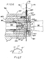
- punch 80A when punch 80A is moved towards sleeve member 84A by the reciprocation assembly, punch surface 98A forces web 72 against cutter ring 162A and cuts free a circular bottom blank B. Reciprocation assembly continues to move punch 80A forward until the bottom blank is clamped against the abutment surface 86A.
- the abutment surface 86A is not provided with projections for the purpose of creating score lines in the outer peripheral portion of the blank. Furthermore, the angular position of the cams 118 relative to that of the eccentric 130 of the prior art machine is changed so that the draw 82A begins to push the central portion of the blank into the opening 88A while the outer peripheral portion of the blank remains firmly (immovably) clamped between the punch 80A and the abutment surface, as shown in Fig. 6. That causes the non-clamped central portion of the blank to be radially stretched.
- the punch 80A begins to be retracted to progressively reduce the clamping force, allowing the outer peripheral portion to be pulled into the opening 88A.
- the retraction is performed at a rate just sufficient to prevent the paper from ripping.
- the radial gap between the outer cylindrical surface of the draw 82A and the cylindrical surface of the opening 88A is slightly less than the thickness of the blank passing through the gap so that the paper becomes compressed.
- the outer peripheral portion is bent to a right angle relative to the center part of the blank, and is also compressed.
- the paperboard web 72 could be pre-moistened in order to facilitate the stretching.
Landscapes
- Making Paper Articles (AREA)
Applications Claiming Priority (2)
| Application Number | Priority Date | Filing Date | Title |
|---|---|---|---|
| US09/251,355 US6135936A (en) | 1999-02-17 | 1999-02-17 | Paper cup bottoms and method and apparatus for forming same |
| US251355 | 1999-02-17 |
Publications (2)
| Publication Number | Publication Date |
|---|---|
| EP1029656A2 true EP1029656A2 (fr) | 2000-08-23 |
| EP1029656A3 EP1029656A3 (fr) | 2001-03-14 |
Family
ID=22951600
Family Applications (1)
| Application Number | Title | Priority Date | Filing Date |
|---|---|---|---|
| EP00102271A Withdrawn EP1029656A3 (fr) | 1999-02-17 | 2000-02-16 | Fonds de gobelet en papier et procédé et appareil pour leur fabrication |
Country Status (4)
| Country | Link |
|---|---|
| US (2) | US6135936A (fr) |
| EP (1) | EP1029656A3 (fr) |
| JP (1) | JP2000238150A (fr) |
| CA (1) | CA2299120C (fr) |
Cited By (1)
| Publication number | Priority date | Publication date | Assignee | Title |
|---|---|---|---|---|
| US9783359B2 (en) | 2005-09-08 | 2017-10-10 | Seda S.P.A. | Double-walled cup |
Families Citing this family (26)
| Publication number | Priority date | Publication date | Assignee | Title |
|---|---|---|---|---|
| US6135936A (en) * | 1999-02-17 | 2000-10-24 | Fort James Corporation | Paper cup bottoms and method and apparatus for forming same |
| DE60102661T2 (de) | 2001-01-30 | 2004-08-19 | Seda S.P.A. | Pappbehälter für Getränke und Verfahren hierfür |
| US20040006950A1 (en) * | 2002-07-09 | 2004-01-15 | Knoerzer Anthony Robert | Flexible-round stand-up pouch |
| US7699216B2 (en) | 2003-11-26 | 2010-04-20 | Solo Cup Operating Corporation | Two-piece insulated cup |
| US20050184136A1 (en) * | 2004-02-24 | 2005-08-25 | Fort James Corporation | Adjustable portion cup with invertible sidewall panel |
| US20060009338A1 (en) * | 2004-07-12 | 2006-01-12 | Kirkpatrick John T | Apparatus and process for cups having a metallized/holographic PET film exterior |
| US7281649B2 (en) * | 2004-11-19 | 2007-10-16 | Solo Cup Operating Corporation | Bottom seal for container |
| BRPI0601188B1 (pt) | 2005-04-15 | 2018-06-26 | Seda S.P.A. | Recipiente isolado; método de fabricar o mesmo e aparelho para a fabricação |
| DE602005005493T3 (de) | 2005-11-11 | 2014-04-24 | Seda S.P.A. | Isolierbecher |
| EP1785265A1 (fr) | 2005-11-14 | 2007-05-16 | SEDA S.p.A. | Dispositif pour former un élément en saillie d'empilage sur une parois d'un récipient et récipient avec un tel élément |
| CN100462221C (zh) * | 2006-06-14 | 2009-02-18 | 彭来静 | 纸杯成型机的方形纸杯底部滚花装置 |
| DE202006018406U1 (de) | 2006-12-05 | 2008-04-10 | Seda S.P.A. | Verpackung |
| DE102007039843A1 (de) * | 2007-08-16 | 2009-02-19 | Q-Bag Packaging Machinery Gmbh & Co. Kg | Vorrichtung und Verfahren zum Anbringen eines Bodens |
| US20090276096A1 (en) * | 2008-05-02 | 2009-11-05 | Carrier Corporation | Device and method for controlling a display using a virtual display buffer |
| JP2013082109A (ja) | 2011-10-07 | 2013-05-09 | Toyo Seikan Kaisha Ltd | しわ発生の少ない紙成形体とその製造方法 |
| JP6101000B2 (ja) | 2012-01-30 | 2017-03-22 | 東洋製罐株式会社 | 紙成形体を製造する方法及びその装置 |
| WO2017146698A1 (fr) | 2016-02-24 | 2017-08-31 | Bemis Company, Inc. | Poche multicouche à couche thermorétractable |
| US11578462B2 (en) | 2018-04-27 | 2023-02-14 | Westrock Mwv, Llc | Anti-blocking high barrier paperboard structures |
| JP2021522420A (ja) | 2018-04-27 | 2021-08-30 | ウエストロック・エム・ダブリュー・ヴイ・エルエルシー | ヒートシール可能な板紙構造体および関連の板紙による容器 |
| MX2020011180A (es) | 2018-04-30 | 2020-11-12 | Westrock Mwv Llc | Recipiente de carton recubierto, metodo de manufactura de un recipiente de carton recubierto y aparato formador de fondo de vaso. |
| CN108943837B (zh) * | 2018-07-20 | 2024-06-18 | 浙江森创包装有限公司 | 方形纸容器的底纸模切装置 |
| CN112109377B (zh) * | 2019-12-24 | 2022-08-26 | 河北龙大包装制品有限公司 | 双层耐热型纸杯加工装置 |
| CN111730904B (zh) * | 2020-06-28 | 2021-11-09 | 安庆市芊芊纸业有限公司 | 一种纸杯杯底成型机 |
| CN112026252A (zh) * | 2020-09-15 | 2020-12-04 | 浙江瑞大机械有限公司 | 纸杯杯底冲裁成型输送一体机构 |
| CN112721311A (zh) * | 2020-12-30 | 2021-04-30 | 温州拓浦诺机械有限公司 | 纸杯成型机的双滚花轮式异形杯杯底滚花机构 |
| CN112895587B (zh) * | 2021-01-04 | 2022-01-14 | 合肥恒鑫生活科技股份有限公司 | 一种高速纸杯成型装置及其制备工艺 |
Family Cites Families (14)
| Publication number | Priority date | Publication date | Assignee | Title |
|---|---|---|---|---|
| US3118351A (en) * | 1964-01-21 | Comcal container of paper | ||
| DE604448C (de) * | 1930-05-03 | 1934-10-22 | Angel Internat Corp | Maschine zur Herstellung von konischen Papierhohlbehaeltern |
| DE2422080A1 (de) * | 1974-05-07 | 1975-11-20 | Impraegnieranstalt Ag Zofingen | Einsteckdeckel fuer einen behaelter |
| US4191322A (en) * | 1975-11-10 | 1980-03-04 | Phillips Petroleum Company | Pleated closure construction |
| US4349400A (en) * | 1977-05-10 | 1982-09-14 | Maryland Cup Corporation | Method for manufacturing two-piece containers from filled thermoplastic sheet material |
| US4721500A (en) * | 1982-04-13 | 1988-01-26 | James River-Dixie Northern, Inc. | Method of forming a rigid paper-board container |
| US4599123A (en) * | 1982-09-02 | 1986-07-08 | Esselte Pac Aktiebolag | Method and apparatus for manufacturing a container having an inner end closure |
| SE454083B (sv) * | 1983-05-19 | 1988-03-28 | Esseltepack Ab | Forfarande och anordning for framstellning av en forpackning med belgbotten |
| US4865506A (en) * | 1987-08-24 | 1989-09-12 | Stolle Corporation | Apparatus for reforming an end shell |
| JPH04282235A (ja) * | 1991-03-11 | 1992-10-07 | Sadami Ito | 絞り成形装置 |
| US5324249A (en) * | 1992-08-28 | 1994-06-28 | Paper Machinery Corporation | Cup making machine |
| US5531235A (en) * | 1992-09-28 | 1996-07-02 | Hassenboehler, Jr.; Charles B. | Cigarette filter micropleated web and method of manufacture |
| US5624367A (en) * | 1994-09-15 | 1997-04-29 | Paper Machinery Corporation | Bottom blank maker workstation for a cup making machine |
| US6135936A (en) * | 1999-02-17 | 2000-10-24 | Fort James Corporation | Paper cup bottoms and method and apparatus for forming same |
-
1999
- 1999-02-17 US US09/251,355 patent/US6135936A/en not_active Expired - Fee Related
-
2000
- 2000-02-16 EP EP00102271A patent/EP1029656A3/fr not_active Withdrawn
- 2000-02-17 JP JP2000040088A patent/JP2000238150A/ja active Pending
- 2000-02-17 CA CA002299120A patent/CA2299120C/fr not_active Expired - Fee Related
- 2000-10-02 US US09/676,950 patent/US6264100B1/en not_active Expired - Fee Related
Cited By (1)
| Publication number | Priority date | Publication date | Assignee | Title |
|---|---|---|---|---|
| US9783359B2 (en) | 2005-09-08 | 2017-10-10 | Seda S.P.A. | Double-walled cup |
Also Published As
| Publication number | Publication date |
|---|---|
| US6135936A (en) | 2000-10-24 |
| US6264100B1 (en) | 2001-07-24 |
| CA2299120C (fr) | 2008-01-22 |
| JP2000238150A (ja) | 2000-09-05 |
| EP1029656A3 (fr) | 2001-03-14 |
| CA2299120A1 (fr) | 2000-08-17 |
Similar Documents
| Publication | Publication Date | Title |
|---|---|---|
| US6135936A (en) | Paper cup bottoms and method and apparatus for forming same | |
| US4838064A (en) | Apparatus for flanging and swaging a cylindrical can body on both ends | |
| DE2353209C2 (de) | Verfahren zum Herstellen eines einstückigen, einendig offenen Behälters aus Metall, insbesondere Metalldose | |
| DE60201504T2 (de) | Verfahren und vorrichtung zum einhalsen der öffnung eines behälters | |
| US20020148272A1 (en) | Method and apparatus for forming deep-drawn articles | |
| DE3940235A1 (de) | Verfahren zum aufbau einer wulstanordnung fuer kraftwagenreifen, baueinrichtung hierfuer sowie vorrichtung zur bildung einer unter-baugruppe aus fueller/wulstring | |
| DE69110766T2 (de) | Verpackung. | |
| JPS5921691B2 (ja) | 衝撃プレス | |
| US20100242567A1 (en) | Method and apparatus for producing untrimmed container bodies | |
| US4033241A (en) | Apparatus for manufacturing cardboard tubes | |
| US2333997A (en) | Cathode forming machine | |
| US7066702B2 (en) | Aerosol can ends | |
| US2889866A (en) | Apparatus for forming tubular sleeves | |
| US3380272A (en) | Apparatus for forming foil containers | |
| US11484930B2 (en) | Punching tool comprising a punch and a die | |
| DE2804642C2 (de) | Vorrichtung zur Herstellung und Überführung von Behälterböden in eine Boden-Einbring-Station | |
| JP3736676B2 (ja) | 連続加工装置 | |
| WO1997049510A1 (fr) | Realisation de bords annulaires de couvercles sans production de dechets ronds | |
| WO1994005508A1 (fr) | Procede et appareil de production de dossiers | |
| DE3126947C2 (de) | Vorrichtung zum Formen des Randes eines Behälters | |
| JP7645012B1 (ja) | 中空ロールバーオブジェクト切断機構及び方法 | |
| JPH11198909A (ja) | 可動部材を備える包装機 | |
| DE69326273T2 (de) | Verfahren und Vorrichtung zur Herstellung von Kennzeichenschildern, insbesondere reflektierenden Schildern | |
| EP1838473B1 (fr) | Procede et dispositif pour produire des sections tubulaires | |
| RU2209701C2 (ru) | Способ раздачи тонкостенных трубчатых заготовок |
Legal Events
| Date | Code | Title | Description |
|---|---|---|---|
| PUAI | Public reference made under article 153(3) epc to a published international application that has entered the european phase |
Free format text: ORIGINAL CODE: 0009012 |
|
| AK | Designated contracting states |
Kind code of ref document: A2 Designated state(s): AT BE CH CY DE DK ES FI FR GB GR IE IT LI LU MC NL PT SE |
|
| AX | Request for extension of the european patent |
Free format text: AL;LT;LV;MK;RO;SI |
|
| RIN1 | Information on inventor provided before grant (corrected) |
Inventor name: BROWN, DAVID C. Inventor name: CURCIO, ANTHONY N. Inventor name: GRISHCHENKO, GRIGORY |
|
| PUAL | Search report despatched |
Free format text: ORIGINAL CODE: 0009013 |
|
| AK | Designated contracting states |
Kind code of ref document: A3 Designated state(s): AT BE CH CY DE DK ES FI FR GB GR IE IT LI LU MC NL PT SE |
|
| AX | Request for extension of the european patent |
Free format text: AL;LT;LV;MK;RO;SI |
|
| 17P | Request for examination filed |
Effective date: 20010821 |
|
| AKX | Designation fees paid |
Free format text: AT BE CH CY DE DK ES FI FR GB GR IE IT LI LU MC NL PT SE |
|
| STAA | Information on the status of an ep patent application or granted ep patent |
Free format text: STATUS: THE APPLICATION IS DEEMED TO BE WITHDRAWN |
|
| 18D | Application deemed to be withdrawn |
Effective date: 20050901 |
|
| RIN1 | Information on inventor provided before grant (corrected) |
Inventor name: GRISHCHENKO, GRIGORY Inventor name: CURCIO, ANTHONY N. Inventor name: BROWN, DAVID C. |