EP1033497A2 - Nagelpistole und Stossdämpfer dafür, zum Bremsen der Stosskolben - Google Patents
Nagelpistole und Stossdämpfer dafür, zum Bremsen der Stosskolben Download PDFInfo
- Publication number
- EP1033497A2 EP1033497A2 EP00250080A EP00250080A EP1033497A2 EP 1033497 A2 EP1033497 A2 EP 1033497A2 EP 00250080 A EP00250080 A EP 00250080A EP 00250080 A EP00250080 A EP 00250080A EP 1033497 A2 EP1033497 A2 EP 1033497A2
- Authority
- EP
- European Patent Office
- Prior art keywords
- bumper
- impact
- impact piston
- driver
- piston
- Prior art date
- Legal status (The legal status is an assumption and is not a legal conclusion. Google has not performed a legal analysis and makes no representation as to the accuracy of the status listed.)
- Granted
Links
- 239000011800 void material Substances 0.000 claims abstract description 14
- 238000010521 absorption reaction Methods 0.000 description 5
- 239000012141 concentrate Substances 0.000 description 1
- 230000002787 reinforcement Effects 0.000 description 1
- 238000009751 slip forming Methods 0.000 description 1
Images


Classifications
-
- F—MECHANICAL ENGINEERING; LIGHTING; HEATING; WEAPONS; BLASTING
- F15—FLUID-PRESSURE ACTUATORS; HYDRAULICS OR PNEUMATICS IN GENERAL
- F15B—SYSTEMS ACTING BY MEANS OF FLUIDS IN GENERAL; FLUID-PRESSURE ACTUATORS, e.g. SERVOMOTORS; DETAILS OF FLUID-PRESSURE SYSTEMS, NOT OTHERWISE PROVIDED FOR
- F15B15/00—Fluid-actuated devices for displacing a member from one position to another; Gearing associated therewith
- F15B15/20—Other details, e.g. assembly with regulating devices
- F15B15/22—Other details, e.g. assembly with regulating devices for accelerating or decelerating the stroke
- F15B15/226—Other details, e.g. assembly with regulating devices for accelerating or decelerating the stroke having elastic elements, e.g. springs, rubber pads
-
- B—PERFORMING OPERATIONS; TRANSPORTING
- B25—HAND TOOLS; PORTABLE POWER-DRIVEN TOOLS; MANIPULATORS
- B25C—HAND-HELD NAILING OR STAPLING TOOLS; MANUALLY OPERATED PORTABLE STAPLING TOOLS
- B25C1/00—Hand-held nailing tools; Nail feeding devices
- B25C1/04—Hand-held nailing tools; Nail feeding devices operated by fluid pressure, e.g. by air pressure
- B25C1/047—Mechanical details
-
- F—MECHANICAL ENGINEERING; LIGHTING; HEATING; WEAPONS; BLASTING
- F15—FLUID-PRESSURE ACTUATORS; HYDRAULICS OR PNEUMATICS IN GENERAL
- F15B—SYSTEMS ACTING BY MEANS OF FLUIDS IN GENERAL; FLUID-PRESSURE ACTUATORS, e.g. SERVOMOTORS; DETAILS OF FLUID-PRESSURE SYSTEMS, NOT OTHERWISE PROVIDED FOR
- F15B15/00—Fluid-actuated devices for displacing a member from one position to another; Gearing associated therewith
- F15B15/20—Other details, e.g. assembly with regulating devices
- F15B15/22—Other details, e.g. assembly with regulating devices for accelerating or decelerating the stroke
- F15B15/222—Other details, e.g. assembly with regulating devices for accelerating or decelerating the stroke having a piston with a piston extension or piston recess which throttles the main fluid outlet as the piston approaches its end position
Definitions
- the present invention relates to a nailer and a bumper provided therein for braking a motion of an impact piston.
- a bumper provided within a nailer is disposed at a lower portion of an impact cylinder, which slidably houses an impact piston. Said bumper is used for braking the impact piston by receiving a bottom surface of the actuated impact piston when the nailer is driving in a fastener such as a nail.
- the term "nailer” means of an apparatus that includes so called a “tacker” for driving a staple in as well as an apparatus for driving in a various types of nails.
- a volume of the bumper is desirably large.
- an outer diameter of the bumper is greater than that of a diameter of the impact piston, an upper surface of the bumper 10 is cracked due to the impact made when it is striked, as shown in Fig. 5(a), and the bumper is damaged.
- the bumper 10 may be also small. Therefore, a central hole of the bumper for inserting the driver of the nailer is deformed in accordance with the configuration of the driver, further, a reinforcement to thin parts of the deformed shape caused by the deformation is required.
- a transverse section of the driver 11 is formed in a rectangular shape so that a transverse section of a central hole 12 of the bumper 10 for inserting the driver 11, as shown in Fig. 5(b), is formed in an elliptic configuration to surround the driver 11.
- a bumper including an upper part having a transverse section of an annulus ring, an inner surface of the annulus ring having a size to form a void between the inner surface and an outer surface of the upper portion of a driver, and a top surface for receiving an impact piston, the top surface having an outer diameter of the same size as that of the impact piston.
- a bumper including a transverse section of an annulus ring, an inner surface of the annulus ring having a size to form a void between the inner surface and an outer surface of the upper portion of a driver, and a longitudinal length longer than at least the amount of longitudinal shrinkage of the upper part of the bumper by an impact on collision of an impact piston against the upper part.
- a nailer equipped with a bumper including an upper part having a transverse section of an annulus ring, an inner surface of the annulus ring having a size to form a void between the inner surface and an outer surface of the upper portion of a driver, and a top surface for receiving an impact piston, the top surface having an outer diameter of the same size as that of the impact piston.
- a nailer equipped with a bumper including an upper part formed in a shape having a transverse section of an annulus ring, an inner surface of the annulus ring having a size to form a void between the inner surface and an outer surface of the upper portion of a driver, and a longitudinal length longer than at least an amount of longitudinal shrinkage of an upper part of the bumper by an impact on collision of an impact piston against the upper part of the bumper.
- Fig. 1 is a side view illustrating of an embodiment of a nailer according to the present invention, a part of which is shown in section.
- Fig. 2(a) is a side view of a driver joined together with an impact piston of the nailer in Fig. 1
- Fig. 2(b) is a sectional view of the driver viewed from the a-a line of Fig. 2(a).
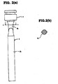
- Fig. 3(a) is a top view of the bumper in Fig. 1
- Fig. 3(b) is a sectional view of the bumper viewed from the b-b line of Fig. 3(a).
- Fig. 4(a) and Fig. 4(b) are sectional views illustrating a respective state of before and after an impact is made to the bumper in Fig. 1.
- Fig. 4(a) illustrates the state before the impact is made to the bumper
- Fig. 4(b) illustrates the state after the impact is made to the bumper.
- Fig. 5(a) is a vertical sectional view of a conventional bumper, an impact piston and a driver
- Fig. 5(b) is a transverse sectional view of the bumper and the driver of Fig. 5(a).
- a reference numeral 1 designates an impact cylinder, a numeral 2 an impact piston, and a numeral 3 a bumper.
- a nose portion 4 is disposed downward of the impact cylinder 1.
- the nose portion 4 is constituted in such a manner that a staple (not shown) can be fed therein by a feeding mechanism.
- the impact piston 2 is slidably stored within the impact cylinder 1, driven by compressed air that is supplied to an upper portion of the impact cylinder 1, and further strikes the staple inside the nose portion 4. Then, a bottom surface of the impact piston 2, which is driven by the compressed air, is received and stopped by the bumper 3.
- the bumper 3 then absorbs an impact when caused by the collision of the piston 2 with the bumper 3.
- a driver 6 is integrally joined together with the impact piston 2 on the lowermost surface thereof.
- a transverse section of an upper portion 6a of the driver 6 is formed in a circular shape, and a transverse section of a lower portion 6b of the driver 6 is formed in a rectangular.
- the bumper 3 is constituted of an elastic member such as a rubber.
- a plane view of the bumper 3 and a transverse section of a center hole 7 for inserting the driver 6, as shown in Fig. 3(a), are shaped in circular respectively.
- the bumper 3 is mounted at a lower portion of a body A .
- the bumper 3 has an upper small diameter portion 3a, an intermediate portion 3b and a lower large diameter portion 3c, which are continuously formed in a longitudinal configuration.
- the upper small diameter portion 3a is formed perpendicular to a bottom surface of the bumper 3, and an outer diameter of which is approximately similar in size to that of the impact piston 2. Further, in the case where the driver 6 is inserted into the upper small diameter portion 3a of the central hole 7, as shown in Fig. 4(a), a void 8 is slightly formed between the inner surface of the central hole 7 and an outer surface of the driver 6. A height H of the upper small diameter portion 3a is formed in such a manner so that the height H is greater than that of a quantity of deflection h due to the impact applied by the impact piston 2.
- the lower large diameter portion 3c is perpendicular to the bottom surface of the bumper 3, and an outer diameter of which is formed larger than that of the upper small diameter portion 3a. Further, the central hole 7 is formed so that a downward side is large and an upward side is small at the lower large diameter portion 3c.
- the intermediate portion 3b is formed so that an outer diameter of a downward side of which is large and an outer diameter of an upward side of which is small in order to connect the upper small diameter portion 3a and the lower large diameter portion 3c.
- the transverse section of the bumper 3 has an annulus ring configuration and the transverse section of the central hole 7 is a circle so that stress is not concentrated at one point when the impact is made on the bumper 3. Therefore, those shapes protect the bumper 3 from being partially deformed.
- the bumper 3 has no unnecessary portion, and thus enables downsizing thereof without losing the sufficient performance and the durability. Further, a load is equally distributed on the bumper 3, causing an even deformation of the bumper 3. And also such a configuration allows an easier designing of the bumper 3.
- the upper small diameter portion 3a of the bumper 3 is deformed by the impact made by the impact piston 2.
- the deformation works inward towards the void 8, generating a strong braking force in such a manner as to stop the driver 6.
- the braking force by a friction is produced between the inner wall of the upper small diameter portion 3a and the intermediate portion 3b of the bumper 3 and the outer surface of the driver 6.
- the height of the bumper 3 may be suppressed, as the deformation that occurs in upward and downward direction thereof is not the only means to absorb the energy due to the impact. Further, performance of absorption may be designed by adjusting the void 8 between the bumper 3 and the driver 6.
- the height of the upper small diameter portion 3a is formed to be greater than the amount of deformation when the impact is made so that a compressed portion cannot escape outward. Therefore, the amount of deformation is small, causing the bumper 3 difficult to be damaged, furthermore, the durability of the bumper 3 is improved.
- the bumper 3 is provided with the sufficient performance of absorption together with the durability for protecting a damage caused by an excess of the deformation. Therefore, a tool with a large output energy can be obtained even the diameter of the impact piston 2 is small according to the use of the high pressurized compressed air.
- the staple is used as a fastener in this embodiment, however, a nail in a needle like configuration may be also used.
Landscapes
- Engineering & Computer Science (AREA)
- Physics & Mathematics (AREA)
- Fluid Mechanics (AREA)
- Mechanical Engineering (AREA)
- General Engineering & Computer Science (AREA)
- Portable Nailing Machines And Staplers (AREA)
Applications Claiming Priority (2)
| Application Number | Priority Date | Filing Date | Title |
|---|---|---|---|
| JP05763299A JP3622193B2 (ja) | 1999-03-04 | 1999-03-04 | 釘打機、タッカ等のバンパ |
| JP5763299 | 1999-03-04 |
Publications (3)
| Publication Number | Publication Date |
|---|---|
| EP1033497A2 true EP1033497A2 (de) | 2000-09-06 |
| EP1033497A3 EP1033497A3 (de) | 2003-02-05 |
| EP1033497B1 EP1033497B1 (de) | 2005-06-22 |
Family
ID=13061282
Family Applications (1)
| Application Number | Title | Priority Date | Filing Date |
|---|---|---|---|
| EP00250080A Expired - Lifetime EP1033497B1 (de) | 1999-03-04 | 2000-03-02 | Nagelpistole und Stossdämpfer dafür, zum Bremsen der Stosskolben |
Country Status (4)
| Country | Link |
|---|---|
| US (1) | US6318239B1 (de) |
| EP (1) | EP1033497B1 (de) |
| JP (1) | JP3622193B2 (de) |
| DE (1) | DE60020898T2 (de) |
Cited By (1)
| Publication number | Priority date | Publication date | Assignee | Title |
|---|---|---|---|---|
| EP2269780A1 (de) * | 2009-06-29 | 2011-01-05 | Max Co., Ltd. | Antriebswerkzeug und Dämpfer für das Antriebswerkzeug |
Families Citing this family (10)
| Publication number | Priority date | Publication date | Assignee | Title |
|---|---|---|---|---|
| JP3818234B2 (ja) * | 2002-07-19 | 2006-09-06 | 日立工機株式会社 | 釘打機 |
| US20050001007A1 (en) * | 2003-05-29 | 2005-01-06 | Butzen Robert W. | Pneumatic nailer |
| JP2005271086A (ja) * | 2004-03-22 | 2005-10-06 | Hitachi Koki Co Ltd | 打込機 |
| USD560108S1 (en) | 2005-07-19 | 2008-01-22 | Milwaukee Electric Tool Corporation | Power tool, such as a nailer |
| US7975777B2 (en) * | 2008-12-19 | 2011-07-12 | Robert Bosch Gmbh | Cellular foam bumper for nailer |
| DE202009008323U1 (de) | 2009-06-17 | 2009-09-03 | Lehmann, Titus | Schlagzylinder |
| US20150159436A1 (en) * | 2013-12-06 | 2015-06-11 | Natalino Giraldi | Ground hole forming device |
| JP2017213634A (ja) * | 2016-05-31 | 2017-12-07 | 日立工機株式会社 | 打込機 |
| US10800022B2 (en) * | 2017-02-09 | 2020-10-13 | Illinois Tool Works Inc. | Powered-fastener-driving tool including a driver blade having a varying cross-section |
| JP7073197B2 (ja) * | 2018-06-04 | 2022-05-23 | 株式会社マキタ | 打ち込み工具 |
Family Cites Families (16)
| Publication number | Priority date | Publication date | Assignee | Title |
|---|---|---|---|---|
| US3035268A (en) * | 1959-10-05 | 1962-05-22 | Modernair Corp | Pneumatically-operated fastener driving machine |
| DE1238409B (de) * | 1961-02-11 | 1967-04-06 | Haubold Dieter | Mit Pressluft betriebenes Handgeraet zum Eintreiben von Befestigungsmitteln, wie Klammern, Naegeln u. dgl. |
| DE1478836A1 (de) * | 1965-06-18 | 1969-01-23 | Behrens Friedrich Joh | Eintreibgeraet zum Einschlagen von Befestigungsmitteln |
| US3504840A (en) * | 1968-02-28 | 1970-04-07 | Fastener Corp | Fastener driving tool |
| DE6915710U (de) * | 1969-04-19 | 1969-09-18 | Reich Maschf Gmbh Karl | Geraet zum einschlagen naegeln oder dergleichen. |
| US3605559A (en) * | 1969-08-18 | 1971-09-20 | Jurgen Korth | Pneumatically actuated stapling device |
| US3871566A (en) * | 1972-07-25 | 1975-03-18 | Behrens Friedrich Joh | Fastener driver tools |
| US3776445A (en) * | 1972-08-24 | 1973-12-04 | Omark Industries Inc | Pneumatic fastener driving device |
| US4188858A (en) * | 1978-05-11 | 1980-02-19 | Signode Corporation | Bumper deterioration warning system for fastener driving tools |
| US4549344A (en) * | 1980-11-19 | 1985-10-29 | Signode Corporation | Method of driving fasteners with a bumperless pneumatic gun |
| FR2608493B1 (fr) * | 1986-12-23 | 1994-09-02 | Prospection & Inventions | Appareil de scellement a tir indirect |
| DE3924620A1 (de) * | 1989-07-26 | 1991-01-31 | Hilti Ag | Pulverkraftbetriebenes bolzensetzgeraet |
| DE9305760U1 (de) * | 1993-04-16 | 1993-06-17 | Joh. Friedrich Behrens AG, 2070 Ahrensburg | Auslösesicherung an einem Eintreibgerät für Befestigungsmittel |
| JPH07156078A (ja) * | 1993-12-03 | 1995-06-20 | Kanematsu Nnk Corp | 固着具打撃工具 |
| JP3137227B2 (ja) * | 1995-06-09 | 2001-02-19 | マックス株式会社 | 釘打機の安全機構 |
| EP0747175B1 (de) * | 1995-06-09 | 2003-08-27 | Max Co., Ltd. | Auslasssystem für eine Maschine zum Eintreiben von Nägeln |
-
1999
- 1999-03-04 JP JP05763299A patent/JP3622193B2/ja not_active Expired - Lifetime
-
2000
- 2000-03-02 EP EP00250080A patent/EP1033497B1/de not_active Expired - Lifetime
- 2000-03-02 DE DE60020898T patent/DE60020898T2/de not_active Expired - Lifetime
- 2000-03-06 US US09/519,844 patent/US6318239B1/en not_active Expired - Lifetime
Non-Patent Citations (1)
| Title |
|---|
| None |
Cited By (3)
| Publication number | Priority date | Publication date | Assignee | Title |
|---|---|---|---|---|
| EP2269780A1 (de) * | 2009-06-29 | 2011-01-05 | Max Co., Ltd. | Antriebswerkzeug und Dämpfer für das Antriebswerkzeug |
| US8544561B2 (en) | 2009-06-29 | 2013-10-01 | Max Co., Ltd. | Driving tool and bumper of driving tool |
| TWI549788B (zh) * | 2009-06-29 | 2016-09-21 | 美克司股份有限公司 | 打擊工具及打擊工具用緩衝器 |
Also Published As
| Publication number | Publication date |
|---|---|
| JP3622193B2 (ja) | 2005-02-23 |
| EP1033497A3 (de) | 2003-02-05 |
| EP1033497B1 (de) | 2005-06-22 |
| DE60020898D1 (de) | 2005-07-28 |
| US6318239B1 (en) | 2001-11-20 |
| DE60020898T2 (de) | 2006-05-18 |
| JP2000246666A (ja) | 2000-09-12 |
Similar Documents
| Publication | Publication Date | Title |
|---|---|---|
| CN101934515B (zh) | 击打工具及击打工具用缓冲器 | |
| CN101500760B (zh) | 动力工具及其冲击机构 | |
| US5860580A (en) | Piston retention device for combustion-powered tools | |
| US6318239B1 (en) | Nailer and bumper provided therein for braking impact piston | |
| JP2004050358A (ja) | 釘打機 | |
| US6779698B2 (en) | Abrasion-resistant bumper for a nail-driving tool | |
| JP2876982B2 (ja) | 空気圧式衝撃工具の緩衝装置 | |
| JPS6033637B2 (ja) | 電気ハンマ | |
| JPH09300238A (ja) | 打込機のドライバブレード | |
| JP2576575Y2 (ja) | 釘打機の緩衝装置 | |
| JPS5917586Y2 (ja) | 打撃工具におけるバンパの破壊防止装置 | |
| JP3915956B2 (ja) | 打込機 | |
| JPH0617882U (ja) | 固着具打撃工具 | |
| JP3401948B2 (ja) | 打込機 | |
| JP2001162557A (ja) | 打込機 | |
| JP4174727B2 (ja) | 釘打機 | |
| KR200263380Y1 (ko) | 건설시공공구 | |
| JPH07672U (ja) | 固着具打撃工具 | |
| JPH0234485Y2 (de) | ||
| JPH0675677U (ja) | 打込機 | |
| JP2003117851A5 (de) | ||
| JP2007069345A (ja) | 空気式打込機 | |
| JPH0586483U (ja) | 工具保持装置 | |
| JP2000334679A (ja) | 打込機 |
Legal Events
| Date | Code | Title | Description |
|---|---|---|---|
| PUAI | Public reference made under article 153(3) epc to a published international application that has entered the european phase |
Free format text: ORIGINAL CODE: 0009012 |
|
| AK | Designated contracting states |
Kind code of ref document: A2 Designated state(s): AT BE CH CY DE DK ES FI FR GB GR IE IT LI LU MC NL PT SE |
|
| AX | Request for extension of the european patent |
Free format text: AL;LT;LV;MK;RO;SI |
|
| PUAL | Search report despatched |
Free format text: ORIGINAL CODE: 0009013 |
|
| AK | Designated contracting states |
Designated state(s): AT BE CH CY DE DK ES FI FR GB GR IE IT LI LU MC NL PT SE |
|
| AX | Request for extension of the european patent |
Extension state: AL LT LV MK RO SI |
|
| 17P | Request for examination filed |
Effective date: 20030320 |
|
| 17Q | First examination report despatched |
Effective date: 20030903 |
|
| AKX | Designation fees paid |
Designated state(s): DE FR GB |
|
| GRAP | Despatch of communication of intention to grant a patent |
Free format text: ORIGINAL CODE: EPIDOSNIGR1 |
|
| GRAS | Grant fee paid |
Free format text: ORIGINAL CODE: EPIDOSNIGR3 |
|
| GRAA | (expected) grant |
Free format text: ORIGINAL CODE: 0009210 |
|
| AK | Designated contracting states |
Kind code of ref document: B1 Designated state(s): DE FR GB |
|
| REG | Reference to a national code |
Ref country code: GB Ref legal event code: FG4D |
|
| REF | Corresponds to: |
Ref document number: 60020898 Country of ref document: DE Date of ref document: 20050728 Kind code of ref document: P |
|
| ET | Fr: translation filed | ||
| PLBE | No opposition filed within time limit |
Free format text: ORIGINAL CODE: 0009261 |
|
| STAA | Information on the status of an ep patent application or granted ep patent |
Free format text: STATUS: NO OPPOSITION FILED WITHIN TIME LIMIT |
|
| 26N | No opposition filed |
Effective date: 20060323 |
|
| PGFP | Annual fee paid to national office [announced via postgrant information from national office to epo] |
Ref country code: GB Payment date: 20090325 Year of fee payment: 10 |
|
| PGFP | Annual fee paid to national office [announced via postgrant information from national office to epo] |
Ref country code: FR Payment date: 20090324 Year of fee payment: 10 |
|
| GBPC | Gb: european patent ceased through non-payment of renewal fee |
Effective date: 20100302 |
|
| REG | Reference to a national code |
Ref country code: FR Ref legal event code: ST Effective date: 20101130 |
|
| PG25 | Lapsed in a contracting state [announced via postgrant information from national office to epo] |
Ref country code: FR Free format text: LAPSE BECAUSE OF NON-PAYMENT OF DUE FEES Effective date: 20100331 |
|
| PG25 | Lapsed in a contracting state [announced via postgrant information from national office to epo] |
Ref country code: GB Free format text: LAPSE BECAUSE OF NON-PAYMENT OF DUE FEES Effective date: 20100302 |
|
| PGFP | Annual fee paid to national office [announced via postgrant information from national office to epo] |
Ref country code: DE Payment date: 20190219 Year of fee payment: 20 |
|
| REG | Reference to a national code |
Ref country code: DE Ref legal event code: R071 Ref document number: 60020898 Country of ref document: DE |