EP1036614B1 - Eintauchausguss zur Verwendung beim Stranggiessen - Google Patents
Eintauchausguss zur Verwendung beim Stranggiessen Download PDFInfo
- Publication number
- EP1036614B1 EP1036614B1 EP00105363A EP00105363A EP1036614B1 EP 1036614 B1 EP1036614 B1 EP 1036614B1 EP 00105363 A EP00105363 A EP 00105363A EP 00105363 A EP00105363 A EP 00105363A EP 1036614 B1 EP1036614 B1 EP 1036614B1
- Authority
- EP
- European Patent Office
- Prior art keywords
- nozzle
- spinel
- refractory material
- submerged entry
- less
- Prior art date
- Legal status (The legal status is an assumption and is not a legal conclusion. Google has not performed a legal analysis and makes no representation as to the accuracy of the status listed.)
- Revoked
Links
- 238000009749 continuous casting Methods 0.000 title claims abstract description 14
- 229910000831 Steel Inorganic materials 0.000 claims abstract description 76
- 239000010959 steel Substances 0.000 claims abstract description 76
- 239000011819 refractory material Substances 0.000 claims abstract description 63
- 229910052596 spinel Inorganic materials 0.000 claims abstract description 55
- 239000011029 spinel Substances 0.000 claims abstract description 55
- OKTJSMMVPCPJKN-UHFFFAOYSA-N Carbon Chemical compound [C] OKTJSMMVPCPJKN-UHFFFAOYSA-N 0.000 claims abstract description 38
- 239000010439 graphite Substances 0.000 claims abstract description 29
- 229910002804 graphite Inorganic materials 0.000 claims abstract description 29
- 238000000034 method Methods 0.000 claims abstract description 17
- 239000000843 powder Substances 0.000 claims abstract description 11
- 229910003112 MgO-Al2O3 Inorganic materials 0.000 claims abstract description 10
- 239000000463 material Substances 0.000 claims description 32
- 239000002245 particle Substances 0.000 claims description 16
- 239000002994 raw material Substances 0.000 claims description 10
- 230000015572 biosynthetic process Effects 0.000 claims description 5
- PNEYBMLMFCGWSK-UHFFFAOYSA-N aluminium oxide Inorganic materials [O-2].[O-2].[O-2].[Al+3].[Al+3] PNEYBMLMFCGWSK-UHFFFAOYSA-N 0.000 claims description 2
- 229910052593 corundum Inorganic materials 0.000 claims description 2
- 229910001845 yogo sapphire Inorganic materials 0.000 claims description 2
- 238000002844 melting Methods 0.000 abstract description 35
- 230000008018 melting Effects 0.000 abstract description 35
- 239000003795 chemical substances by application Substances 0.000 abstract description 23
- 238000005266 casting Methods 0.000 abstract description 14
- 238000004519 manufacturing process Methods 0.000 abstract description 12
- 229910052760 oxygen Inorganic materials 0.000 abstract description 11
- 230000035939 shock Effects 0.000 abstract description 11
- QVGXLLKOCUKJST-UHFFFAOYSA-N atomic oxygen Chemical compound [O] QVGXLLKOCUKJST-UHFFFAOYSA-N 0.000 abstract description 10
- 239000001301 oxygen Substances 0.000 abstract description 10
- 229910001220 stainless steel Inorganic materials 0.000 abstract description 10
- 239000010935 stainless steel Substances 0.000 abstract description 10
- 230000000052 comparative effect Effects 0.000 description 19
- VYPSYNLAJGMNEJ-UHFFFAOYSA-N Silicium dioxide Chemical compound O=[Si]=O VYPSYNLAJGMNEJ-UHFFFAOYSA-N 0.000 description 14
- 239000000203 mixture Substances 0.000 description 13
- MCMNRKCIXSYSNV-UHFFFAOYSA-N Zirconium dioxide Chemical compound O=[Zr]=O MCMNRKCIXSYSNV-UHFFFAOYSA-N 0.000 description 12
- 239000011572 manganese Substances 0.000 description 12
- 229910052799 carbon Inorganic materials 0.000 description 11
- 238000012360 testing method Methods 0.000 description 9
- 229910052681 coesite Inorganic materials 0.000 description 8
- 229910052906 cristobalite Inorganic materials 0.000 description 8
- 239000000377 silicon dioxide Substances 0.000 description 8
- 229910052682 stishovite Inorganic materials 0.000 description 8
- 239000000126 substance Substances 0.000 description 8
- 229910052905 tridymite Inorganic materials 0.000 description 8
- 239000007788 liquid Substances 0.000 description 5
- 239000002893 slag Substances 0.000 description 5
- -1 Y2O3 Chemical compound 0.000 description 4
- 239000011230 binding agent Substances 0.000 description 4
- 238000006243 chemical reaction Methods 0.000 description 4
- UQSXHKLRYXJYBZ-UHFFFAOYSA-N iron oxide Inorganic materials [Fe]=O UQSXHKLRYXJYBZ-UHFFFAOYSA-N 0.000 description 4
- 238000002474 experimental method Methods 0.000 description 3
- 229910052500 inorganic mineral Inorganic materials 0.000 description 3
- XEEYBQQBJWHFJM-UHFFFAOYSA-N iron Substances [Fe] XEEYBQQBJWHFJM-UHFFFAOYSA-N 0.000 description 3
- 239000011707 mineral Substances 0.000 description 3
- 238000002156 mixing Methods 0.000 description 3
- 238000011160 research Methods 0.000 description 3
- 238000009694 cold isostatic pressing Methods 0.000 description 2
- QDOXWKRWXJOMAK-UHFFFAOYSA-N dichromium trioxide Chemical compound O=[Cr]O[Cr]=O QDOXWKRWXJOMAK-UHFFFAOYSA-N 0.000 description 2
- 238000001035 drying Methods 0.000 description 2
- 238000011049 filling Methods 0.000 description 2
- 238000010304 firing Methods 0.000 description 2
- AMWRITDGCCNYAT-UHFFFAOYSA-L hydroxy(oxo)manganese;manganese Chemical compound [Mn].O[Mn]=O.O[Mn]=O AMWRITDGCCNYAT-UHFFFAOYSA-L 0.000 description 2
- 229910052742 iron Inorganic materials 0.000 description 2
- 229910052748 manganese Inorganic materials 0.000 description 2
- 150000004767 nitrides Chemical class 0.000 description 2
- 238000005245 sintering Methods 0.000 description 2
- 229910016384 Al4C3 Inorganic materials 0.000 description 1
- QYEXBYZXHDUPRC-UHFFFAOYSA-N B#[Ti]#B Chemical compound B#[Ti]#B QYEXBYZXHDUPRC-UHFFFAOYSA-N 0.000 description 1
- 229910019918 CrB2 Inorganic materials 0.000 description 1
- 229910005331 FeSi2 Inorganic materials 0.000 description 1
- 229910000655 Killed steel Inorganic materials 0.000 description 1
- KKCBUQHMOMHUOY-UHFFFAOYSA-N Na2O Inorganic materials [O-2].[Na+].[Na+] KKCBUQHMOMHUOY-UHFFFAOYSA-N 0.000 description 1
- 206010039509 Scab Diseases 0.000 description 1
- 229910052581 Si3N4 Inorganic materials 0.000 description 1
- 229910033181 TiB2 Inorganic materials 0.000 description 1
- GWEVSGVZZGPLCZ-UHFFFAOYSA-N Titan oxide Chemical compound O=[Ti]=O GWEVSGVZZGPLCZ-UHFFFAOYSA-N 0.000 description 1
- 229910021541 Vanadium(III) oxide Inorganic materials 0.000 description 1
- 229910007948 ZrB2 Inorganic materials 0.000 description 1
- 229910006249 ZrSi Inorganic materials 0.000 description 1
- 230000002159 abnormal effect Effects 0.000 description 1
- 229910052782 aluminium Inorganic materials 0.000 description 1
- 239000012300 argon atmosphere Substances 0.000 description 1
- VWZIXVXBCBBRGP-UHFFFAOYSA-N boron;zirconium Chemical compound B#[Zr]#B VWZIXVXBCBBRGP-UHFFFAOYSA-N 0.000 description 1
- CETPSERCERDGAM-UHFFFAOYSA-N ceric oxide Chemical compound O=[Ce]=O CETPSERCERDGAM-UHFFFAOYSA-N 0.000 description 1
- 229910000422 cerium(IV) oxide Inorganic materials 0.000 description 1
- 238000007796 conventional method Methods 0.000 description 1
- 238000005336 cracking Methods 0.000 description 1
- 239000013078 crystal Substances 0.000 description 1
- 230000003247 decreasing effect Effects 0.000 description 1
- 230000007547 defect Effects 0.000 description 1
- 238000009826 distribution Methods 0.000 description 1
- 230000000694 effects Effects 0.000 description 1
- 230000001747 exhibiting effect Effects 0.000 description 1
- 150000004676 glycans Chemical class 0.000 description 1
- 229910000765 intermetallic Inorganic materials 0.000 description 1
- 238000004898 kneading Methods 0.000 description 1
- 229910052751 metal Inorganic materials 0.000 description 1
- 239000002184 metal Substances 0.000 description 1
- 150000001247 metal acetylides Chemical class 0.000 description 1
- 229910052750 molybdenum Inorganic materials 0.000 description 1
- HFLAMWCKUFHSAZ-UHFFFAOYSA-N niobium dioxide Inorganic materials O=[Nb]=O HFLAMWCKUFHSAZ-UHFFFAOYSA-N 0.000 description 1
- 230000003647 oxidation Effects 0.000 description 1
- 238000007254 oxidation reaction Methods 0.000 description 1
- 230000000149 penetrating effect Effects 0.000 description 1
- 239000005011 phenolic resin Substances 0.000 description 1
- 229920001282 polysaccharide Polymers 0.000 description 1
- 239000005017 polysaccharide Substances 0.000 description 1
- NOTVAPJNGZMVSD-UHFFFAOYSA-N potassium monoxide Inorganic materials [K]O[K] NOTVAPJNGZMVSD-UHFFFAOYSA-N 0.000 description 1
- 229910001404 rare earth metal oxide Inorganic materials 0.000 description 1
- 230000009257 reactivity Effects 0.000 description 1
- 229910052710 silicon Inorganic materials 0.000 description 1
- 238000004901 spalling Methods 0.000 description 1
- 230000035882 stress Effects 0.000 description 1
- 230000008646 thermal stress Effects 0.000 description 1
- OGIDPMRJRNCKJF-UHFFFAOYSA-N titanium oxide Inorganic materials [Ti]=O OGIDPMRJRNCKJF-UHFFFAOYSA-N 0.000 description 1
- 229910003470 tongbaite Inorganic materials 0.000 description 1
- 229910052721 tungsten Inorganic materials 0.000 description 1
Images


Classifications
-
- B—PERFORMING OPERATIONS; TRANSPORTING
- B22—CASTING; POWDER METALLURGY
- B22D—CASTING OF METALS; CASTING OF OTHER SUBSTANCES BY THE SAME PROCESSES OR DEVICES
- B22D41/00—Casting melt-holding vessels, e.g. ladles, tundishes, cups or the like
- B22D41/50—Pouring-nozzles
- B22D41/52—Manufacturing or repairing thereof
- B22D41/54—Manufacturing or repairing thereof characterised by the materials used therefor
Definitions
- This invention relates to a submerged entry nozzle for use in a continuous casting process, in particular to a submerged entry nozzle for use in a continuous casting process suitable for casting various types of steel such as high concentration oxygen-containing steel, high concentration Mn-containing steel, Ca-treated steel, stainless steel.
- a submerged entry nozzle is usually employed to introduce molten steel from a tundish into a mold.
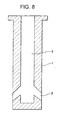
- Fig. 8 is a cross sectional view schematically showing a typical structure of a submerged entry nozzle made according to the prior art.
- a vertically arranged elongated internal hole 2 and a plurality of discharge openings 3 arranged exactly perpendicular or generally perpendicular to the internal hole 2.
- the molten steel from the tundish is at first introduced into the internal hole 2 and then caused to flow in different directions through the discharge openings 3, thereby allowing the molten steel to be injected uniformly into a mold.
- one of the most widely used submerged entry nozzles has been an Al 2 O 3 -SiO 2 -C (hereinafter, simply referred to as "AG") submerged entry nozzle.
- AG Al 2 O 3 -SiO 2 -C
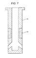
- Fig. 7 is another cross sectional view schematically indicating pattern for arranging different materials in a conventional AG submerged entry nozzle.
- a mold powder line portion 14 of the nozzle is formed by a ZrO 2 -C material, with other portions, i.e., the main body portions 11 of the submerged entry nozzle being formed of an AG material.
- improved submerged entry nozzles whose internal surface is formed by a carbonless refractory material containing not over 5 wt% of SiO 2 but containing 90 wt% or more of one or more substances selected from the group consisting of Al 2 O 3 , MgO, ZrO 2 (Japanese Patent Laid-Open No. 3-243258).
- the inventors of the present invention have carried out a research on the mechanism of melting loss in an AG submerged entry nozzle under conditions where it is used for casting various types of steel such as high concentration oxygen-containing steel, high concentration Mn-containing steel, Ca-treated steel, stainless steel.
- steel such as high concentration oxygen-containing steel, high concentration Mn-containing steel, Ca-treated steel, stainless steel.
- the mechanism which the inventors have found will be discussed in the following.
- the working surface will become just Al 2 O 3 -SiO 2 oxides.
- MnO-FeO type inclusion substances will impinge and adhere to the working surface.
- CaO-Al 2 O 3 type inclusion substances will impinge and adhere to the working surface.
- a refractory material containing 90 wt% or more of Al 2 O 3 , ZrO 2 or particularly MgO has a large coefficient of thermal expansion. Further, in the vicinity of the discharge openings of the submerged entry nozzle, there are many working surfaces that are subject to thermal shock, resulting in complex shapes where stress is likely to collect.
- an object of the present invention is. to provide an improved submerged entry nozzle which has sufficient melting loss resistance and sufficient thermal shock resistance, so that it is suitable for use in casting various types of steel such as high concentration oxygen-containing steel, high concentration Mn-containing steel, Ca-treated steel, stainless steel. Further, the submerged entry nozzle of the present invention may also be manufactured under improved conditions at reduced production costs.
- a submerged entry nozzle for continuous casting is an improved submerged entry nozzle usually for use in introducing a molten steel from a tundish into a mold, characterized in that at least part of the portions surrounding the nozzle discharge openings, preferably most portions thereof, are made of a graphite-containing refractory material containing 5 to 35 wt% graphite, 65 wt% or more of a spinel (MgO-Al 2 O 3 ), with a total content of other components being 10 wt% or less; at least part of the internal wall material within the nozzle, preferably most portions thereof, being made of a graphite-less refractory material containing 90 wt% or more of a spinel, with a total content of other components being 10 wt% or less.
- a graphite-containing refractory material containing 5 to 35 wt% graphite, 65 wt% or more of a spinel (MgO-Al 2 O 3 ), with a
- the submerged entry nozzle for continuous casting according to the present invention is characterized in that the content of MgO in the spinel is 20 to 45 wt%, and the content of Al 2 O 3 in the spinel is 55 to 80 wt%.
- the submerged entry nozzle for continuous casting according to the present invention is characterized in that it employs a refractory raw material which is comprised of a spinel material with a particle size distribution such that particles of 1 mm or less are contained in an amount of 95 wt% or more, and particles of 0.5 mm or less are contained in an amount of 70 wt% or more.
- the submerged entry nozzle for continuous casting according to the present invention is characterized in that the nozzle internal hole portion containing the spinel has a thickness of 1 to 10 mm.
- the submerged entry nozzle for continuous casting according to the present invention is characterized in that it has an integrally formed structure in which the portions surrounding the discharge openings, the nozzle internal hole portion and the nozzle main body portion, or the portions in powder line with the above portions have been formed simultaneously into an integral structure during a formation process.
- the nozzle of the present invention will be described in more detail.
- the nozzle of the present invention is characterized in that at least part of the surrounding portions around the nozzle discharge openings, preferably most portions thereof, are made of a graphite-containing refractory material containing 5 to 35 wt% of a graphite, 65 wt% or more of a spinel (MgO-Al 2 O 3 ), with a total content of other components being 10 wt% or less (including cases not containing said other components); at least one part of the internal wall material within the nozzle, preferably most portions thereof, is made of a graphite-less refractory material, but containing 90 wt% or more of a spinel, with a total content of other components being 10 wt% or less (including cases not containing said other components).
- a graphite-containing refractory material containing 5 to 35 wt% of a graphite, 65 wt% or more of a spinel (MgO-Al 2 O 3 ), with a total content of other components
- MnO, FeO or CaO in the spinel has an extremely large thermo-dynamic activity, and the reactions shown in the above equations (2) to (5) are not likely to occur, hence making it difficult for the MnO, FeO or CaO in a molten steel to penetrate into the spinel.
- the spinel when used as a main component of an aggregate of a refractory material forming a working surface of the nozzle, even if the nozzle is employed to cast various types of steel such as high concentration oxygen-containing steel, high concentration Mn-containing steel, Ca-treated steel and stainless steel, melting loss is not likely to occur in the nozzle.
- One of the most important points with respect to the nozzle of the present invention is how to control the mineral composition of a refractory material. Namely, even if several components may be similar to one another, when they have different mineral structures (different crystal structures), they will have different reactivities when reacting with a molten steel. As a result, the melting loss of one component will differ greatly from that of another. For example, if a comparison is made between spinel and a material formed by mixing together MgO and Al 2 O 3 , it will be found that although they have similar chemical compositions, it is spinel that has a remarkably higher melting loss resistance.
- spinel (MgO-Al 2 O 3 ) represents a spinel having a theoretical composition with a molecular formula of MgO ⁇ Al 2 O 3 , and/or a spinel having a non-theoretical composition rich in MgO, and/or a spinel having a non-theoretical composition rich in Al 2 O 3 (however, those rich in MgO or in Al 2 O 3 do not exist in a free state).
- the spinel which servers as a main component for forming the above refractory material, as other components it is allowed to include in the refractory material one or more of the following substances, in view of conditions for manufacturing the nozzle and conditions for casting a steel using the nozzle, thereby allowing the thus formed refractory material to have improved sinterability, improved filling formability and improved resistance against atmospheric oxidation.
- the above-mentioned other components may be oxides such as CaO, BaO, BeO, MgO, ZrO 2 , Al 2 O 3 , SiO 2 , Cr 2 O 3 , NbO 2 , V 2 O 3 , K 2 O, Na 2 O, a titanium oxide, iron oxide, manganese oxide and rare earth oxides (such as Y 2 O 3 , CeO 2 ), carbides such as SiC, Al 4 C 3 , TiC, ZrC, NbC, VC, Cr 3 C 2 , B 4 C, nitrides such as Si 3 N 4 , AlN, BN, borides such as ZrB 2 , TiB 2 , VB 2 , CrB 2 , W 2 B 5 , oxidated nitrides such as ALON, SIALON, metal or intermetallic compounds such as Al, Si, Fe, Mo, Mn, W, ZrSi, FeSi 2 .
- oxides such as CaO, BaO, BeO
- the mixing amount of any of the above substances be 10 wt% or less. If the mixing amount is larger than 10 wt%, melting loss resistance of the nozzle will be deteriorated.
- the nozzle since at least part of the adjacent portions surrounding the nozzle discharge openings, preferably most portions thereof, contain 5 to 35 wt% graphite, the nozzle has good thermal shock resistance, thus preventing possible cracks. Moreover, the concentration of carbon dissolved from the nozzle into the molten steel is so small that it can be ignored.
- the thermal shock resistance of the nozzle will be poor, causing cracking during use.
- the content of the graphite is 35 wt% or more, there will occur a reaction represented by the above equation (1), causing the graphite to dissolve into the molten steel, hence bringing about a heavy damage to the nozzle.
- the molten steel will have increased carbon concentration due to carbon dissolving carbon from the nozzle.
- such increased carbon concentration in the molten steel is not desirable.
- the concentration of carbon dissolved from the nozzle into the molten steel is so small that it can be ignored.
- the refractory material forming the nozzle may be considered to be a graphite-less refractory material.
- the nozzle for continuous casting according to the present invention is characterized in that the content of MgO in the spinel is 20 to 45 wt%, and the content of Al 2 O 3 in the spinel is 55 to 80 wt%.
- the content of MgO in the spinel is less than 20 wt% or larger than 45 wt%, or if the content of Al 2 O 3 in the spinel is less than 55 wt% or larger than 80 wt%, the weight ratio of the spinel phase in a theoretical structure will become too small, causing the spinel to lose its melting loss resistance, thus it is not desirable.
- the nozzle of the present invention is characterized in that it employs a refractory raw material which is comprised of a spinel material whose particle size is distributed such that particles having a size of 1 mm or less are contained in an amount of 95 wt% or more, and particles having a size of 0.5 mm or less are contained in an amount of 70 wt% or more.
- the amount of spinel material having a particle size of more than 1 mm is larger than 5 wt%, the particle size of the raw material will be too large.
- the refractory structure of the nozzle when in use particularly the refractory structure surrounding the discharge openings through which the molten steel flow is violent, will become fragile and thus cause the refractory particles to drop off.
- the amount of spinel material having a particle size of less than 0.5 mm is less than 70 wt%, a desired formability when forming the nozzle will be deteriorated, hence making it difficult to obtain a nozzle having a desired shape.
- the expression "the particle size of spinel refractory material” is used to mean the particle size of the spinel material itself which is used as a refractory raw material and/or the particle size of a refractory raw material for forming the spinel material.
- the nozzle of the present invention is characterized in that the nozzle internal hole portion containing the spinel has a thickness of 1 to 10 mm.
- the above thickness is less than 1 mm, the strength of the internal hole portion will be too weak, making it difficult to endure the impact caused by the flowing of a molten steel, producing an undesired possibility that the internal hole portion will peel off from the nozzle main body.
- the above thickness is larger than 10 mm, the thermal expansion difference between the internal hole portion and the refractory material forming the nozzle main body will be too large. As a result, there is a fear that cracks will develop in the internal hole portion (its thermal shock resistance will be deteriorated), thus it is not desirable.
- the nozzle of the present invention is characterized in that it has an integrally formed structure in which different but adjacent portions have been formed simultaneously into an integral structure during a formation process.
- a nozzle has a structure obtained by forming an internal hole portion and adjacent portions surrounding the discharge openings (all containing the spinel material) independently of the nozzle main body and then inserting these portions into the nozzle main body, it is likely that an undesired slot will occur between the internal hole portion and the above surrounding portions, hence causing these portions to peel off from the nozzle main body.
- a binder such as a phenol resin or a polysaccharide is added and mixed (kneaded) into the refractory raw material for forming the nozzle internal hole portion and the portions surrounding the discharge openings, and also into the refractory raw material for forming the nozzle main body. subsequently, the kneaded mixtures are filled into predetermined positions in a mold. After that, CIP (Cold Isostatic Pressing) or a similar method is used to pressure form the nozzle, followed by drying, firing or non-firing, to thereby complete the manufacturing process.
- CIP Cold Isostatic Pressing
- a refractory material for forming the nozzle main body of the present invention an AG refractory material which has long been used conventionally may be used.
- a conventionally used composition for example, 30 to 90 wt% Al 2 O 3 , 0 to 35 wt% SiO 2 and 10 to 35 wt% C may be used.
- a conventional ZrO 2 -C refractory material in which ZrO 2 is 60 to 90 wt% and C is 10 to 30 wt% may be used.
- a conventional method for forming discharge openings in the nozzle of the present invention a conventional method for forming discharge openings in a conventional AG submerged entry nozzle may be used. Namely, according to the method a related above, a nozzle is first formed, then a drying treatment is carried out. Subsequently, a lathe is used to cut openings at predetermined positions of the nozzle. The adjacent portions surrounding the discharge openings of the nozzle contain 5 wt% graphite, and have good workability, so that it is easy to form the discharge openings in the nozzle with the use of such a method.
- the nozzle of the present invention may be manufactured in a simplified process involving fewer steps with reduced cost, so that such a nozzle is suitable for mass production on an industrial scale.
- Fig. 1 is a sectional view (showing material arrangement pattern 1) schematically indicating a nozzle made according to a first embodiment of the present invention.
- reference numeral 11 represents a main body portion formed by an AG refractory material
- reference numeral 12 represents an internal hole portion made of a graphite-less refractory material which contains 90 wt% or more of a spinel, with the remainder being 10 wt% or less.
- Reference numeral 13 represents portions surrounding the discharge openings, which is formed by a graphite-containing refractory material containing 5 to 35 wt% of a graphite, 65 wt% or more of a spinel (MgO-Al 2 O 3 ), with a total content of other components being 10 wt% or less.
- Reference numeral 14 represents a powder line portion formed by a ZrO 2 -C refractory material.
- Fig. 2 is a sectional view (showing material arrangement pattern 2) schematically indicating a nozzle made according to a second embodiment of the present invention.
- reference numeral 11 represents a main body portion formed by an AG refractory material
- reference numeral 12 represents an internal hole portion made of a graphite-less refractory material which does not contain a graphite, but contains 90 wt% or more of a spinel, with the remainder being 10 wt% or less.
- Reference numeral 13 represents portions surrounding the discharge openings, which is formed by a graphite-containing refractory material containing 5 to 35 wt% of a graphite, 65 wt% or more of a spinel (MgO-Al 2 O 3 ), with a total content of other components being 10 wt% or less.
- Reference numeral 14 represents a powder line portion formed by a ZrO 2 -C refractory material.
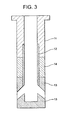
- Fig. 3 is a sectional view (showing material arrangement pattern 3) schematically indicating a nozzle made according to a third embodiment of the present invention.
- reference numeral 11 represents a main body portion formed by an AG refractory material
- reference numeral 12 represents an internal hole portion made of a graphite-less refractory material which contains 90 wt% or more of a spinel, with the remainder being 10 wt% or less.
- Reference numeral 13 represents surrounding portions around the discharge openings, which is formed by a graphite-containing refractory material containing 5 to 35 wt% graphite, 65 wt% or more of a spinel (MgO-Al 2 O 3 ), with a total content of other components being 10 wt% or less.
- Reference numeral 14 represents a powder line portion formed by a ZrO 2 -C refractory material.
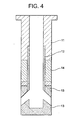
- Fig. 4 is a sectional view (showing material arrangement pattern 4) schematically indicating a nozzle made according to a fourth embodiment of the present invention.
- reference numeral 11 represents a main body portion formed by an AG refractory material
- reference numeral 12 represents an internal hole portion made of a graphite-less refractory material which contains 90 wt% or more of a spinel, with the remainder being 10 wt% or less.
- Reference numeral 13 represents portions surrounding the discharge openings, which is formed by a graphite-containing refractory material containing 5 to 35 wt% graphite, 65 wt% or more of a spinel (MgO-Al 2 O 3 ), with a total content of other components being 10 wt% or less.
- Reference numeral 14 represents a powder line portion formed by a ZrO 2 -C refractory material.
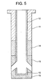
- Fig. 5 is a sectional view (showing material arrangement pattern 5) schematically indicating a nozzle made according to a fifth embodiment of the present invention.
- reference numeral 11 represents a main body portion formed by an AG refractory material
- reference numeral 12 represents an internal hole portion made of a graphite-less refractory material which contains 90 wt% or more of a spinel, with the remainder being 10 wt% or less.
- Reference numeral 13 represents portions surrounding the discharge openings, which is formed by a graphite-containing refractory material containing 5 to 35 wt% graphite, 65 wt% or more of a spinel (MgO-Al 2 O 3 ), with a total content of other components being 10 wt% or less.
- Reference numeral 14 represents a powder line portion formed by a ZrO 2 -C refractory material.
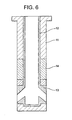
- Fig. 6 is a sectional view schematically indicating a material arrangement pattern which is different from the material arrangement patterns 1 to 5 shown in the first to fifth embodiments of the present invention.
- reference numeral 11 represents a main body portion formed by an AG refractory material.
- a refractory material used to form the internal hole portion is different from the refractory material used to form the surrounding portions around the discharge openings
- a refractory material used to form the internal hole portion 12 is different from the refractory material used to form the portions 13 surrounding the discharge openings.
- the internal hole portion 12 and the portions 13 surrounding the discharge openings are formed by the same refractory material which does not contain graphite but contains 90 wt% or more of a spinel, with the remainder being 10 wt% or less.
- reference numeral 14 represents a powder line portion formed by a ZrO 2 -C refractory material.
- the raw materials of the mineral phase shown in Table 1 were blended together in accordance with the composition percentages shown in Table 1, thereby obtaining mixtures (samples) for use as raw materials, which are inventive samples 1 to 8 for use in the present invention and comparative samples 1 to 6 for comparison.
- a high concentration oxygen-containing steel was melted in a high frequency furnace under an argon atmosphere and kept at 1580°C. Then, the samples each having a diameter of 40 mm and a height of 230 mm were dipped in the molten steel, and the furnace was rotated at a velocity of 100 rpm for 60 minutes. After that, the diameter of each sample was measured to investigate its melting loss amount, thereby evaluating the melting loss resistance of each sample, based on a melting loss index with a melting loss amount of AG refractory material (which is a sample for comparison) being 1. As a result, it was found that a ⁇ smaller melting loss index will produce better melting loss resistance.
- Examples 1 to 3 of the present invention as shown in Table 2, the inventive samples 1, 6 and 7 were used to form the internal hole portions, while the inventive samples 4, 8 were used to form the portions surrounding the discharge openings, thereby obtaining the nozzle of the present invention having the material arrangement patterns shown in Figs. 1, 2 and 5.
- inventive samples 1 and 7 were used to form both the internal hole portion and the portions surrounding the discharge openings, thereby obtaining the nozzle of the comparative examples having the material arrangement pattern shown in Fig. 6.
- Comparative Examples 3 and 4 as shown in Table 2, comparative samples 3 and 5 were used to form both the internal hole portion and the portions surrounding the discharge openings, thereby obtaining the nozzle of the comparative example having the material arrangement pattern shown in Fig. 6.
- the nozzles of the present invention and the nozzles of the comparative examples were measured to investigate their thermal shock resistance with the use of the following testing method.
- each nozzle was made as a submerged entry nozzle having a size suitable for actual use. Then, the nozzles were dipped in 300 tons molten steel for 3 minutes without having preheated. Subsequently, the nozzles were taken out of the molten steel and air cooled, so as to confirm whether any cracks had generated in the nozzles. Further, the nozzles were cut at the middle portions thereof to confirm whether there were any internal cracks.
- each of the comparative nozzles developed cracks, while none of the inventive nozzles produced such cracks, thereby proving that the nozzles made according to the present invention have an extremely excellent thermal shock resistance.
- Example 1 shown in Fig. 2 As the nozzle according to the present invention, that made in Example 1 shown in Fig. 2 was used. As the nozzle made according to the comparative example, the conventional AG submerged entry nozzle shown in Fig. 7 was used.
- both the nozzles of the present invention and the conventional AG submerged entry nozzles were used in a test for casting Al-killed steel.
- the nozzle of the present invention it is possible to extend the usable life of the nozzle, improve the quality of a steel product made by using the nozzle, and ensure a stabilized casting process operation.
Landscapes
- Engineering & Computer Science (AREA)
- Manufacturing & Machinery (AREA)
- Mechanical Engineering (AREA)
- Compositions Of Oxide Ceramics (AREA)
- Casting Support Devices, Ladles, And Melt Control Thereby (AREA)
- Continuous Casting (AREA)
- Organic Low-Molecular-Weight Compounds And Preparation Thereof (AREA)
Claims (5)
- Taucheintrittsdüse zur Verwendung in einem kontinuierlichen Giessverfahren, die verwendet wird zur Einführung von geschmolzenem Stahl aus einer Giesswanne in eine Form, worin mindestens ein Teil der Bereiche, die die Austrittsöffnungen in der Düse umgeben, aus einem graphithaltigen feuerfesten Material, das 5-35 Gew.% Graphit, 65 Gew.% oder mehr eines Spinells (MgO-Al2O3) und einen Gesamtgehalt anderer Komponenten von 10 Gew.% oder weniger enthält, hergestellt ist, und worin zumindest ein Teil des inneren Wandmaterials innerhalb der Düse aus einem graphitfreien feuerfesten Material hergestellt ist, das 90 Gew.% oder mehr eines Spinells enthält, und dessen Gesamtgehalt an anderen Komponenten 10 Gew.% oder weniger beträgt.
- Taucheintrittsdüse gemäss Anspruch 1, worin der Gehalt an MgO in dem Spinell 20-45 Gew.% beträgt, und der Gehalt an Al2O3 in dem Spinell ist 55-80 Gew.%.
- Taucheintrittsdüse gemäss Anspruch 1 oder 2, worin die Düse ein feuerfestes Rohmaterial verwendet, das ein Spinellmaterial umfasst, dessen Teilchengrösse so verteilt ist, dass Teilchen mit einer Grösse von 1 mm oder weniger in einer Menge von 95 Gew.% oder mehr enthalten sind, und Teilchen mit einer Grösse von 0,5 mm oder weniger in einer Menge von 70 Gew.% oder mehr enthalten sind.
- Taucheintrittsdüse gemäss Anspruch 1, worin der innere Düsenlochbereich, der den Spinell enthält, eine Dicke von 1-10 mm aufweist.
- Taucheintrittsdüse gemäss Anspruch 1, worin die Düse eine integral ausgebildete Struktur aufweist, in der die Bereiche, die die Austrittsöffnungen umgeben, der innere Düsenlochbereich und der Düsenhauptkörperbereich oder Bereiche in Pulverlinie (powder line) mit dem obigen Bereich während der Ausbildungsverfahrens gleichzeitig zu einer integralen Struktur ausgebildet werden.
Applications Claiming Priority (2)
| Application Number | Priority Date | Filing Date | Title |
|---|---|---|---|
| JP07459999A JP3421917B2 (ja) | 1999-03-18 | 1999-03-18 | 連続鋳造用浸漬ノズル |
| JP7459999 | 1999-03-18 |
Publications (2)
| Publication Number | Publication Date |
|---|---|
| EP1036614A1 EP1036614A1 (de) | 2000-09-20 |
| EP1036614B1 true EP1036614B1 (de) | 2003-06-25 |
Family
ID=13551791
Family Applications (1)
| Application Number | Title | Priority Date | Filing Date |
|---|---|---|---|
| EP00105363A Revoked EP1036614B1 (de) | 1999-03-18 | 2000-03-17 | Eintauchausguss zur Verwendung beim Stranggiessen |
Country Status (6)
| Country | Link |
|---|---|
| US (1) | US6279790B1 (de) |
| EP (1) | EP1036614B1 (de) |
| JP (1) | JP3421917B2 (de) |
| AT (1) | ATE243593T1 (de) |
| AU (1) | AU733878B2 (de) |
| DE (1) | DE60003479T2 (de) |
Families Citing this family (25)
| Publication number | Priority date | Publication date | Assignee | Title |
|---|---|---|---|---|
| JPS6444262A (en) * | 1987-08-11 | 1989-02-16 | Kobe Steel Ltd | Separation of molten iron and molten slag |
| KR20030045970A (ko) * | 2001-12-03 | 2003-06-12 | 주식회사 포스코 | 타이타늄 함유 스테인레스강의 연속주조용 턴디쉬 노즐 |
| WO2003064079A1 (fr) * | 2002-01-28 | 2003-08-07 | Jfe Steel Corporation | Busette immergee pour une coulee continue de l'acier et procede de coulee continue de l'acier |
| US7363959B2 (en) | 2006-01-17 | 2008-04-29 | Nucor Corporation | Submerged entry nozzle with installable parts |
| US20060243760A1 (en) * | 2005-04-27 | 2006-11-02 | Mcintosh James L | Submerged entry nozzle |
| US7757747B2 (en) | 2005-04-27 | 2010-07-20 | Nucor Corporation | Submerged entry nozzle |
| US7926550B2 (en) * | 2007-01-19 | 2011-04-19 | Nucor Corporation | Casting delivery nozzle with insert |
| US7926549B2 (en) * | 2007-01-19 | 2011-04-19 | Nucor Corporation | Delivery nozzle with more uniform flow and method of continuous casting by use thereof |
| JP5134516B2 (ja) * | 2008-12-04 | 2013-01-30 | 黒崎播磨株式会社 | 連続鋳造用ノズル |
| US8047264B2 (en) * | 2009-03-13 | 2011-11-01 | Nucor Corporation | Casting delivery nozzle |
| JP5291662B2 (ja) * | 2010-04-28 | 2013-09-18 | 黒崎播磨株式会社 | 耐火物、その耐火物を使用した連続鋳造用ノズル及びその連続鋳造用ノズルの製造方法、並びにその連続鋳造用ノズルを使用した連続鋳造方法 |
| EP2441740A4 (de) * | 2010-05-07 | 2012-12-05 | Krosakiharima Corp | Feuerfester baustoff, nahtlose gussdüse mit dem feuerfesten baustoff, verfahren zur herstellung der nahtlosen gussdüse und kontinuierliches gussverfahren mit der nahtlosen gussdüse |
| JP2012210647A (ja) * | 2011-03-31 | 2012-11-01 | Sumitomo Metal Ind Ltd | 連続鋳造用浸漬ノズルおよびこれを用いた連続鋳造方法 |
| WO2013190594A1 (ja) * | 2012-06-20 | 2013-12-27 | 新日鐵住金株式会社 | 連続鋳造用浸漬ノズルおよびこれを用いた連続鋳造方法 |
| JP5768773B2 (ja) * | 2012-07-02 | 2015-08-26 | 新日鐵住金株式会社 | 浸漬ノズルを用いた連続鋳造方法 |
| JP5757275B2 (ja) * | 2012-07-17 | 2015-07-29 | 新日鐵住金株式会社 | 浸漬ノズルを用いた連続鋳造方法 |
| CN105983684B (zh) * | 2015-03-05 | 2018-10-02 | 宝山钢铁股份有限公司 | 一种含低碳内孔体的浸入式水口 |
| JP6582606B2 (ja) * | 2015-06-24 | 2019-10-02 | 品川リフラクトリーズ株式会社 | スピネル−マグネシア−カーボン質煉瓦 |
| JP6112176B1 (ja) * | 2015-10-28 | 2017-04-12 | 品川リフラクトリーズ株式会社 | 浸漬ノズル |
| CN105965005A (zh) * | 2016-07-07 | 2016-09-28 | 宜兴市耐火材料有限公司 | 一种长水口砖 |
| JP6734539B2 (ja) * | 2016-10-11 | 2020-08-05 | 品川リフラクトリーズ株式会社 | 超高マンガン鋼の連続鋳造方法 |
| CN111036891A (zh) * | 2019-11-29 | 2020-04-21 | 浙江科宇金属材料有限公司 | 垂直铸造用浇管 |
| CN114292117A (zh) * | 2022-01-27 | 2022-04-08 | 无锡市南方耐材有限公司 | 中包高性能钢用连铸三大件及其制备方法 |
| EP4561771A1 (de) | 2022-07-28 | 2025-06-04 | Tata Steel IJmuiden B.V. | Düse mit untergetauchtem eintritt |
| TW202529912A (zh) | 2024-01-24 | 2025-08-01 | 奧地利商瑞法克托瑞智產股份有限公司 | 浸沒式入口噴嘴及浸沒式入口噴嘴的製造方法 |
Family Cites Families (6)
| Publication number | Priority date | Publication date | Assignee | Title |
|---|---|---|---|---|
| JPS573764A (en) * | 1980-06-10 | 1982-01-09 | Kurosaki Refractories Co | Nozzle for steel continuous casting |
| JP3219095B2 (ja) | 1990-02-20 | 2001-10-15 | 日新製鋼株式会社 | 連続鋳造用ノズル |
| US5370370A (en) | 1993-02-19 | 1994-12-06 | Vesuvius Crucible Company | Liner for submerged entry nozzle |
| US5681499A (en) | 1994-06-15 | 1997-10-28 | Vesuvius Crucible Company | Method and compositions for making refractory shapes having dense, carbon free surfaces and shapes made therefrom |
| US5908577A (en) | 1996-08-26 | 1999-06-01 | Shinagawa Refractories Co., Ltd. | Nozzle for continuous casting |
| JP3137939B2 (ja) | 1998-01-14 | 2001-02-26 | 品川白煉瓦株式会社 | 鋼の連続鋳造用浸漬ノズル |
-
1999
- 1999-03-18 JP JP07459999A patent/JP3421917B2/ja not_active Expired - Fee Related
-
2000
- 2000-03-16 US US09/527,575 patent/US6279790B1/en not_active Expired - Fee Related
- 2000-03-17 AU AU22387/00A patent/AU733878B2/en not_active Ceased
- 2000-03-17 DE DE60003479T patent/DE60003479T2/de not_active Expired - Fee Related
- 2000-03-17 EP EP00105363A patent/EP1036614B1/de not_active Revoked
- 2000-03-17 AT AT00105363T patent/ATE243593T1/de not_active IP Right Cessation
Also Published As
| Publication number | Publication date |
|---|---|
| US6279790B1 (en) | 2001-08-28 |
| EP1036614A1 (de) | 2000-09-20 |
| AU733878B2 (en) | 2001-05-31 |
| ATE243593T1 (de) | 2003-07-15 |
| JP2000263200A (ja) | 2000-09-26 |
| DE60003479D1 (de) | 2003-07-31 |
| AU2238700A (en) | 2000-10-12 |
| JP3421917B2 (ja) | 2003-06-30 |
| DE60003479T2 (de) | 2004-05-06 |
Similar Documents
| Publication | Publication Date | Title |
|---|---|---|
| EP1036614B1 (de) | Eintauchausguss zur Verwendung beim Stranggiessen | |
| JP6172226B2 (ja) | 連続鋳造用浸漬ノズル | |
| JP3213699B2 (ja) | 鋼の連続鋳造用ノズル | |
| US6637629B2 (en) | Immersion nozzle | |
| KR100971260B1 (ko) | 연속 주조 노즐 | |
| JP3137939B2 (ja) | 鋼の連続鋳造用浸漬ノズル | |
| WO2004082868A1 (ja) | 連続鋳造ノズル | |
| JP2623191B2 (ja) | 連続鋳造用耐火物 | |
| JP3328803B2 (ja) | 鋼の連続鋳造用ノズル | |
| JP2005152928A (ja) | 連続鋳造用浸漬ノズル及びその製造方法 | |
| US20010040322A1 (en) | Immersion nozzle | |
| KR950008603B1 (ko) | 연속 주조용 침지 노즐 및 그 내화물 | |
| JP4312628B2 (ja) | 鋼の連続鋳造用ストッパー | |
| JP2000094099A (ja) | 連続鋳造用ノズル | |
| JPH0740015A (ja) | 連続鋳造用ノズル | |
| JP2006068805A (ja) | ジルコニア含有難付着性連続鋳造ノズル | |
| JPH03295858A (ja) | 連続鋳造用耐火物 | |
| JPH0747198B2 (ja) | 溶鋼の連続鋳造用ノズル | |
| JPH11246265A (ja) | 高耐食性溶融シリカ含有耐火物 | |
| JPH02172862A (ja) | 連続鋳造用浸漬ノズルの製造法 | |
| JP2002035905A (ja) | 線材鋼の連続鋳造方法 | |
| JPH11320048A (ja) | 鋼の連続鋳造用ノズル | |
| JPH11189461A (ja) | 高耐食性溶融シリカ含有耐火物 | |
| JPH11147761A (ja) | ジルコニア−黒鉛質耐火物 | |
| JPH0648818A (ja) | 連続鋳造用耐火物 |
Legal Events
| Date | Code | Title | Description |
|---|---|---|---|
| PUAI | Public reference made under article 153(3) epc to a published international application that has entered the european phase |
Free format text: ORIGINAL CODE: 0009012 |
|
| 17P | Request for examination filed |
Effective date: 20000317 |
|
| AK | Designated contracting states |
Kind code of ref document: A1 Designated state(s): AT BE CH CY DE DK ES FI FR GB GR IE IT LI LU MC NL PT SE |
|
| AX | Request for extension of the european patent |
Free format text: AL;LT;LV;MK;RO;SI |
|
| AKX | Designation fees paid |
Free format text: AT BE CH CY DE DK ES FI FR GB GR IE IT LI LU MC NL PT SE |
|
| GRAH | Despatch of communication of intention to grant a patent |
Free format text: ORIGINAL CODE: EPIDOS IGRA |
|
| GRAH | Despatch of communication of intention to grant a patent |
Free format text: ORIGINAL CODE: EPIDOS IGRA |
|
| GRAA | (expected) grant |
Free format text: ORIGINAL CODE: 0009210 |
|
| AK | Designated contracting states |
Designated state(s): AT BE CH CY DE DK ES FI FR GB GR IE IT LI LU MC NL PT SE |
|
| PG25 | Lapsed in a contracting state [announced via postgrant information from national office to epo] |
Ref country code: NL Free format text: LAPSE BECAUSE OF FAILURE TO SUBMIT A TRANSLATION OF THE DESCRIPTION OR TO PAY THE FEE WITHIN THE PRESCRIBED TIME-LIMIT Effective date: 20030625 Ref country code: LI Free format text: LAPSE BECAUSE OF FAILURE TO SUBMIT A TRANSLATION OF THE DESCRIPTION OR TO PAY THE FEE WITHIN THE PRESCRIBED TIME-LIMIT Effective date: 20030625 Ref country code: FI Free format text: LAPSE BECAUSE OF FAILURE TO SUBMIT A TRANSLATION OF THE DESCRIPTION OR TO PAY THE FEE WITHIN THE PRESCRIBED TIME-LIMIT Effective date: 20030625 Ref country code: CH Free format text: LAPSE BECAUSE OF FAILURE TO SUBMIT A TRANSLATION OF THE DESCRIPTION OR TO PAY THE FEE WITHIN THE PRESCRIBED TIME-LIMIT Effective date: 20030625 Ref country code: BE Free format text: LAPSE BECAUSE OF FAILURE TO SUBMIT A TRANSLATION OF THE DESCRIPTION OR TO PAY THE FEE WITHIN THE PRESCRIBED TIME-LIMIT Effective date: 20030625 |
|
| REG | Reference to a national code |
Ref country code: GB Ref legal event code: FG4D |
|
| REG | Reference to a national code |
Ref country code: CH Ref legal event code: EP |
|
| REG | Reference to a national code |
Ref country code: IE Ref legal event code: FG4D |
|
| REF | Corresponds to: |
Ref document number: 60003479 Country of ref document: DE Date of ref document: 20030731 Kind code of ref document: P |
|
| PG25 | Lapsed in a contracting state [announced via postgrant information from national office to epo] |
Ref country code: SE Free format text: LAPSE BECAUSE OF FAILURE TO SUBMIT A TRANSLATION OF THE DESCRIPTION OR TO PAY THE FEE WITHIN THE PRESCRIBED TIME-LIMIT Effective date: 20030925 Ref country code: PT Free format text: LAPSE BECAUSE OF FAILURE TO SUBMIT A TRANSLATION OF THE DESCRIPTION OR TO PAY THE FEE WITHIN THE PRESCRIBED TIME-LIMIT Effective date: 20030925 Ref country code: GR Free format text: LAPSE BECAUSE OF FAILURE TO SUBMIT A TRANSLATION OF THE DESCRIPTION OR TO PAY THE FEE WITHIN THE PRESCRIBED TIME-LIMIT Effective date: 20030925 Ref country code: DK Free format text: LAPSE BECAUSE OF FAILURE TO SUBMIT A TRANSLATION OF THE DESCRIPTION OR TO PAY THE FEE WITHIN THE PRESCRIBED TIME-LIMIT Effective date: 20030925 |
|
| NLV1 | Nl: lapsed or annulled due to failure to fulfill the requirements of art. 29p and 29m of the patents act | ||
| PG25 | Lapsed in a contracting state [announced via postgrant information from national office to epo] |
Ref country code: ES Free format text: LAPSE BECAUSE OF FAILURE TO SUBMIT A TRANSLATION OF THE DESCRIPTION OR TO PAY THE FEE WITHIN THE PRESCRIBED TIME-LIMIT Effective date: 20031222 |
|
| REG | Reference to a national code |
Ref country code: CH Ref legal event code: PL |
|
| PGFP | Annual fee paid to national office [announced via postgrant information from national office to epo] |
Ref country code: FR Payment date: 20040309 Year of fee payment: 5 |
|
| PGFP | Annual fee paid to national office [announced via postgrant information from national office to epo] |
Ref country code: AT Payment date: 20040311 Year of fee payment: 5 |
|
| PG25 | Lapsed in a contracting state [announced via postgrant information from national office to epo] |
Ref country code: LU Free format text: LAPSE BECAUSE OF NON-PAYMENT OF DUE FEES Effective date: 20040317 Ref country code: IE Free format text: LAPSE BECAUSE OF NON-PAYMENT OF DUE FEES Effective date: 20040317 |
|
| PGFP | Annual fee paid to national office [announced via postgrant information from national office to epo] |
Ref country code: GB Payment date: 20040317 Year of fee payment: 5 |
|
| PGFP | Annual fee paid to national office [announced via postgrant information from national office to epo] |
Ref country code: DE Payment date: 20040325 Year of fee payment: 5 |
|
| PLBQ | Unpublished change to opponent data |
Free format text: ORIGINAL CODE: EPIDOS OPPO |
|
| PLBI | Opposition filed |
Free format text: ORIGINAL CODE: 0009260 |
|
| PG25 | Lapsed in a contracting state [announced via postgrant information from national office to epo] |
Ref country code: MC Free format text: LAPSE BECAUSE OF NON-PAYMENT OF DUE FEES Effective date: 20040331 |
|
| PLAX | Notice of opposition and request to file observation + time limit sent |
Free format text: ORIGINAL CODE: EPIDOSNOBS2 |
|
| ET | Fr: translation filed | ||
| 26 | Opposition filed |
Opponent name: VESUVIUS GROUP S.A. Effective date: 20040323 |
|
| PLAX | Notice of opposition and request to file observation + time limit sent |
Free format text: ORIGINAL CODE: EPIDOSNOBS2 |
|
| RDAF | Communication despatched that patent is revoked |
Free format text: ORIGINAL CODE: EPIDOSNREV1 |
|
| REG | Reference to a national code |
Ref country code: IE Ref legal event code: MM4A |
|
| RDAG | Patent revoked |
Free format text: ORIGINAL CODE: 0009271 |
|
| STAA | Information on the status of an ep patent application or granted ep patent |
Free format text: STATUS: PATENT REVOKED |
|
| 27W | Patent revoked |
Effective date: 20041106 |
|
| GBPR | Gb: patent revoked under art. 102 of the ep convention designating the uk as contracting state |
Free format text: 20041106 |