EP1036973A1 - Armature sanitaire - Google Patents
Armature sanitaire Download PDFInfo
- Publication number
- EP1036973A1 EP1036973A1 EP00102483A EP00102483A EP1036973A1 EP 1036973 A1 EP1036973 A1 EP 1036973A1 EP 00102483 A EP00102483 A EP 00102483A EP 00102483 A EP00102483 A EP 00102483A EP 1036973 A1 EP1036973 A1 EP 1036973A1
- Authority
- EP
- European Patent Office
- Prior art keywords
- snap ring
- sanitary fitting
- ring
- water supply
- bore
- Prior art date
- Legal status (The legal status is an assumption and is not a legal conclusion. Google has not performed a legal analysis and makes no representation as to the accuracy of the status listed.)
- Granted
Links
- XLYOFNOQVPJJNP-UHFFFAOYSA-N water Substances O XLYOFNOQVPJJNP-UHFFFAOYSA-N 0.000 claims abstract description 33
- 230000006835 compression Effects 0.000 claims description 2
- 238000007906 compression Methods 0.000 claims description 2
- 230000002093 peripheral effect Effects 0.000 abstract 1
- 238000009428 plumbing Methods 0.000 abstract 1
- 238000004806 packaging method and process Methods 0.000 description 3
- 238000007789 sealing Methods 0.000 description 2
- 238000005476 soldering Methods 0.000 description 2
- 238000010276 construction Methods 0.000 description 1
- 238000009434 installation Methods 0.000 description 1
- 238000012423 maintenance Methods 0.000 description 1
- 238000000034 method Methods 0.000 description 1
- 238000007493 shaping process Methods 0.000 description 1
- 230000007704 transition Effects 0.000 description 1
Images

Classifications
-
- E—FIXED CONSTRUCTIONS
- E03—WATER SUPPLY; SEWERAGE
- E03C—DOMESTIC PLUMBING INSTALLATIONS FOR FRESH WATER OR WASTE WATER; SINKS
- E03C1/00—Domestic plumbing installations for fresh water or waste water; Sinks
- E03C1/02—Plumbing installations for fresh water
- E03C1/04—Water-basin installations specially adapted to wash-basins or baths
- E03C1/0403—Connecting the supply lines to the tap body
-
- F—MECHANICAL ENGINEERING; LIGHTING; HEATING; WEAPONS; BLASTING
- F16—ENGINEERING ELEMENTS AND UNITS; GENERAL MEASURES FOR PRODUCING AND MAINTAINING EFFECTIVE FUNCTIONING OF MACHINES OR INSTALLATIONS; THERMAL INSULATION IN GENERAL
- F16L—PIPES; JOINTS OR FITTINGS FOR PIPES; SUPPORTS FOR PIPES, CABLES OR PROTECTIVE TUBING; MEANS FOR THERMAL INSULATION IN GENERAL
- F16L37/00—Couplings of the quick-acting type
- F16L37/08—Couplings of the quick-acting type in which the connection between abutting or axially overlapping ends is maintained by locking members
- F16L37/084—Couplings of the quick-acting type in which the connection between abutting or axially overlapping ends is maintained by locking members combined with automatic locking
- F16L37/088—Couplings of the quick-acting type in which the connection between abutting or axially overlapping ends is maintained by locking members combined with automatic locking by means of a split elastic ring
Definitions
- a sanitary fitting of the type mentioned is in EP 0 681 127 B1. Located at this the receiving space for the snap ring in a molded part, which is attached above the floor of the sanitary fitting is and together with the control cartridge on this Floor is attached.
- the snap ring is dimensioned that he has this receiving space and the groove in the receptacle the water supply line completely.
- At this Construction requires that the water supply lines already when installing the sanitary fitting from led outside through the floor of the sanitary fitting after which on the inside of the Sanitary fitting protruding end of the receptacle Snap ring is put on. The recording room for the The snap ring is then attached to the molded part and the assembly of the control cartridge is completed.
- Disadvantageous here is that the long water supply pipes are already installed in the factory, which on the one hand Installation of the sanitary fitting on site and on the other hand the packaging for the sanitary fitting is unnecessary makes big.
- the object of the present invention is a sanitary fitting of the type mentioned at the outset, that they are factory-made without water supply pipe can be installed and that the water supply pipes can be attached later on site from the outside.
- the snap ring can be pushed back so far into the groove and thereby reduce its outside diameter until he pushed through the hole in the bottom of the sanitary fitting can be. So it is no longer necessary first of all insert the socket through the hole, to put the snap ring on like this was the case with the above-mentioned EP 0 681 127 B1.
- the sanitary fitting according to the invention can except for the Water supply lines are delivered fully assembled be, the water supply pipes simply into the Packaging must be added. The packaging size leaves reduce significantly in this way. The attachment the sanitary fitting e.g. on a washstand can be used without disruptive water supply lines take place. Only when the Sanitary fitting is permanently installed, the connection is made to the house management by the water supply lines on the one hand connected to the house lines and on the other hand in the bottom of the sanitary fitting are inserted.
- the receiving space is advantageously in an extension the bore of the floor is formed and partially limited by a retaining ring used there. Because of This retaining ring makes it easy to undercut in the hole in the ground to achieve that for one Recording space of a snap ring is required.
- This embodiment of the invention can be advantageous by further shaping that on the retaining ring in the Extension of the hole in the bottom arranged an O-ring is.
- This O-ring is reliable at the specified point placed and also in the to achieve the sealing function properly compressed and can be used in the subsequent Insert the plug-in sleeve of the water supply line no longer be postponed.
- the recording space is one Interface between two floor parts attached to each other is accessible from. In this case affected - unlike EP 0 681 127 B1 - the disassembly of the Control cartridge (e.g. for maintenance purposes) the attachment the water supply pipes not.
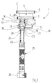
- the main components of the exploded view of Figure 1 are a floor which can be assembled from two parts 4, 5 1 a sanitary mixer tap, like this one for and for is known, and a water supply hose 25, the detachable to the bottom without the aid of soldering 1 to be attached.
- the upper bottom part 4 has an upper flange-like Area 2 and a lower flange-like area 3 on.
- an O-ring seal 6 and 7 respectively when attaching the bottom 1 in the only in figure 4 valve body 30 partially shown the seal take over against this.
- the upper bottom part 4 has two axial water through holes 28, of which only one in the drawing is visible. These water through holes 28 extend up to the upper face of the upper floor part 4. There is the fully assembled sanitary fitting a control cartridge 31 ( Figure 4) so that the Water flowing into the control cartridge via the bore 28 can reach.
- the upper bottom part 4 can be on the lower bottom part 5 with the help of locking tabs 8, which of protrude from the underside of the upper base part 4 downwards and can snap into place on the bottom part 5 that the bottom parts 4, 5 to form the entire bottom 1 are attached to each other, as shown in Figure 3 brought.
- the lower base part 5 also points to the through holes 28 of the upper base part 4 in alignment, two through holes 16 on that an upper in diameter enlarged area 13 and a lower one in diameter has a smaller area 18.
- the water supply hose 25 is at its bottom 1 the end facing the sanitary fitting with a rigid metallic receptacle 22 provided at its free End with a bevel 23 and at a certain distance provided with a circumferential ring groove 24 from this end is.
- the water supply hose 25 carries a connecting nut 26 which in a known manner Connection of the water supply hose 25 to the house line serves.
- detachable plug connection of the socket 22 of the water supply hose 25 are additional an O-ring for the main components already described 14, a retaining ring 12 and one with a slot 21 provided snap ring 20 required.
- the retaining ring 12 is already factory-fitted in the Diameter enlarged area 13 of the through hole 16 of the lower bottom part 5 used.
- This in diameter extended area 13 has such a height that above the retaining ring 12 in it the O-ring 14th there is enough space for it to survive slightly.
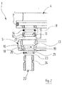
- the upper base part 4 like that of FIG. 3 can be seen with the help of the locking tabs 3 on the lower bottom part 5 plugged in and attached to this.
- the O-ring 14 is compressed so far that the Transition area between the through holes 16 in the bottom part 5 and 28 in the top part 4 is sealed to the outside.
- the lower region 27 of the through hole of the retaining ring 12 has a slightly larger diameter than the area 18 adjacent to the bottom, which is smaller Diameter of the through hole 16 of the lower bottom part 5.
- the upper region 11 of this through hole on the other hand, has the same diameter as the lower area 18 of the through hole 16 and the through hole 28 in the upper bottom part 4. In this way it is created between the retaining ring 12 and the step of the through hole 16 of the lower bottom part 5 a receiving space 40 for the first time outside the ground 1 the snap ring 20.
- the fully assembled floor 1 is then factory mounted in the valve body 30.
- the snap ring 20 is expanded with the help of its slot 21 and in the circumferential groove 24 on the socket 22 of the water supply hose 2 used.
- the outer and inner diameters of the snap ring 20 are included dimensioned as follows:
- the snap ring 20 In a relaxed state, as shown in Figures 1, 2 and 3, the snap ring 20 has an outer diameter on which is roughly the diameter of the lower area 27 corresponds to the through bore of the retaining ring 12; the inner diameter in the relaxed state is smaller than the outer diameter of the receptacle 22 of the water supply hose 25.
- the depth of the groove 24 in the receptacle 22 is so large that the snap ring 20 up to an outer diameter that can be compressed equal to the diameter of the lower region 18 of the Through hole 16 in the lower bottom part 5 is.
- the sanitary fitting described is installed on site by the sanitary fitter at the desired location, e.g. on one Vanity, attached.
- the receptacle 22 with the snap ring 20 is used from below against the through hole 16 of the lower bottom part 5 out. Due to a bevel 19 in the lower area The opening of this through bore 16 becomes the snap ring 20 compressed so far within the groove 24 of the socket 22, until its outside diameter matches the diameter of the reached lower region 18 of the through hole 16 Has. Now the receptacle 22 with the snap ring can be 20 through this area 18 of the through hole 16 push through until the snap ring 20 in the receiving space 40 has arrived. There he can, as in FIG remove, spring open and lock the axial movement the receptacle 22 within the through hole 16 of the bottom part 5.
Landscapes
- Engineering & Computer Science (AREA)
- General Engineering & Computer Science (AREA)
- Health & Medical Sciences (AREA)
- Life Sciences & Earth Sciences (AREA)
- Hydrology & Water Resources (AREA)
- Public Health (AREA)
- Water Supply & Treatment (AREA)
- Mechanical Engineering (AREA)
- Domestic Plumbing Installations (AREA)
- Quick-Acting Or Multi-Walled Pipe Joints (AREA)
- Supports For Pipes And Cables (AREA)
- Valve Housings (AREA)
Applications Claiming Priority (2)
| Application Number | Priority Date | Filing Date | Title |
|---|---|---|---|
| DE19911574A DE19911574C2 (de) | 1999-03-16 | 1999-03-16 | Sanitärarmatur |
| DE19911574 | 1999-03-16 |
Publications (2)
| Publication Number | Publication Date |
|---|---|
| EP1036973A1 true EP1036973A1 (fr) | 2000-09-20 |
| EP1036973B1 EP1036973B1 (fr) | 2002-10-23 |
Family
ID=7901091
Family Applications (1)
| Application Number | Title | Priority Date | Filing Date |
|---|---|---|---|
| EP00102483A Revoked EP1036973B1 (fr) | 1999-03-16 | 2000-02-05 | Armature sanitaire |
Country Status (5)
| Country | Link |
|---|---|
| EP (1) | EP1036973B1 (fr) |
| AT (1) | ATE226700T1 (fr) |
| DE (2) | DE19911574C2 (fr) |
| ES (1) | ES2182741T3 (fr) |
| PL (1) | PL195406B1 (fr) |
Cited By (4)
| Publication number | Priority date | Publication date | Assignee | Title |
|---|---|---|---|---|
| FR2858374A1 (fr) * | 2003-07-29 | 2005-02-04 | Delphi Tech Inc | Electrovalve, procede d'assemblage d'un solenoide sur ladite electrovalve, et procede de desassemblage du solenoide de ladite electrovalve |
| WO2008120252A1 (fr) * | 2007-03-30 | 2008-10-09 | Crs S.P.A. | Robinet |
| WO2010062331A1 (fr) * | 2008-10-28 | 2010-06-03 | Kohler Co. | Ensemble de logement de pulvérisateur |
| US9657874B2 (en) | 2014-04-25 | 2017-05-23 | Kohler Co. | Plumbing fitting adapter |
Families Citing this family (3)
| Publication number | Priority date | Publication date | Assignee | Title |
|---|---|---|---|---|
| DE10234206A1 (de) * | 2002-07-19 | 2004-01-29 | Hansgrohe Ag | Steckverbindung für Sanitärarmaturen |
| DE10311801A1 (de) * | 2003-03-12 | 2004-09-23 | Hansgrohe Ag | Einrichtung zum Befestigen einer Leitung |
| DE102019104774A1 (de) * | 2019-02-26 | 2020-08-27 | Grohe Ag | Sicherungselement zum Sichern von Leitungen im Sanitärbereich |
Citations (3)
| Publication number | Priority date | Publication date | Assignee | Title |
|---|---|---|---|---|
| US4645245A (en) * | 1985-10-07 | 1987-02-24 | General Motors Corporation | Quick connect tube coupling |
| EP0681127A1 (fr) * | 1994-05-05 | 1995-11-08 | Friedrich Grohe Aktiengesellschaft | Robinet d'eau |
| US5685341A (en) * | 1996-09-10 | 1997-11-11 | Amerikam, Inc. | Water faucet with quick-connect socket |
Family Cites Families (4)
| Publication number | Priority date | Publication date | Assignee | Title |
|---|---|---|---|---|
| DE3405229A1 (de) * | 1984-02-14 | 1985-09-05 | Hermann Ing.(grad.) 7210 Rottweil Breucha | Anschlussstueck fuer schlauchleitungen |
| DE19512721C1 (de) * | 1995-04-05 | 1996-10-10 | Cgs Analysen Mess Und Regeltec | Steckkupplung, insbesondere für eine beheizte Schlauchleitung |
| DE29509041U1 (de) * | 1995-06-01 | 1995-08-24 | Gebrüder Kemper GmbH + Co Metallwerke, 57462 Olpe | Vorrichtung zur Verbindung von Rohren o.dgl. rohrförmigen Armaturenteilen mit einer Armatur für fluide Medien |
| EP0898109B1 (fr) * | 1997-08-19 | 2003-05-21 | Johannes Schäfer vormals Stettiner Schraubenwerke GmbH & Co. KG | Raccord emboitable pour tuyaux |
-
1999
- 1999-03-16 DE DE19911574A patent/DE19911574C2/de not_active Expired - Fee Related
-
2000
- 2000-02-05 EP EP00102483A patent/EP1036973B1/fr not_active Revoked
- 2000-02-05 DE DE50000666T patent/DE50000666D1/de not_active Revoked
- 2000-02-05 AT AT00102483T patent/ATE226700T1/de not_active IP Right Cessation
- 2000-02-05 ES ES00102483T patent/ES2182741T3/es not_active Expired - Lifetime
- 2000-03-09 PL PL338913A patent/PL195406B1/pl not_active IP Right Cessation
Patent Citations (4)
| Publication number | Priority date | Publication date | Assignee | Title |
|---|---|---|---|---|
| US4645245A (en) * | 1985-10-07 | 1987-02-24 | General Motors Corporation | Quick connect tube coupling |
| EP0681127A1 (fr) * | 1994-05-05 | 1995-11-08 | Friedrich Grohe Aktiengesellschaft | Robinet d'eau |
| EP0681127B1 (fr) | 1994-05-05 | 1998-07-15 | Friedrich Grohe Aktiengesellschaft | Robinet d'eau |
| US5685341A (en) * | 1996-09-10 | 1997-11-11 | Amerikam, Inc. | Water faucet with quick-connect socket |
Cited By (7)
| Publication number | Priority date | Publication date | Assignee | Title |
|---|---|---|---|---|
| FR2858374A1 (fr) * | 2003-07-29 | 2005-02-04 | Delphi Tech Inc | Electrovalve, procede d'assemblage d'un solenoide sur ladite electrovalve, et procede de desassemblage du solenoide de ladite electrovalve |
| WO2005015582A1 (fr) * | 2003-07-29 | 2005-02-17 | Delphi Technologies, Inc. | Electrovalve, procede d'assemblage d'un solenoïde sur ladite electrovalve, et procede de desassemblage du solenoïde de ladite electrovalve |
| US7618018B2 (en) | 2003-07-29 | 2009-11-17 | Delphi Technologies, Inc. | Assembly comprising electrically operated valve, and process for assembling a solenoid on a housing of the valve |
| WO2008120252A1 (fr) * | 2007-03-30 | 2008-10-09 | Crs S.P.A. | Robinet |
| WO2010062331A1 (fr) * | 2008-10-28 | 2010-06-03 | Kohler Co. | Ensemble de logement de pulvérisateur |
| US8863769B2 (en) | 2008-10-28 | 2014-10-21 | Kohler Co. | Sprayer seating assembly |
| US9657874B2 (en) | 2014-04-25 | 2017-05-23 | Kohler Co. | Plumbing fitting adapter |
Also Published As
| Publication number | Publication date |
|---|---|
| DE19911574C2 (de) | 2003-05-08 |
| PL338913A1 (en) | 2000-09-25 |
| PL195406B1 (pl) | 2007-09-28 |
| DE19911574A1 (de) | 2000-11-02 |
| EP1036973B1 (fr) | 2002-10-23 |
| DE50000666D1 (de) | 2002-11-28 |
| ES2182741T3 (es) | 2003-03-16 |
| ATE226700T1 (de) | 2002-11-15 |
Similar Documents
| Publication | Publication Date | Title |
|---|---|---|
| EP1382757B1 (fr) | Bloc d'installation sanitaire | |
| DE102011085346B4 (de) | Sanitärarmatur | |
| DE102004040084B4 (de) | Sanitäre Unterputzarmatur | |
| EP1006244B1 (fr) | Dispositif de fixation pour éléments sanitaires | |
| EP1036973B1 (fr) | Armature sanitaire | |
| DE2527132C3 (de) | Anschlußvorrichtung für einen Heizkörper | |
| DE102013205250A1 (de) | Rohranschlussadapter und Sanitärarmatur | |
| DE3133267C2 (de) | Wasserauslauf-Armatur, insbesondere für sanitäre Zwecke | |
| EP1022500B1 (fr) | Robinet sanitaire, en particulier pour les lavabos | |
| DE3924795C2 (de) | Fluid-Anschlußeinrichtung | |
| EP2853643B1 (fr) | Système de corps de raccordement pour une robinetterie encastrée | |
| EP1724523A1 (fr) | Luminaire, en particulier pour un placard, une étagère ou équivalent | |
| DE952307C (de) | Selbsttaetige Rohr- oder Schlauchkupplung | |
| EP0762037A1 (fr) | Raccord vissé pour tuyaux | |
| DE10057229B4 (de) | Wandanschlussfitting für Armaturen | |
| DE102004061225B3 (de) | Sanitäre Wasserauslaufarmatur mit wenigstens einem Wasserauslaufrohr | |
| EP0780523B1 (fr) | Mitigeur avec conduites d'amenées inclinées | |
| EP0669504A1 (fr) | Couplage hydraulique | |
| EP1136629B1 (fr) | Armature sanitaire pour chasse d'eau | |
| EP0760444B1 (fr) | Armature sanitaire, notamment soupape thermostatique | |
| DE19961418A1 (de) | Einbaugarnitur mit lösbarem Glockenadapter | |
| EP1006241B1 (fr) | Armature sanitaire avec amortisseur de bruit | |
| DE2036708A1 (de) | Schutzvorrichtung für Rohrstutzen | |
| DE202022101408U1 (de) | Ablaufvorrichtung mit einem justierbaren Träger für eine Ablauf-Abdeckung | |
| WO2023174540A1 (fr) | Adaptateur pour dispositif de drainage |
Legal Events
| Date | Code | Title | Description |
|---|---|---|---|
| PUAI | Public reference made under article 153(3) epc to a published international application that has entered the european phase |
Free format text: ORIGINAL CODE: 0009012 |
|
| AK | Designated contracting states |
Kind code of ref document: A1 Designated state(s): AT BE CH CY DE DK ES FI FR GB GR IE IT LI LU MC NL PT SE |
|
| AX | Request for extension of the european patent |
Free format text: AL;LT;LV;MK;RO;SI |
|
| 17P | Request for examination filed |
Effective date: 20001230 |
|
| AKX | Designation fees paid |
Free format text: AT BE CH CY DE DK ES FI FR GB GR IE IT LI LU MC NL PT SE |
|
| GRAG | Despatch of communication of intention to grant |
Free format text: ORIGINAL CODE: EPIDOS AGRA |
|
| 17Q | First examination report despatched |
Effective date: 20020328 |
|
| GRAG | Despatch of communication of intention to grant |
Free format text: ORIGINAL CODE: EPIDOS AGRA |
|
| GRAH | Despatch of communication of intention to grant a patent |
Free format text: ORIGINAL CODE: EPIDOS IGRA |
|
| GRAH | Despatch of communication of intention to grant a patent |
Free format text: ORIGINAL CODE: EPIDOS IGRA |
|
| GRAA | (expected) grant |
Free format text: ORIGINAL CODE: 0009210 |
|
| AK | Designated contracting states |
Kind code of ref document: B1 Designated state(s): AT BE CH CY DE DK ES FI FR GB GR IE IT LI LU MC NL PT SE |
|
| PG25 | Lapsed in a contracting state [announced via postgrant information from national office to epo] |
Ref country code: FI Free format text: LAPSE BECAUSE OF FAILURE TO SUBMIT A TRANSLATION OF THE DESCRIPTION OR TO PAY THE FEE WITHIN THE PRESCRIBED TIME-LIMIT Effective date: 20021023 Ref country code: GB Free format text: LAPSE BECAUSE OF FAILURE TO SUBMIT A TRANSLATION OF THE DESCRIPTION OR TO PAY THE FEE WITHIN THE PRESCRIBED TIME-LIMIT Effective date: 20021023 Ref country code: GR Free format text: LAPSE BECAUSE OF FAILURE TO SUBMIT A TRANSLATION OF THE DESCRIPTION OR TO PAY THE FEE WITHIN THE PRESCRIBED TIME-LIMIT Effective date: 20021023 Ref country code: IE Free format text: LAPSE BECAUSE OF FAILURE TO SUBMIT A TRANSLATION OF THE DESCRIPTION OR TO PAY THE FEE WITHIN THE PRESCRIBED TIME-LIMIT Effective date: 20021023 |
|
| REF | Corresponds to: |
Ref document number: 226700 Country of ref document: AT Date of ref document: 20021115 Kind code of ref document: T |
|
| REG | Reference to a national code |
Ref country code: GB Ref legal event code: FG4D Free format text: NOT ENGLISH |
|
| REG | Reference to a national code |
Ref country code: CH Ref legal event code: EP |
|
| REG | Reference to a national code |
Ref country code: IE Ref legal event code: FG4D Free format text: GERMAN |
|
| REF | Corresponds to: |
Ref document number: 50000666 Country of ref document: DE Date of ref document: 20021128 |
|
| REG | Reference to a national code |
Ref country code: CH Ref legal event code: NV Representative=s name: FREI PATENTANWALTSBUERO |
|
| PG25 | Lapsed in a contracting state [announced via postgrant information from national office to epo] |
Ref country code: SE Free format text: LAPSE BECAUSE OF FAILURE TO SUBMIT A TRANSLATION OF THE DESCRIPTION OR TO PAY THE FEE WITHIN THE PRESCRIBED TIME-LIMIT Effective date: 20030123 Ref country code: PT Free format text: LAPSE BECAUSE OF FAILURE TO SUBMIT A TRANSLATION OF THE DESCRIPTION OR TO PAY THE FEE WITHIN THE PRESCRIBED TIME-LIMIT Effective date: 20030123 Ref country code: DK Free format text: LAPSE BECAUSE OF FAILURE TO SUBMIT A TRANSLATION OF THE DESCRIPTION OR TO PAY THE FEE WITHIN THE PRESCRIBED TIME-LIMIT Effective date: 20030123 |
|
| PG25 | Lapsed in a contracting state [announced via postgrant information from national office to epo] |
Ref country code: CY Free format text: LAPSE BECAUSE OF FAILURE TO SUBMIT A TRANSLATION OF THE DESCRIPTION OR TO PAY THE FEE WITHIN THE PRESCRIBED TIME-LIMIT Effective date: 20030205 Ref country code: LU Free format text: LAPSE BECAUSE OF NON-PAYMENT OF DUE FEES Effective date: 20030205 |
|
| PG25 | Lapsed in a contracting state [announced via postgrant information from national office to epo] |
Ref country code: MC Free format text: LAPSE BECAUSE OF NON-PAYMENT OF DUE FEES Effective date: 20030228 |
|
| REG | Reference to a national code |
Ref country code: ES Ref legal event code: FG2A Ref document number: 2182741 Country of ref document: ES Kind code of ref document: T3 |
|
| GBV | Gb: ep patent (uk) treated as always having been void in accordance with gb section 77(7)/1977 [no translation filed] |
Effective date: 20021023 |
|
| ET | Fr: translation filed | ||
| REG | Reference to a national code |
Ref country code: IE Ref legal event code: FD4D Ref document number: 1036973E Country of ref document: IE |
|
| PLBI | Opposition filed |
Free format text: ORIGINAL CODE: 0009260 |
|
| PLAX | Notice of opposition and request to file observation + time limit sent |
Free format text: ORIGINAL CODE: EPIDOSNOBS2 |
|
| 26 | Opposition filed |
Opponent name: FRIEDRICH GROHE AG & CO. KG Effective date: 20030710 |
|
| NLR1 | Nl: opposition has been filed with the epo |
Opponent name: FRIEDRICH GROHE AG & CO. KG |
|
| PLAB | Opposition data, opponent's data or that of the opponent's representative modified |
Free format text: ORIGINAL CODE: 0009299OPPO |
|
| PLBB | Reply of patent proprietor to notice(s) of opposition received |
Free format text: ORIGINAL CODE: EPIDOSNOBS3 |
|
| R26 | Opposition filed (corrected) |
Opponent name: GROHE WATER TECHNOLOGY AG & CO. KG Effective date: 20030710 |
|
| PLAY | Examination report in opposition despatched + time limit |
Free format text: ORIGINAL CODE: EPIDOSNORE2 |
|
| NLR1 | Nl: opposition has been filed with the epo |
Opponent name: GROHE WATER TECHNOLOGY AG & CO. KG |
|
| PLBC | Reply to examination report in opposition received |
Free format text: ORIGINAL CODE: EPIDOSNORE3 |
|
| PLAY | Examination report in opposition despatched + time limit |
Free format text: ORIGINAL CODE: EPIDOSNORE2 |
|
| PLBC | Reply to examination report in opposition received |
Free format text: ORIGINAL CODE: EPIDOSNORE3 |
|
| PLAB | Opposition data, opponent's data or that of the opponent's representative modified |
Free format text: ORIGINAL CODE: 0009299OPPO |
|
| R26 | Opposition filed (corrected) |
Opponent name: GROHE WATER TECHNOLOGY AG & CO. KG Effective date: 20030710 |
|
| PLCK | Communication despatched that opposition was rejected |
Free format text: ORIGINAL CODE: EPIDOSNREJ1 |
|
| NLR1 | Nl: opposition has been filed with the epo |
Opponent name: GROHE WATER TECHNOLOGY AG & CO. KG |
|
| APBP | Date of receipt of notice of appeal recorded |
Free format text: ORIGINAL CODE: EPIDOSNNOA2O |
|
| APAH | Appeal reference modified |
Free format text: ORIGINAL CODE: EPIDOSCREFNO |
|
| APBQ | Date of receipt of statement of grounds of appeal recorded |
Free format text: ORIGINAL CODE: EPIDOSNNOA3O |
|
| APAH | Appeal reference modified |
Free format text: ORIGINAL CODE: EPIDOSCREFNO |
|
| PGFP | Annual fee paid to national office [announced via postgrant information from national office to epo] |
Ref country code: CH Payment date: 20080229 Year of fee payment: 9 Ref country code: ES Payment date: 20080215 Year of fee payment: 9 |
|
| PGFP | Annual fee paid to national office [announced via postgrant information from national office to epo] |
Ref country code: IT Payment date: 20080228 Year of fee payment: 9 Ref country code: NL Payment date: 20080229 Year of fee payment: 9 |
|
| PGFP | Annual fee paid to national office [announced via postgrant information from national office to epo] |
Ref country code: AT Payment date: 20080229 Year of fee payment: 9 |
|
| PGFP | Annual fee paid to national office [announced via postgrant information from national office to epo] |
Ref country code: DE Payment date: 20080409 Year of fee payment: 9 Ref country code: FR Payment date: 20080229 Year of fee payment: 9 |
|
| PGFP | Annual fee paid to national office [announced via postgrant information from national office to epo] |
Ref country code: BE Payment date: 20080312 Year of fee payment: 9 |
|
| APBU | Appeal procedure closed |
Free format text: ORIGINAL CODE: EPIDOSNNOA9O |
|
| RDAF | Communication despatched that patent is revoked |
Free format text: ORIGINAL CODE: EPIDOSNREV1 |
|
| RDAG | Patent revoked |
Free format text: ORIGINAL CODE: 0009271 |
|
| STAA | Information on the status of an ep patent application or granted ep patent |
Free format text: STATUS: PATENT REVOKED |
|
| REG | Reference to a national code |
Ref country code: CH Ref legal event code: PL |
|
| 27W | Patent revoked |
Effective date: 20090109 |
|
| NLR2 | Nl: decision of opposition |
Effective date: 20090109 |
|
| PLAB | Opposition data, opponent's data or that of the opponent's representative modified |
Free format text: ORIGINAL CODE: 0009299OPPO |
|
| R26 | Opposition filed (corrected) |
Opponent name: GROHE WATER TECHNOLOGY AG & CO. KG Effective date: 20030710 |