EP1040954A2 - Antriebswelle für Kraftfahrzeug - Google Patents
Antriebswelle für Kraftfahrzeug Download PDFInfo
- Publication number
- EP1040954A2 EP1040954A2 EP00302632A EP00302632A EP1040954A2 EP 1040954 A2 EP1040954 A2 EP 1040954A2 EP 00302632 A EP00302632 A EP 00302632A EP 00302632 A EP00302632 A EP 00302632A EP 1040954 A2 EP1040954 A2 EP 1040954A2
- Authority
- EP
- European Patent Office
- Prior art keywords
- section
- propeller shaft
- bulging
- grade surface
- grade
- Prior art date
- Legal status (The legal status is an assumption and is not a legal conclusion. Google has not performed a legal analysis and makes no representation as to the accuracy of the status listed.)
- Withdrawn
Links
- 230000005540 biological transmission Effects 0.000 claims description 3
- 238000013459 approach Methods 0.000 description 3
- 238000000034 method Methods 0.000 description 3
- 238000005549 size reduction Methods 0.000 description 3
- 230000004323 axial length Effects 0.000 description 2
- 238000006073 displacement reaction Methods 0.000 description 2
- 238000005516 engineering process Methods 0.000 description 2
- 230000002411 adverse Effects 0.000 description 1
- 230000015572 biosynthetic process Effects 0.000 description 1
- 230000003247 decreasing effect Effects 0.000 description 1
- 238000010586 diagram Methods 0.000 description 1
- 230000000694 effects Effects 0.000 description 1
- 238000012986 modification Methods 0.000 description 1
- 230000004048 modification Effects 0.000 description 1
Images






Classifications
-
- F—MECHANICAL ENGINEERING; LIGHTING; HEATING; WEAPONS; BLASTING
- F16—ENGINEERING ELEMENTS AND UNITS; GENERAL MEASURES FOR PRODUCING AND MAINTAINING EFFECTIVE FUNCTIONING OF MACHINES OR INSTALLATIONS; THERMAL INSULATION IN GENERAL
- F16C—SHAFTS; FLEXIBLE SHAFTS; ELEMENTS OR CRANKSHAFT MECHANISMS; ROTARY BODIES OTHER THAN GEARING ELEMENTS; BEARINGS
- F16C3/00—Shafts; Axles; Cranks; Eccentrics
- F16C3/02—Shafts; Axles
-
- B—PERFORMING OPERATIONS; TRANSPORTING
- B60—VEHICLES IN GENERAL
- B60K—ARRANGEMENT OR MOUNTING OF PROPULSION UNITS OR OF TRANSMISSIONS IN VEHICLES; ARRANGEMENT OR MOUNTING OF PLURAL DIVERSE PRIME-MOVERS IN VEHICLES; AUXILIARY DRIVES FOR VEHICLES; INSTRUMENTATION OR DASHBOARDS FOR VEHICLES; ARRANGEMENTS IN CONNECTION WITH COOLING, AIR INTAKE, GAS EXHAUST OR FUEL SUPPLY OF PROPULSION UNITS IN VEHICLES
- B60K17/00—Arrangement or mounting of transmissions in vehicles
- B60K17/22—Arrangement or mounting of transmissions in vehicles characterised by arrangement, location, or type of main drive shafting, e.g. cardan shaft
Definitions
- the present invention relates to a propeller shaft for a vehicle, more particularly, to a vehicular propeller shaft capable of absorbing an impulse by being deformed axially when an impulse load is applied in the longitudinal direction of the vehicle.
- a vehicle is constituted so as to transmit engine power from a transmission to a differential through a propeller shaft and from the differential to wheels.
- the propeller shaft is disposed in the transverse centre of the vehicle and extending in the longitudinal direction.
- the deformation of the vehicle body is blocked by a lengthwise resistance of the propeller shaft and as a result a large impulse is caused in the vehicle.
- Japanese Patent Application Laid-open No. Toku-Kai-Hei 5-178105 discloses a technique in which a propeller shaft is formed in the shape of a cylindrical tube to enhance the specific torsional stiffness (i.e torsional stiffness per unit weight). Also, the propeller shaft has an annular bulge formed in its radial direction. When an excessively large impulse is applied to the vehicle, the bulge is deformed so that the propeller shaft is released from a state of lengthwise resistance.
- a propeller shaft 100 comprising a hollow propeller shaft 101, a centre support bearing 102 provided at the rear end of the propeller shaft 100 and a bellows pipe 103 connected in the front thereof with the hollow propeller shaft 101 and connected in the rear thereof with the centre support bearing 102.
- the bellows pipe 103 is deformed so that the propeller shaft 100 can be released from the state of lengthwise resistance.
- Fig. 9a shows a propeller shaft 111 disclosed by Japanese Patent Application Laid-open No. Toku-Kai-Hei 8- 226454.
- the propeller shaft 111 comprises a female member 112 and a male member 113 splined on to the female member 112.
- the female member 112 comprises a small diameter portion 112a and a large diameter portion 112b and the small diameter portion 112a is splined over the male member 113. Therefore, a step portion 112c is formed on the propeller shaft 111 between the small diameter portion 112a and the large diameter portion 112b.
- step portion 112c When an impulse is applied to propeller shaft 111 in the longitudinal direction, as shown in Fig. 9b, the step portion 112c is deformed or broken in the axial direction to absorb the impulse.
- the problem is that since the deformation or breakage in the axial direction requires a large impulse load, especially, a large impulse load at the initial stage, the propeller shaft 111 still has a difficulty in alleviating the impulse effectively.
- the invention provides a propeller shaft according to claim 1.
- each bulging section bulges radially out from the surface of the shaft and presents a trapezoid cross section at the outwardly bulging part constituted by an up-grade surface, a down-grade surface and a top surface provided between said up-grade surface and said down-grade surface.
- a propeller shaft 1 comprises a first propeller shaft 10 which is connected at the front end thereof with a main shaft (not shown) of a transmission (not shown) via a universal joint 21 and which is rotatably supported at the rear end thereof by a centre bearing 22 and a second propeller shaft 30 which is connected at the front end thereof with the first propeller shaft 10 via a universal joint 24 and which connected at the rear end thereof with a rear differential (not shown) via a universal joint 23.
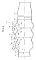
- the first propeller shaft 10 is tubular (i.e. hollow) to enhance the specific stiffness (i.e. stiffness/unit weight), as shown in Fig. 3.
- the first propeller shaft 10 is connected at the front end thereof with a joint yoke 21a and connected at the rear end thereof with a spline shaft 24a of the universal joint 24 which is rotatably supported by the centre bearing 22.
- a bellows shaped 1 section 11 is formed near the front end of the first propeller shaft 10.
- Fig. 3 shows an enlarged sectional view of the portion "A" in Fig. 2.
- the portion "A” is integrally connected on the front side thereof with a small diameter section 12 and is integrally connected on the rear side thereof with a large diameter section 13.
- the bellow shaped section 11 has three consecutive bulging sections 14, 15 and 16 each having a trapezoid cross section respectively and are annularly provided between the small diameter section 12 and the large diameter section 13 of the bellows section 11.
- a first bulging section 14 has a trapezoid cross section constituted by an annular first up-grade surface 14A, an annular first top surface 14B and an annular first down-grade 14C
- a second bulging section 15 has a trapezoid cross section constituted by an annular second up-grade surface 15A, an annular second top surface 15B and an annular second down-grade surface 15C
- a third bulging section 16 has a trapezoid cross section constituted by an annular third up-grade surface 16A, an annular third top surface 16B and an annular third down-grade surface 16C.
- the first bulging section 14 is integrally connected at the front end thereof with the small diameter section 12 via a bend portion 17
- the second bulging section 15 is integrally connected at the front end thereof with the rear end of the first bulging section 14 via a valley portion 18
- the third bulging section 16 is integrally connected at the front end thereof with the rear end of the second bulging section 15 and it is integrally connected at the rear end thereof with the large diameter section 13 via a second bend portion 20.
- Diameters d1, d2, d3 and d4 of the small diameter section 12, the first valley 18, the second valley 19 and the large diameter section 20, respectively are established to be d1 ⁇ d2 d3 ⁇ d4.
- ⁇ 1 represents an angle at which the first up-grade surface 14A meets a plane perpendicular to an axis of the first propeller shaft 10
- ⁇ 2 an angle at which the first down-grade surface 14C meets that plane
- ⁇ 3 an angle at which the second up-grade surface 15A meets the plane
- ⁇ 4 an angle at which the second down-grade surface 15C meets that plane
- ⁇ 5 an angle at which the third up-grade surface 16A meets the plane
- ⁇ 6 an angle at which the third down-grade surface 16C meets the plane
- Each annular top surface 14B, 15B and 16B may be formed between a first fold joining the up-grade surface with the annular top surface and a second fold joining then annular top surface with the corresponding down grade surface.
- Each Annular top surface may be of relatively constant radius over an axial length greater than the height (i.e., the difference in the radius of the trough and the radius of the annular top surface) of the bulge above the trough.
- Each annular section may have a section of relatively constant radius over an axial length sufficient to allow the annular section to deform over a circumferential region remote from its junctions with the upgrade and down grade surfaces as illustrated in figures 4a to 4e.
- Figs. 4a through 4e show deformation modes of the bellows shaped section 11 of thus formed propeller shaft 1, when an impulse load P larger than a certain (critical) value is applied to the propeller shaft 1 in the lengthwise direction.
- Figs. 4b, 4c, 4d and 4e show changes of deformation mode in order.
- Fig. 5 is a graph showing a relationship between load and displacement and symbols b, c, d and e correspond to modes of deformation of the propeller shaft 1 in Figs. 4b, 4c, 4d and 4e, respectively.
- the bend portion 17 approaches the first valley portion 18. Then, the top surface 14B is deformed and at the same time the second corner 14b/14c bends. As shown in Fig. 4c, since the inclination ⁇ 1 of the first up-grade surface 14A is smaller than the inclination ⁇ 2, the first up-grade surface 14A submerges under the first top surface 14B and the first up-grade surface 14A and the first top surface 14B are crushed toward the first down-grade surface 14C in such a way that the first bend portion 17 abuts against the first valley portion 18. Thus, during this deformation process of the first bulging section 14, the impulse energy up to the portion "c" of Fig. 5 is absorbed.
- the second top surface 15B and the second valley portion 19 are mainly bent and the second bulging section 15, as shown in Fig. 4d, is crushed in such a way that the second up-grade surface 15A approaches the second down-grade surface 15C.
- the impulse energy up to the portion "d" of Fig. 5 is absorbed.
- the third top surface 16B and the second bend portion 20 are mainly bent due to the concentration of stress, the third bulging section 16 is crushed, as shown in Fig. 4e, such that the third up-grade surface 16A covers the third down-grade surface 16C from above, thus the bellows shaped section 11 is deformed and the impulse energy up to the portion "e" of Fig. 5 is absorbed.
- the bend portion 17 submerges under the first valley portion 18.
- the bend portion 17 slides under the first valley portion 18 and never abuts the first valley portion 18.
- the diameter d2 of the first valley section 18 is established to be equal to or smaller than the diameter d3 of the second valley section 19 and the inclination ⁇ 3 of the second up-grade surface 15A is established to be larger than the inclination ⁇ 4 of the second down-grade surface 15C, the second bulging section 15 is crushed such that the second up-grade surface 15 reaches the second down-grade surface 15C, the impact energy is absorbed.
- the second valley portion 19 Since the diameter d3 of the second valley portion 19 is smaller than the diameter d4 of the large diameter section 13 and the inclination angle ⁇ 5 of the third up-grade surface 16A is established to be larger than the inclination angle ⁇ 6 of the third down-grade surface 16C, when the impulse load is applied to the bellows shaped section 11 in the axial direction, the second valley portion 19 submerges under the second bend portion 20. At this moment, when the impulse load is applied to the bellows shaped section 11, the second valley portion 19 slides under the second bend portion 20 and it never abuts the second bend portion 20.
- first bend portion 17, the first valley portion 18, the second valley portion 19 and the second bend portion 20 are deformed such that the first bend portion 17 and the second bend portion 20 submerge under the bellows shaped section 11 without abutting between these portions 17, 18, 19 and 20.
- the propeller shaft 1 secures an adequate crush stroke and can relieved the lengthwise resistance of the propeller shaft.
- the bellows shaped section 11 is constituted by small numbers of bulging sections, the first bulging section 14, the second bulging section 15 and the third bulging section 16, vehicle safety can be improved without reducing the critical speed of the propeller shaft.
- the bellows shaped section 11 is formed only at the front portion of the first propeller shaft 1, the components after the centre bearing 22 can be used as they are in the prior art.
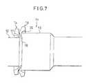
- a propeller shaft according to a second embodiment of the present invention will be described by reference to Figs. 6 and 7.
- the components of the propeller shaft which are identical in both embodiments are denoted by identical reference numbers and are not described in detail.
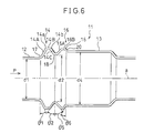
- Fig. 6 is an enlarged sectional view of a bellows shaped section 11 which corresponds to Fig. 3 according to the first embodiment.
- the bellows shaped section 11 has a small diameter section 12 and a large diameter section 13.
- a first bulging section 14 and a third bulging section 16 are annularly formed consecutively between the small diameter section 12 and the large diameter section 13.
- the small diameter section 12, first bulging section 14, third bulging section 16 and large diameter section 13 are formed consecutively via a first bend portion 17, a first valley portion 18 and a second bend portion 20.
- reference numerals d1, d2 and d4 denote the diameters of the small diameter section 12, the first valley portion 18 and the large diameter section 13, respectively and the diameters d1, d2 and d4 are established so as to be d1 ⁇ d2 ⁇ d4.
- reference numerals ⁇ 1, ⁇ 2, ⁇ 5 and ⁇ 6 denote angles at which a plane perpendicular to the axis a of the propeller shaft 10 meets a first up-grade surface 14A, a first down-grade surface 14C, a third up-grade surface 16A and a third down-grade surface 16C, respectively and these angles are established to be ⁇ 1 ⁇ ⁇ 2 and ⁇ 5 > ⁇ 6.
- the first bend portion 17 approaches the first valley portion 18 and a second corner 14b where the first top surface 14B turns to the first down-grade surface 14C is bent outwardly. Further, since the inclination angle ⁇ 1 of the first up-grade surface 14A is established to be smaller than the inclination angle ⁇ 2 of the first down-grade surface 14C, the first up-grade surface 14A slidably submerges under the first down-grade 14C, while the first bend portion 17 and the first valley portion 18 are crushed. Thus, impulse energy is absorbed by the size reduction of the bellows shaped section 11.
- the first valley portion 18 whose diameter is formed so as to be larger than the small diameter section 12 and smaller than the large diameter section 13, is deformed and the third up-grade surface 16A is crushed by the up-coming first down-grade surface 14C to absorb impulse energy.
- the first valley portion 18 and the large diameter section 13 respectively are established to be d1 ⁇ d2 ⁇ d4, in the same manner as the first embodiment, the first bend portion 17 which is formed at the end of the small diameter section 12 has a small diameter, the first valley portion 18 and the second bend portion 20, are deformed in this order.
- the inclination angles ⁇ 1, ⁇ 2 of the first up-grade surface 14A and the first down-grade surface 14C respectively are established to be ⁇ 1 ⁇ ⁇ 2 and the inclination angles ⁇ 5, ⁇ 6 of the third up-grade surface 16A and the third down-grade surface 16C respectively are established to be ⁇ 5 > ⁇ 6, a time difference is generated between the deformation of the first bulging section 14 and the deformation of the third bulging section 16. Accordingly, the bellows shaped section 11 can be deformed with a relatively small impulse load and the initial load is properly controlled to alleviate the impulse effectively.
- first bend portion 17 and the first valley portion 18 submerge under the large diameter section 13, while they are deformed, without collisions between the first bend portion 17, the first valley portion 18 and the second bend portion 20, an adequate crash stroke can be secured and the lengthwise resistance of the propeller shaft 11 can be avoided when an impulse is applied.
- the bellows shaped section 11 is formed at the front portion of the first propeller shaft 10, however, it is possible to dispose the bellows shaped section 11 in the vicinity of the rear portion of the first propeller shaft 10. Further, the number of bulging sections is not limited to two or three and it is possible to increase the number of bulging sections of the bellows shaped section within an allowable range of the reduction in critical speed of the propeller shaft 11.
Landscapes
- Engineering & Computer Science (AREA)
- General Engineering & Computer Science (AREA)
- Mechanical Engineering (AREA)
- Ocean & Marine Engineering (AREA)
- Chemical & Material Sciences (AREA)
- Combustion & Propulsion (AREA)
- Transportation (AREA)
- Shafts, Cranks, Connecting Bars, And Related Bearings (AREA)
- Motor Power Transmission Devices (AREA)
- Diaphragms And Bellows (AREA)
Applications Claiming Priority (2)
| Application Number | Priority Date | Filing Date | Title |
|---|---|---|---|
| JP8862499 | 1999-03-30 | ||
| JP11088624A JP2000283139A (ja) | 1999-03-30 | 1999-03-30 | 車両用プロペラシャフト |
Publications (2)
| Publication Number | Publication Date |
|---|---|
| EP1040954A2 true EP1040954A2 (de) | 2000-10-04 |
| EP1040954A3 EP1040954A3 (de) | 2004-08-11 |
Family
ID=13947972
Family Applications (1)
| Application Number | Title | Priority Date | Filing Date |
|---|---|---|---|
| EP00302632A Withdrawn EP1040954A3 (de) | 1999-03-30 | 2000-03-29 | Antriebswelle für Kraftfahrzeug |
Country Status (3)
| Country | Link |
|---|---|
| US (1) | US6328656B1 (de) |
| EP (1) | EP1040954A3 (de) |
| JP (1) | JP2000283139A (de) |
Cited By (1)
| Publication number | Priority date | Publication date | Assignee | Title |
|---|---|---|---|---|
| GB2358902A (en) * | 2000-02-03 | 2001-08-08 | Dana Corp | Collapsible drive shaft |
Families Citing this family (24)
| Publication number | Priority date | Publication date | Assignee | Title |
|---|---|---|---|---|
| SE517177C2 (sv) * | 2000-03-09 | 2002-04-23 | Volvo Lastvagnar Ab | Axelkoppling |
| US20030236122A1 (en) * | 2002-06-24 | 2003-12-25 | Gkn Automotive, Inc. | Propeller shaft assembly |
| US6997813B2 (en) * | 2002-06-24 | 2006-02-14 | Gkn Driveline North America, Inc. | Rotary shaft |
| US20040157670A1 (en) * | 2003-02-06 | 2004-08-12 | James Lyon | Propshaft having multiple crash features |
| US20060009297A1 (en) * | 2004-07-08 | 2006-01-12 | Hubiak William R | Flexible coupling having a center with opposing re-entrant folds |
| US7175532B2 (en) * | 2004-01-09 | 2007-02-13 | Daimlerchrysler Corporation | Energy absorbing propeller shaft system |
| US20060035714A1 (en) * | 2004-08-13 | 2006-02-16 | Yi Qu | Collapsible vehicle driveshaft |
| US20060094513A1 (en) * | 2004-10-29 | 2006-05-04 | Eastman Kodak Company | Coupling apparatus |
| US20060094514A1 (en) * | 2004-10-29 | 2006-05-04 | Eastman Kodak Company | Flexible coupling |
| US7275332B2 (en) * | 2005-02-22 | 2007-10-02 | Carestream Health, Inc. | Multi-axis positioning apparatus |
| JP4945253B2 (ja) * | 2007-01-30 | 2012-06-06 | 株式会社ショーワ | 自動車用衝撃吸収プロペラシャフト装置 |
| JP2009006956A (ja) * | 2007-06-29 | 2009-01-15 | Jtekt Corp | 衝撃吸収式車両用操舵装置 |
| JP2009006955A (ja) * | 2007-06-29 | 2009-01-15 | Jtekt Corp | 衝撃吸収式車両用操舵装置 |
| JP2009029300A (ja) * | 2007-07-27 | 2009-02-12 | Jtekt Corp | 衝撃吸収式車両用操舵装置 |
| US7942635B1 (en) * | 2007-08-02 | 2011-05-17 | Florida Turbine Technologies, Inc. | Twin spool rotor assembly for a small gas turbine engine |
| JP2009056877A (ja) * | 2007-08-30 | 2009-03-19 | Jtekt Corp | 衝撃吸収式車両用操舵装置 |
| DE102010064025A1 (de) * | 2010-12-23 | 2012-06-28 | Abb Turbo Systems Ag | Berstschutz |
| JP6137512B2 (ja) * | 2012-11-08 | 2017-05-31 | デーナ、オータモウティヴ、システィムズ、グループ、エルエルシー | ドライブシャフト管を形成するための方法 |
| KR101363401B1 (ko) * | 2013-09-11 | 2014-02-14 | 한국델파이주식회사 | 중공 구동축 및 이의 제조 방법 |
| DE102015209110B4 (de) * | 2015-05-19 | 2022-08-18 | Bayerische Motoren Werke Aktiengesellschaft | Anschlussvorrichtung für einen Antriebsstrang |
| US20180080503A1 (en) * | 2016-09-22 | 2018-03-22 | Goodrich Corporation | Bi-metal joints in shafts and couplings |
| US11493091B2 (en) * | 2017-08-25 | 2022-11-08 | Dana Automotive Systems, Group, Llc | Propeller shaft crash collapse assembly |
| US11486439B2 (en) | 2019-02-18 | 2022-11-01 | Hamilton Sundstrand Corporation | Drive shaft with non-cylindrical shape |
| US12467499B2 (en) | 2022-08-22 | 2025-11-11 | Hamilton Sundstrand Corporation | Drive shaft with non-cylindrical shape and spaced reinforcements |
Citations (2)
| Publication number | Priority date | Publication date | Assignee | Title |
|---|---|---|---|---|
| JPH05178105A (ja) | 1991-12-28 | 1993-07-20 | Suzuki Motor Corp | プロペラシャフト |
| JPH08226454A (ja) | 1995-02-22 | 1996-09-03 | Matsui Seisakusho:Kk | プロペラシャフト |
Family Cites Families (9)
| Publication number | Priority date | Publication date | Assignee | Title |
|---|---|---|---|---|
| US3487710A (en) * | 1967-02-17 | 1970-01-06 | Eaton Yale & Towne | Steering columns |
| FR2133343A5 (de) * | 1971-04-16 | 1972-11-24 | Glaenzer Spicer Sa | |
| US4304147A (en) * | 1980-01-23 | 1981-12-08 | The Torrington Company | Steering column |
| US4531619A (en) * | 1982-09-24 | 1985-07-30 | Eckels Robert E | Collapsible steering column |
| US4512209A (en) * | 1983-03-18 | 1985-04-23 | The Torrington Company | Steering column |
| DE4240237C2 (de) * | 1992-11-30 | 1995-02-16 | Gkn Automotive Ag | Stauchrohr |
| JP3094053B2 (ja) * | 1994-02-25 | 2000-10-03 | 富士機工株式会社 | 車両用ステアリング装置 |
| DE19645227A1 (de) * | 1996-11-02 | 1998-05-07 | Bayerische Motoren Werke Ag | Rohrförmiges Bauteil, insbesondere für eine Gelenkwelle |
| DE59809761D1 (de) * | 1997-04-16 | 2003-11-06 | Volkswagen Ag | Lenksäule für Insassenschutzeinrichtungen und Sicherheitslenkungen |
-
1999
- 1999-03-30 JP JP11088624A patent/JP2000283139A/ja active Pending
-
2000
- 2000-03-28 US US09/537,045 patent/US6328656B1/en not_active Expired - Fee Related
- 2000-03-29 EP EP00302632A patent/EP1040954A3/de not_active Withdrawn
Patent Citations (2)
| Publication number | Priority date | Publication date | Assignee | Title |
|---|---|---|---|---|
| JPH05178105A (ja) | 1991-12-28 | 1993-07-20 | Suzuki Motor Corp | プロペラシャフト |
| JPH08226454A (ja) | 1995-02-22 | 1996-09-03 | Matsui Seisakusho:Kk | プロペラシャフト |
Non-Patent Citations (1)
| Title |
|---|
| "list of unpatentable examples of automobile technologies no.95202", COMMITTEE OF INTELLECTUAL PROPERTIES OF JAPAN AUTOMOBILE MANUFACTURES ASSOCIATION, pages: FIG.8 |
Cited By (4)
| Publication number | Priority date | Publication date | Assignee | Title |
|---|---|---|---|---|
| GB2358902A (en) * | 2000-02-03 | 2001-08-08 | Dana Corp | Collapsible drive shaft |
| US6371859B1 (en) | 2000-02-03 | 2002-04-16 | Dana Corporation | Axially collapsible driveshaft assembly |
| GB2358902B (en) * | 2000-02-03 | 2004-03-10 | Dana Corp | Axially collapsible driveshaft assembly |
| AU776022B2 (en) * | 2000-02-03 | 2004-08-26 | Dana Corporation | Axially collapsible driveshaft assembly |
Also Published As
| Publication number | Publication date |
|---|---|
| US6328656B1 (en) | 2001-12-11 |
| EP1040954A3 (de) | 2004-08-11 |
| JP2000283139A (ja) | 2000-10-13 |
Similar Documents
| Publication | Publication Date | Title |
|---|---|---|
| EP1040954A2 (de) | Antriebswelle für Kraftfahrzeug | |
| AU740377B2 (en) | Collapsible vehicle driveshaft | |
| US6484384B1 (en) | Method of manufacturing an axially collapsible driveshaft assembly | |
| US7288029B1 (en) | Propshaft with crash-worthiness | |
| US5946977A (en) | Collapsible steering column | |
| EP1375943B1 (de) | Teleskopische Kupplung mit Kugeln die aus zwei Röhren besteht | |
| AU1676101A (en) | Axially collapsible driveshaft assembly | |
| JP6481797B2 (ja) | 伸縮シャフト | |
| CA1286119C (en) | Propeller shaft for motor vehicle | |
| US7442127B2 (en) | Propeller shaft and rotational power transmission mechanism equipped with this | |
| EP0704332A1 (de) | Mitnehmerscheibe für Kraftfahrzeug | |
| US7080436B2 (en) | Method of manufacturing an axially collapsible driveshaft | |
| JP6769393B2 (ja) | 車両用プロペラシャフト | |
| US7080437B2 (en) | Method of manufacturing an axially collapsible driveshaft assembly | |
| US20060217210A1 (en) | Axially collapsible driveshaft assembly | |
| CN110869631B (zh) | 万向接头和传动轴 | |
| JP6926797B2 (ja) | 伸縮シャフト | |
| GB2172376A (en) | Propeller shaft joints | |
| JP3583493B2 (ja) | プロペラシャフト | |
| US10941815B2 (en) | Connection device for a drive train | |
| EP1724035B1 (de) | Verfahren zur Herstellung einer Antriebseinheit | |
| JP2001311419A (ja) | プロペラシャフト | |
| KR20090013220U (ko) | 자동차의 충격 흡수 기능을 가진 프로펠러 샤프트 | |
| JP6528848B2 (ja) | ヨーク一体型シャフト及び伸縮軸 | |
| AU744548B1 (en) | Method of manufacturing an axially collapsible driveshaft assembly |
Legal Events
| Date | Code | Title | Description |
|---|---|---|---|
| PUAI | Public reference made under article 153(3) epc to a published international application that has entered the european phase |
Free format text: ORIGINAL CODE: 0009012 |
|
| AK | Designated contracting states |
Kind code of ref document: A2 Designated state(s): AT BE CH CY DE DK ES FI FR GB GR IE IT LI LU MC NL PT SE |
|
| AX | Request for extension of the european patent |
Free format text: AL;LT;LV;MK;RO;SI |
|
| PUAL | Search report despatched |
Free format text: ORIGINAL CODE: 0009013 |
|
| AK | Designated contracting states |
Kind code of ref document: A3 Designated state(s): AT BE CH CY DE DK ES FI FR GB GR IE IT LI LU MC NL PT SE |
|
| AX | Request for extension of the european patent |
Extension state: AL LT LV MK RO SI |
|
| 17P | Request for examination filed |
Effective date: 20040910 |
|
| AKX | Designation fees paid |
Designated state(s): DE GB |
|
| 17Q | First examination report despatched |
Effective date: 20050504 |
|
| RBV | Designated contracting states (corrected) |
Designated state(s): DE GB |
|
| GRAP | Despatch of communication of intention to grant a patent |
Free format text: ORIGINAL CODE: EPIDOSNIGR1 |
|
| STAA | Information on the status of an ep patent application or granted ep patent |
Free format text: STATUS: THE APPLICATION IS DEEMED TO BE WITHDRAWN |
|
| 18D | Application deemed to be withdrawn |
Effective date: 20060527 |