EP1041297A2 - Elément de montage - Google Patents
Elément de montage Download PDFInfo
- Publication number
- EP1041297A2 EP1041297A2 EP00106817A EP00106817A EP1041297A2 EP 1041297 A2 EP1041297 A2 EP 1041297A2 EP 00106817 A EP00106817 A EP 00106817A EP 00106817 A EP00106817 A EP 00106817A EP 1041297 A2 EP1041297 A2 EP 1041297A2
- Authority
- EP
- European Patent Office
- Prior art keywords
- connecting pin
- fastening sleeve
- fastening
- mounting element
- sleeve
- Prior art date
- Legal status (The legal status is an assumption and is not a legal conclusion. Google has not performed a legal analysis and makes no representation as to the accuracy of the status listed.)
- Withdrawn
Links
- 238000003780 insertion Methods 0.000 claims description 4
- 230000037431 insertion Effects 0.000 claims description 4
- 238000002347 injection Methods 0.000 claims description 3
- 239000007924 injection Substances 0.000 claims description 3
- 230000000284 resting effect Effects 0.000 abstract 1
- 238000000465 moulding Methods 0.000 description 3
- 210000000078 claw Anatomy 0.000 description 1
- 238000010276 construction Methods 0.000 description 1
- 238000004519 manufacturing process Methods 0.000 description 1
- 239000002184 metal Substances 0.000 description 1
- 238000010079 rubber tapping Methods 0.000 description 1
- 230000007704 transition Effects 0.000 description 1
Images


Classifications
-
- F—MECHANICAL ENGINEERING; LIGHTING; HEATING; WEAPONS; BLASTING
- F16—ENGINEERING ELEMENTS AND UNITS; GENERAL MEASURES FOR PRODUCING AND MAINTAINING EFFECTIVE FUNCTIONING OF MACHINES OR INSTALLATIONS; THERMAL INSULATION IN GENERAL
- F16B—DEVICES FOR FASTENING OR SECURING CONSTRUCTIONAL ELEMENTS OR MACHINE PARTS TOGETHER, e.g. NAILS, BOLTS, CIRCLIPS, CLAMPS, CLIPS OR WEDGES; JOINTS OR JOINTING
- F16B37/00—Nuts or like thread-engaging members
- F16B37/04—Devices for fastening nuts to surfaces, e.g. sheets, plates
- F16B37/041—Releasable devices
- F16B37/043—Releasable devices with snap action
-
- F—MECHANICAL ENGINEERING; LIGHTING; HEATING; WEAPONS; BLASTING
- F16—ENGINEERING ELEMENTS AND UNITS; GENERAL MEASURES FOR PRODUCING AND MAINTAINING EFFECTIVE FUNCTIONING OF MACHINES OR INSTALLATIONS; THERMAL INSULATION IN GENERAL
- F16B—DEVICES FOR FASTENING OR SECURING CONSTRUCTIONAL ELEMENTS OR MACHINE PARTS TOGETHER, e.g. NAILS, BOLTS, CIRCLIPS, CLAMPS, CLIPS OR WEDGES; JOINTS OR JOINTING
- F16B12/00—Jointing of furniture or the like, e.g. hidden from exterior
- F16B12/10—Jointing of furniture or the like, e.g. hidden from exterior using pegs, bolts, tenons, clamps, clips, or the like
- F16B12/12—Jointing of furniture or the like, e.g. hidden from exterior using pegs, bolts, tenons, clamps, clips, or the like for non-metal furniture parts, e.g. made of wood, of plastics
- F16B12/14—Jointing of furniture or the like, e.g. hidden from exterior using pegs, bolts, tenons, clamps, clips, or the like for non-metal furniture parts, e.g. made of wood, of plastics using threaded bolts or screws
-
- F—MECHANICAL ENGINEERING; LIGHTING; HEATING; WEAPONS; BLASTING
- F16—ENGINEERING ELEMENTS AND UNITS; GENERAL MEASURES FOR PRODUCING AND MAINTAINING EFFECTIVE FUNCTIONING OF MACHINES OR INSTALLATIONS; THERMAL INSULATION IN GENERAL
- F16B—DEVICES FOR FASTENING OR SECURING CONSTRUCTIONAL ELEMENTS OR MACHINE PARTS TOGETHER, e.g. NAILS, BOLTS, CIRCLIPS, CLAMPS, CLIPS OR WEDGES; JOINTS OR JOINTING
- F16B12/00—Jointing of furniture or the like, e.g. hidden from exterior
- F16B12/10—Jointing of furniture or the like, e.g. hidden from exterior using pegs, bolts, tenons, clamps, clips, or the like
- F16B12/12—Jointing of furniture or the like, e.g. hidden from exterior using pegs, bolts, tenons, clamps, clips, or the like for non-metal furniture parts, e.g. made of wood, of plastics
- F16B12/24—Jointing of furniture or the like, e.g. hidden from exterior using pegs, bolts, tenons, clamps, clips, or the like for non-metal furniture parts, e.g. made of wood, of plastics using separate pins, dowels, or the like
-
- F—MECHANICAL ENGINEERING; LIGHTING; HEATING; WEAPONS; BLASTING
- F16—ENGINEERING ELEMENTS AND UNITS; GENERAL MEASURES FOR PRODUCING AND MAINTAINING EFFECTIVE FUNCTIONING OF MACHINES OR INSTALLATIONS; THERMAL INSULATION IN GENERAL
- F16B—DEVICES FOR FASTENING OR SECURING CONSTRUCTIONAL ELEMENTS OR MACHINE PARTS TOGETHER, e.g. NAILS, BOLTS, CIRCLIPS, CLAMPS, CLIPS OR WEDGES; JOINTS OR JOINTING
- F16B13/00—Dowels or other devices fastened in walls or the like by inserting them in holes made therein for that purpose
- F16B13/12—Separate metal or non-separate or non-metal dowel sleeves fastened by inserting the screw, nail or the like
- F16B13/126—Separate metal or non-separate or non-metal dowel sleeves fastened by inserting the screw, nail or the like fastened by inserting an unthreaded element, e.g. pin or nail
-
- F—MECHANICAL ENGINEERING; LIGHTING; HEATING; WEAPONS; BLASTING
- F16—ENGINEERING ELEMENTS AND UNITS; GENERAL MEASURES FOR PRODUCING AND MAINTAINING EFFECTIVE FUNCTIONING OF MACHINES OR INSTALLATIONS; THERMAL INSULATION IN GENERAL
- F16B—DEVICES FOR FASTENING OR SECURING CONSTRUCTIONAL ELEMENTS OR MACHINE PARTS TOGETHER, e.g. NAILS, BOLTS, CIRCLIPS, CLAMPS, CLIPS OR WEDGES; JOINTS OR JOINTING
- F16B19/00—Bolts without screw-thread; Pins, including deformable elements; Rivets
- F16B19/04—Rivets; Spigots or the like fastened by riveting
- F16B19/08—Hollow rivets; Multi-part rivets
- F16B19/10—Hollow rivets; Multi-part rivets fastened by expanding mechanically
- F16B19/1027—Multi-part rivets
- F16B19/1036—Blind rivets
- F16B19/1081—Blind rivets fastened by a drive-pin
-
- F—MECHANICAL ENGINEERING; LIGHTING; HEATING; WEAPONS; BLASTING
- F16—ENGINEERING ELEMENTS AND UNITS; GENERAL MEASURES FOR PRODUCING AND MAINTAINING EFFECTIVE FUNCTIONING OF MACHINES OR INSTALLATIONS; THERMAL INSULATION IN GENERAL
- F16B—DEVICES FOR FASTENING OR SECURING CONSTRUCTIONAL ELEMENTS OR MACHINE PARTS TOGETHER, e.g. NAILS, BOLTS, CIRCLIPS, CLAMPS, CLIPS OR WEDGES; JOINTS OR JOINTING
- F16B21/00—Means for preventing relative axial movement of a pin, spigot, shaft or the like and a member surrounding it; Stud-and-socket releasable fastenings
- F16B21/06—Releasable fastening devices with snap-action
- F16B21/07—Releasable fastening devices with snap-action in which the socket has a resilient part
- F16B21/073—Releasable fastening devices with snap-action in which the socket has a resilient part the socket having a resilient part on its inside
- F16B21/075—Releasable fastening devices with snap-action in which the socket has a resilient part the socket having a resilient part on its inside the socket having resilient parts on its inside and outside
-
- A—HUMAN NECESSITIES
- A47—FURNITURE; DOMESTIC ARTICLES OR APPLIANCES; COFFEE MILLS; SPICE MILLS; SUCTION CLEANERS IN GENERAL
- A47B—TABLES; DESKS; OFFICE FURNITURE; CABINETS; DRAWERS; GENERAL DETAILS OF FURNITURE
- A47B2220/00—General furniture construction, e.g. fittings
- A47B2220/0036—Brackets
- A47B2220/0044—Brackets with frangible elements
-
- F—MECHANICAL ENGINEERING; LIGHTING; HEATING; WEAPONS; BLASTING
- F16—ENGINEERING ELEMENTS AND UNITS; GENERAL MEASURES FOR PRODUCING AND MAINTAINING EFFECTIVE FUNCTIONING OF MACHINES OR INSTALLATIONS; THERMAL INSULATION IN GENERAL
- F16B—DEVICES FOR FASTENING OR SECURING CONSTRUCTIONAL ELEMENTS OR MACHINE PARTS TOGETHER, e.g. NAILS, BOLTS, CIRCLIPS, CLAMPS, CLIPS OR WEDGES; JOINTS OR JOINTING
- F16B37/00—Nuts or like thread-engaging members
- F16B2037/007—Nuts or like thread-engaging members with a blind hole
Definitions
- the invention relates to a mounting element with a connecting pin and a mounting sleeve, the mounting sleeve in a bore of a Workpiece can be determined.
- mounting elements are known from the prior art.
- assembly elements for connecting Furniture parts or for attaching furniture fittings to a furniture part needed The hole in the furniture part is often a blind hole trained and the mounting element is in two parts.
- Part of the assembly element namely the mounting sleeve is in the blind hole used.
- a dowel is usually used as the fastening sleeve. In the fastening sleeve can then be used to connect a component to a connecting pin be used.
- This object of the invention is achieved in that the connecting pin is held in a receptacle of the fastening sleeve in a pre-positioned position, that the connecting pin has a stop that is in the pre-positioned position abuts a shoulder of the mounting sleeve and in this Direction of the insertion movement of the connecting pin in the fastening sleeve fits positively, and that the connecting pin and / or the fastening sleeve has a release device by means of which the positive connection between the connecting pin and the fastening sleeve can be canceled.
- the stop of the connecting pin is positively held on the shoulder of the mounting sleeve.
- a possible variant of the invention is characterized in that the Fastening sleeve in the area of the pre-inserted connecting pin facing away free end has at least two divided holding legs, the are spread apart in the peg position, and that the holding legs are provided with a bevel in the area of their free ends. If the If the fastening sleeve is inserted into the hole in the workpiece, slide it the run-up bevels, for example, at the hole entrance, which causes the holding legs be moved towards each other. This adjustment of the holding leg can then be used to connect the stop of the Pick up the connecting pin and the shoulder of the mounting sleeve.
- the holding limbs move around virtual pivot points from their pre-positioned position to a set position are pivotable, the connection between the mounting sleeve and the connecting pin is lifted in the set position.
- the fastening sleeve has a tensioning element, that the mounting sleeve with its paragraph against the stop of the Connection pin clamped, then another security against one unintentional loosening of the connection between the connecting pin and Mounting sleeve provided.
- the mounting element can in particular be such that the Provide fastening sleeve with a longitudinal slot at least in some areas is that the longitudinal slot is bridged by means of the tensioning element, and that the tensioning element extends or transversely to the longitudinal extent of the longitudinal slot is adjustable.
- the clamping element can be made in one piece with the Fastening sleeve connected, for example molded.
- a preferred embodiment of the invention provides that the connecting pin when the positive connection between the connecting pin and Fastening sleeve (heel of the connecting pin and stop of the fastening sleeve) is held on a shaped surface of the fastening sleeve, wherein the holding force generated on the molding surface is greater than that for inserting the Fastening sleeve in the hole of the workpiece required joining force. This measure ensures that the connecting pin is not in the Fastening sleeve can be pressed in before it is completely in the Bore of the workpiece is inserted.
- the connecting pin can, for example in one piece on a fastening part to be connected to the workpiece be molded on. This creates a unity that is unique can also be automatically connected to the workpiece.
- a possible mounting element according to the invention can be characterized be that the fastening sleeve on its the fastening part facing end region has a spring element which against a contact surface the fastening part in the axial direction of the pressed-in connecting pin is tense.
- the spring element balances a between Connection pin and mounting sleeve existing play out.
- the fastening sleeve has a fitting collar, whose outer diameter compared to the inner diameter of the bore.
- the bore is deformable radially inwards, and that in the inclusion of the Fastening sleeve inserted connecting pin in the area of the pass collar is held clamped due to the deformation of the mounting sleeve, so wobble-free tensioning of the connecting pin possible.
- a connecting pin 10 is shown as a rotationally symmetrical Component made of a plastic (for example as an injection molded part) can be made.
- the connecting pin 10 is of a central one Fastening receptacle 10.1 penetrates that in the present embodiment is designed as a thread.
- the mounting bracket 10.1 can also be a hole into which a thread-forming or self-tapping Screw can be screwed in.
- the mounting bracket 10.1 runs in a conical extension 10.2. This enables a simplified Insert the screw into the mounting receptacle 10.1. At the same time this extension 10.2 also for receiving the countersunk head of a fastening screw serve.
- the connecting pin 10 On that of the expansion 10.2 facing end region, the connecting pin 10 has a cylindrical End piece 19, which is transferred in a circumferential collar 18.
- the Confederation 18 is reduced in diameter compared to the end piece 19 to form a paragraph educated.
- At the collar 18 is a, also reduced in diameter Level 17 onwards.
- the step 17 is transferred into a sliding surface 16.
- the sliding surface 16 runs on its, facing away from the extension 10.2 End in a locking groove 15.
- the locking groove 15 has a stop 14, the is directly connected to the sliding surface 16.
- the 14 formed stop surface is at right angles or almost right Angle to the sliding surface 16.
- the connecting pin 10 has a cylindrical or light conical support 12. This changes into a deflection slope 11.
- the Deflection slope 11 forms the end of the connecting pin 10.
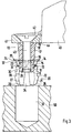
- the connecting pin 10 can be inserted into a fastening sleeve 20 are shown in detail in FIG. 2.
- the fastening sleeve 20 Like the connecting pin 10 can be made of a plastic part (for example an injection molded part).
- the fastening sleeve 20 has a lengthwise one Longitudinal slot 34 on.
- This longitudinal slot 34 extends over the entire height of the fastening sleeve 20 and is only in a partial area bridged by means of a clamping element 29.
- the tensioning element 29 is band-like formed and molded in one piece on the mounting sleeve.
- the fastening sleeve 20 still has at least one another longitudinal slot, so that 20 retaining springs 21 from the fastening sleeve are divided.
- the retaining springs 21 are toothed on their outside 22 provided.
- the toothing 22 runs at the lower end in FIG.
- a pass collar 23 is provided at the top of the mounting sleeve 20.
- the pass collar 23 runs accordingly the subdivision caused by the longitudinal slots 34, segment-like ring-shaped around the central longitudinal axis of the fastening sleeve 20.
- a support flange 24 is compared to the pass collar 23 enlarged in diameter.
- a spring element 25 closes the support flange 24 on. The spring element 25 protrudes over the support flange 24 and also runs like the fitting collar 23 and the central longitudinal axis of the fastening sleeve 20 around.
- the fastening sleeve 20 encloses a receptacle in which the connecting pin 10 can be inserted, as will be explained in more detail later.
- This receptacle is essentially formed by the retaining springs 21.
- Detent elements 26 are formed in the region of the free ends of the retaining springs 21. These locking elements 26 go, facing the receiving sleeve 20, into a flank 27, which is opposite the central longitudinal axis of the Mounting sleeve 20 is inclined.
- One is connected to the flank 28 Inner wall 28 which, via a shaped surface 30, increases in diameter Press surface 31 merges.
- the pressing surface 31 goes into a shoulder 32 about. There is a rugged transition between the pressing surface 31 and the shoulder 32 educated.
- Paragraph 32 concludes with an extension 33, which serves as an introduction aid for the Connecting pin 10 is used.
- the connecting pin 10 is in the Fastening sleeve 20 inserted.
- the deflection slope 11 slides on extension 33 and paragraph 32. Because of the geometry becomes the clear width of the longitudinal slot 34 in the area of the ramp 35 then downsized. Accordingly, the clear width of the Longitudinal slot 34 in the area of the support flange 24.
- the connecting pin 10 is now pushed further into the mounting sleeve 20, then the clamping element 29 transverse to the longitudinal extent of the fastening sleeve 20 stretched. The stretching is at least partially resilient. If the clamping element 29 comes into the region of the locking groove 15, so acts Spring elasticity such that the holding legs 21 in the area of the run-up slope 35 unfold the fastening sleeve 20.
- the connecting pin 10 Fastening part 40 for example a furniture fitting part.
- the Fastening part 40 has a projecting flange 41 which extends from a Bore 42 is penetrated.
- a fastening screw can be inserted into this bore 42 43 inserted and in the mounting receptacle 10.1 of the connecting pin 10 can be screwed.
- the fastening screw 43 sets the fastening part 40 so firmly on the connecting pin 10 that a lower Contact surface of the flange 41 on the facing end face of the end piece 19 of the connecting pin 10 rests.
- the fastening part 40, connecting pin 10 and fastening sleeve 20 existing unit can be attached to a workpiece 50.
- the workpiece 50 is provided with a bore, in the present case a blind bore 51.
- the fastening sleeve 20 in the Blind hole 51 used for Assembly of the fastening part 40.
- the run-up slopes 35 first slide of the fastening sleeve 20 at the hole of the blind hole 51.
- the holding legs 21 become radial deflected inwards.
- the positive one is lifted Connection (paragraph 32 - stop 14) between the connecting pin 10 and the mounting sleeve 20.
- the fastening sleeve 20 can now run continuously are inserted into the blind bore 51, the toothing 22 the fastening sleeve 20 is guided past the inner wall of the blind hole 51 becomes.
- the joining force required for this is determined, for example, by the Fastening part 40 initiated. This now prevents the connecting pin 10 is inserted into the mounting sleeve 20 before it is completely is inserted into the blind hole 51, the connecting pin 10 by means of the deflection slope 11 on the inclined shaped surface 30 of the fastening sleeve 20 held.
- the holding force generated on the molding surface 30 is larger than that for joining the fastening sleeve 20 into the blind hole 51 required joining force.
- the fastening sleeve 20 is completely inserted into the blind hole 51, so the Support flange 24 in the area around the bore entry of the blind bore 51 on the top of the workpiece 50. Now the joining force can be increased are so that the connecting pin 10 slides over the molding surface 30.
- the Holding leg 21 spread radially outwards. This will work out in detail causes the sliding surface 16 on the inner wall 28 of the mounting sleeve 20 accumulates.
- the teeth 22 can be a bit far into the surface penetrate the inner wall of the blind hole 51 and here barb-like claw. If the connecting pin 10 with its ramp slope 11 guided past the inner wall 28 of the fastening sleeve 20 it comes into engagement with the flank 27.
- the virtual pivot point is roughly the same as the first Tooth of the teeth 22 arranged.
- the outer bearing 12 of the connecting pin 10 has passed the locking elements 26 of the holding legs 21, snap these locking elements 26 into the locking groove 15.
- the end faces of the holding legs 21, which are approximately at right angles to the central longitudinal axis of the mounting sleeve 20 are on the steep locking flanks 13 of the connecting pin 10 on. This then prevents the connecting pin 10 are pulled out of the receptacle of the fastening sleeve 20 can, whereby a fixed connection of the fastening part 40 to the workpiece 50 becomes possible.
- the fastening sleeve 20 has one in the area of its fitting collar 23 Outside diameter, which is selected slightly larger than that Inner diameter of the blind bore 51.
- the Blind hole 51 a diameter of 8mm
- the collar 23 a Have a diameter of 8.1-8.2mm. Because of this massive
- the fitting collar 23 is designed radially after the fastening sleeve 20 has been joined deformed inside. This radial deformation causes the fitting collar 23 to the collar 18 of the connecting pin 10 is pressed. About these Pressing becomes a wobble-free bracing of the connecting pin 10 causes.
Landscapes
- Engineering & Computer Science (AREA)
- General Engineering & Computer Science (AREA)
- Mechanical Engineering (AREA)
- Snaps, Bayonet Connections, Set Pins, And Snap Rings (AREA)
- Insertion Pins And Rivets (AREA)
- Furniture Connections (AREA)
Applications Claiming Priority (4)
| Application Number | Priority Date | Filing Date | Title |
|---|---|---|---|
| DE19915119A DE19915119B4 (de) | 1999-04-01 | 1999-04-01 | Montageelement für den Möbelbau |
| DE19915119 | 1999-04-01 | ||
| DE19950745A DE19950745B4 (de) | 1999-04-01 | 1999-10-21 | Montageelement mit einem Verbindungszapfen und einer Befestigungshülse |
| DE19950745 | 1999-10-21 |
Publications (2)
| Publication Number | Publication Date |
|---|---|
| EP1041297A2 true EP1041297A2 (fr) | 2000-10-04 |
| EP1041297A3 EP1041297A3 (fr) | 2000-12-06 |
Family
ID=7903415
Family Applications (3)
| Application Number | Title | Priority Date | Filing Date |
|---|---|---|---|
| EP00106817A Withdrawn EP1041297A3 (fr) | 1999-04-01 | 2000-03-30 | Elément de montage |
| EP00106870A Expired - Lifetime EP1041299B1 (fr) | 1999-04-01 | 2000-03-30 | Elément de montage utilisé dans la fabrication de meubles |
| EP00106819A Expired - Lifetime EP1041298B1 (fr) | 1999-04-01 | 2000-03-30 | Elément de montage, utilisé notamment dans la fabrication de meubles |
Family Applications After (2)
| Application Number | Title | Priority Date | Filing Date |
|---|---|---|---|
| EP00106870A Expired - Lifetime EP1041299B1 (fr) | 1999-04-01 | 2000-03-30 | Elément de montage utilisé dans la fabrication de meubles |
| EP00106819A Expired - Lifetime EP1041298B1 (fr) | 1999-04-01 | 2000-03-30 | Elément de montage, utilisé notamment dans la fabrication de meubles |
Country Status (5)
| Country | Link |
|---|---|
| US (2) | US6406235B1 (fr) |
| EP (3) | EP1041297A3 (fr) |
| DE (4) | DE29918363U1 (fr) |
| DK (2) | DK1041299T3 (fr) |
| PL (3) | PL191752B1 (fr) |
Cited By (2)
| Publication number | Priority date | Publication date | Assignee | Title |
|---|---|---|---|---|
| WO2014072080A1 (fr) * | 2012-11-06 | 2014-05-15 | Inter Ikea Systems B.V. | Dispositif de fixation, système de fixation et ensemble meuble |
| US11629740B2 (en) * | 2017-11-15 | 2023-04-18 | Hangzhou Clean Dell Sanitary Ware Co., Ltd. | Connector and frame structure using same |
Families Citing this family (53)
| Publication number | Priority date | Publication date | Assignee | Title |
|---|---|---|---|---|
| DE10026886A1 (de) * | 2000-05-30 | 2001-12-06 | Fischer Artur Werke Gmbh | Spreizanker zur Befestigung an einem plattenförmigen Baustoff |
| US6517059B1 (en) * | 2000-07-17 | 2003-02-11 | Transnav, Inc. | Leaf spring insert and method for assembling a leaf spring |
| US7105119B2 (en) * | 2002-02-22 | 2006-09-12 | Newfrey Llc | Method of forming integrally molded clip |
| US6692176B1 (en) * | 2002-04-02 | 2004-02-17 | Asyst Technologies Llc | Ball socket with locking feature |
| US7033121B2 (en) * | 2002-09-30 | 2006-04-25 | Illinois Tool Works Inc | Water-tight grommet |
| DE10252673A1 (de) * | 2002-11-11 | 2004-06-17 | Dieter Glockner | Rohr-oder Vollprofilverbinder |
| DE10319413A1 (de) * | 2003-04-29 | 2004-11-18 | Schwinn Gmbh | Steckverbindung |
| JP2005150159A (ja) * | 2003-11-11 | 2005-06-09 | Toshiba Corp | 半導体装置、及び、半導体装置の製造方法 |
| US6991413B2 (en) * | 2004-01-14 | 2006-01-31 | Mccue Corporation | Drive anchor |
| JP2006138389A (ja) * | 2004-11-11 | 2006-06-01 | Tokai Rika Co Ltd | 締結構造 |
| US7306190B2 (en) * | 2004-12-10 | 2007-12-11 | Illinois Tool Works Inc | Fastener |
| FR2882797B1 (fr) * | 2005-03-02 | 2007-05-25 | Itw De France Soc Par Actions | Attache adaptee a etre fixee dans une cavite de contour predetermine |
| DE102005032699B4 (de) * | 2005-07-14 | 2007-08-23 | Itw Automotive Products Gmbh & Co. Kg | Befestigungsvorrichtung |
| FR2895467B1 (fr) * | 2005-12-23 | 2009-04-17 | Sidel Sas | Agencement pour l'assemblage de deux pieces par vissage par l'intermediaire d'un ensemble vis-ecrou |
| WO2007110863A2 (fr) * | 2006-03-24 | 2007-10-04 | Yosef Freedland | Dispositifs de fixation de paroi courbee |
| DE102006023548A1 (de) * | 2006-05-19 | 2007-11-22 | GM Global Technology Operations, Inc., Detroit | Verbindungselement für Bauteile eines Kraftfahrzeugs |
| US20080031702A1 (en) * | 2006-08-01 | 2008-02-07 | Ken-Ching Chen | Fast nail plug |
| US7413367B2 (en) * | 2006-10-17 | 2008-08-19 | Kenmark Industrial Co., Ltd. | Combinational commodity engaging unit |
| DE102007007663A1 (de) * | 2007-02-13 | 2008-08-14 | Zimmer, Günther | Hülse für Deckplattenklemmung und Bohrungsspreizung |
| DE102007011881A1 (de) * | 2007-03-13 | 2008-09-18 | Fischerwerke Gmbh & Co. Kg | Spreizdübel für zweischaliges Mauerwerk |
| DE202008002486U1 (de) | 2008-02-22 | 2008-07-31 | Kenmark Industrial Co. Ltd. | Plattenverbinder |
| NL1035101C1 (nl) | 2008-02-28 | 2008-03-21 | Hans Martijn Rosenboom | Bouwsysteem bestaande uit een vierhoekige buis met regelmatige uitsparingen aan de vier zijden waarmee - in combinatie met de binnenwerk blokjes - elk gewenst bouwwerk of meubelstuk kan worden geconstrueerd. |
| IT1391746B1 (it) * | 2008-07-29 | 2012-01-27 | Leonardo Srl | Gruppo reggipensile regolabile per l'ancoraggio a parete di un mobile pensile, con mezzi perfezionati di fissaggio alla spalla del mobile pensile |
| DE102009014678A1 (de) * | 2009-03-25 | 2010-09-30 | A.Raymond Et Cie | Spreizniet |
| JP5627940B2 (ja) * | 2010-07-01 | 2014-11-19 | 株式会社ニフコ | グロメット |
| DE102010051372B4 (de) | 2010-11-13 | 2012-05-24 | Amer Khodabandeh | Verbindungselement mit integrierter Schnappverbindung |
| DE102011017154A1 (de) * | 2011-04-15 | 2012-10-18 | A. Raymond Et Cie | Einsteckmutter |
| JP2012246963A (ja) * | 2011-05-26 | 2012-12-13 | Nifco Inc | グロメット |
| AT13085U1 (de) * | 2012-01-31 | 2013-05-15 | Florian Mang | Verbindungselement |
| DE102013208494A1 (de) | 2012-05-15 | 2013-11-21 | Confitt Gmbh | Vorrichtung zur werkzeuglosen Verbindung zweier Bauteile |
| DE202012102484U1 (de) * | 2012-07-05 | 2013-10-08 | Rehau Ag + Co | Verbindungsanordnung |
| DE202013003073U1 (de) * | 2013-04-04 | 2014-07-08 | Grass Gmbh | Befestigungselement für den Möbelbau |
| EP3063417B1 (fr) * | 2013-10-30 | 2018-09-19 | AS Connector | Dispositif de verrouillage |
| DE102014101119A1 (de) * | 2014-01-30 | 2015-07-30 | Illinois Tool Works Inc. | Befestigungsclip |
| CN103925264A (zh) * | 2014-03-25 | 2014-07-16 | 扬州市引江蓬帆制品有限公司 | 一种篷布与塔筒固定用堵塞 |
| FR3020099B1 (fr) * | 2014-04-16 | 2017-08-18 | Illinois Tool Works | Agrafe de fixation d'un panneau sur un support, procede de mise en oeuvre et equipement automobile |
| DE102014208533A1 (de) * | 2014-05-07 | 2015-11-12 | Keuro Besitz Gmbh & Co. Edv-Dienstleistungs Kg | Bandführung für ein Sägeband einer Sägemaschine |
| DE102015005937A1 (de) * | 2015-05-12 | 2016-11-17 | Günther Zimmer | Bolzenhaltevorrichtung und Verbindungssystem |
| DE102016007871A1 (de) * | 2016-06-29 | 2018-01-04 | Günther Zimmer | Selbstsichernde Bolzenhaltevorrichtung |
| FR3059738B1 (fr) * | 2016-12-01 | 2019-06-21 | Renault S.A.S. | Agrafe universelle |
| US20210008462A1 (en) * | 2018-01-04 | 2021-01-14 | KidKraft, Inc. | Play structure and play structure assembly methods |
| KR102295273B1 (ko) | 2018-07-06 | 2021-08-27 | 일리노이즈 툴 워크스 인코포레이티드 | 패스너 조립체 |
| GB2581532B (en) * | 2019-02-25 | 2021-07-07 | Mccue Int Inc | Flange anchor |
| EP3706265B1 (fr) * | 2019-03-07 | 2021-10-27 | ELDON Group | Procédé de montage d'un panneau sur une armoire électrique et une telle armoire |
| EP3770448A1 (fr) * | 2019-07-23 | 2021-01-27 | Lercher GmbH | Système de liaison pour la liaison mécanique de deux matériaux |
| US12146522B2 (en) * | 2020-12-08 | 2024-11-19 | The Boeing Company | Fastener insert for a composite sandwich panel, a panel assembly, and a method of fastening a component to a composite sandwich panel |
| JP2022108102A (ja) * | 2021-01-12 | 2022-07-25 | コクヨ株式会社 | リベット |
| JP7414034B2 (ja) * | 2021-03-29 | 2024-01-16 | 豊田合成株式会社 | クリップ構造 |
| GB2611069B (en) * | 2021-09-24 | 2024-01-17 | Ovvotech Innovations Ltd | A connector assembly |
| EP4417823A1 (fr) * | 2023-02-14 | 2024-08-21 | Fundación Tecnalia Research & Innovation | Connecteur pour fixer des panneaux de meuble |
| US20240337282A1 (en) * | 2023-04-06 | 2024-10-10 | Western Digital Technologies, Inc. | Rapid installation screw with radially expanding threads |
| DE102023124315A1 (de) * | 2023-09-08 | 2025-03-13 | Hettich-Heinze Gmbh & Co. Kg | Verbindungsbeschlag, Möbel und Verfahren zur Montage |
| WO2025136193A1 (fr) * | 2023-12-21 | 2025-06-26 | Inter Ikea Systems B.V. | Kit de pièces pour meuble |
Family Cites Families (22)
| Publication number | Priority date | Publication date | Assignee | Title |
|---|---|---|---|---|
| US2542144A (en) * | 1945-01-01 | 1951-02-20 | Shellmar Products Corp | Blind rivet |
| DE1400209B2 (de) * | 1960-09-08 | 1970-05-06 | Illinois Tool Works Inc., Chicago, 111. (V.St.A.) | Spreiznietartiges Befestigungselement |
| CA855914A (en) * | 1968-02-23 | 1970-11-17 | A. Mackenzie James | Releasable reusable expanding fastener |
| DE1922971A1 (de) * | 1969-05-06 | 1970-11-19 | Becher Dr Hans | Vorrichtung zur loesbaren Verbindung von Moebelbauteilen Kennwort: Moebelverbinder |
| US3765295A (en) * | 1971-08-18 | 1973-10-16 | Fastway Fasteners | Plastic drive pin anchor |
| DE2149502C3 (de) * | 1971-10-04 | 1981-09-24 | Karl Lautenschläger KG, Möbelbeschlagfabrik, 6107 Reinheim | Montageplatte für Möbelscharniere |
| US3739684A (en) * | 1971-11-12 | 1973-06-19 | J Vitkevich | Expansion hanger device |
| DE2815013A1 (de) * | 1977-04-15 | 1978-10-26 | Blum Gmbh Julius | Montageplatte |
| US4405272A (en) * | 1981-03-11 | 1983-09-20 | Phillips Plastics Corporation | Two-piece fastener with front shoulder |
| GB8630864D0 (en) * | 1986-12-24 | 1987-02-04 | Itw Ltd | Re-usable plastics drive rivets |
| JPH0310409Y2 (fr) * | 1987-01-30 | 1991-03-14 | ||
| GB8711360D0 (en) * | 1987-05-14 | 1987-06-17 | Tml Plastics Ltd | Fixing device |
| JPS6414912U (fr) * | 1987-07-16 | 1989-01-25 | ||
| DE9106455U1 (de) * | 1991-05-25 | 1992-09-17 | A. Raymond KG, 7850 Lörrach | Zweiteiliges Halteelement für Schutzleisten |
| DE4117114C1 (fr) * | 1991-05-25 | 1992-08-06 | A. Raymond Kg, 7850 Loerrach, De | |
| US5163795A (en) * | 1992-04-09 | 1992-11-17 | Illionis Tool Works, Inc. | Front mounted rivet with interlocked drive pin |
| DE4216220A1 (de) * | 1992-05-18 | 1993-11-25 | Boellhoff & Co | Schnellbefestigung für Griffe, Knöpfe o. dgl. Tafeln |
| DE9212217U1 (de) * | 1992-09-10 | 1992-11-19 | Pötzsch, Holger, 6100 Darmstadt | Spreizdübel |
| JPH0640428U (ja) * | 1992-10-29 | 1994-05-31 | 株式会社ニフコ | プッシュリベット |
| SE504104C2 (sv) * | 1994-02-25 | 1996-11-11 | Ericsson Telefon Ab L M | Fästelement för en täckplåt eller liknande |
| JP3290292B2 (ja) * | 1994-03-29 | 2002-06-10 | 株式会社ニフコ | 留め具 |
| JP3656689B2 (ja) * | 1996-08-30 | 2005-06-08 | 株式会社デンソー | センサ取付け用弾性部材、それを用いたセンサ取付け構造体およびそのセンサ取付け方法 |
-
1999
- 1999-04-01 DE DE29918363U patent/DE29918363U1/de not_active Expired - Lifetime
- 1999-04-01 DE DE19915119A patent/DE19915119B4/de not_active Expired - Fee Related
-
2000
- 2000-03-30 EP EP00106817A patent/EP1041297A3/fr not_active Withdrawn
- 2000-03-30 EP EP00106870A patent/EP1041299B1/fr not_active Expired - Lifetime
- 2000-03-30 PL PL339332A patent/PL191752B1/pl not_active IP Right Cessation
- 2000-03-30 DK DK00106870T patent/DK1041299T3/da active
- 2000-03-30 EP EP00106819A patent/EP1041298B1/fr not_active Expired - Lifetime
- 2000-03-30 PL PL00339331A patent/PL339331A1/xx not_active Application Discontinuation
- 2000-03-30 PL PL00339335A patent/PL339335A1/xx not_active IP Right Cessation
- 2000-03-30 DK DK00106819T patent/DK1041298T3/da active
- 2000-03-30 DE DE50004123T patent/DE50004123D1/de not_active Expired - Fee Related
- 2000-03-30 DE DE50008048T patent/DE50008048D1/de not_active Expired - Fee Related
- 2000-04-03 US US09/541,772 patent/US6406235B1/en not_active Expired - Fee Related
- 2000-04-03 US US09/541,295 patent/US6322305B1/en not_active Expired - Fee Related
Non-Patent Citations (1)
| Title |
|---|
| None |
Cited By (4)
| Publication number | Priority date | Publication date | Assignee | Title |
|---|---|---|---|---|
| WO2014072080A1 (fr) * | 2012-11-06 | 2014-05-15 | Inter Ikea Systems B.V. | Dispositif de fixation, système de fixation et ensemble meuble |
| US9771964B2 (en) | 2012-11-06 | 2017-09-26 | Inter Ikea Systems B.V. | Fastening device, fastening system and furniture assembly |
| RU2633259C2 (ru) * | 2012-11-06 | 2017-10-11 | Интер Икеа Системз Б.В. | Крепежное приспособление, крепежная система и блок мебели |
| US11629740B2 (en) * | 2017-11-15 | 2023-04-18 | Hangzhou Clean Dell Sanitary Ware Co., Ltd. | Connector and frame structure using same |
Also Published As
| Publication number | Publication date |
|---|---|
| EP1041299A2 (fr) | 2000-10-04 |
| DE19915119A1 (de) | 2000-10-12 |
| DE19915119B4 (de) | 2006-11-16 |
| PL339331A1 (en) | 2000-10-09 |
| US6406235B1 (en) | 2002-06-18 |
| EP1041298A3 (fr) | 2000-12-06 |
| EP1041298B1 (fr) | 2004-10-06 |
| DE50004123D1 (de) | 2003-11-27 |
| PL339332A1 (en) | 2000-10-09 |
| DK1041298T3 (da) | 2005-01-03 |
| PL191752B1 (pl) | 2006-06-30 |
| EP1041299B1 (fr) | 2003-10-22 |
| DK1041299T3 (da) | 2003-12-29 |
| DE50008048D1 (de) | 2004-11-11 |
| PL339335A1 (en) | 2000-10-09 |
| EP1041297A3 (fr) | 2000-12-06 |
| EP1041299A3 (fr) | 2000-12-06 |
| US6322305B1 (en) | 2001-11-27 |
| DE29918363U1 (de) | 2000-01-13 |
| EP1041298A2 (fr) | 2000-10-04 |
Similar Documents
| Publication | Publication Date | Title |
|---|---|---|
| EP1041297A2 (fr) | Elément de montage | |
| EP0176663B1 (fr) | Dispositif pour la jonction à haubanage de pièces situées à distance l'une de l'autre | |
| DE19505311C2 (de) | Befestigungsanordnung von Beschlägen, insbesondere Möbelbeschlägen an Möbelstücken | |
| EP1515054A1 (fr) | Dispositif de compensation de tolérance | |
| DE202005010873U1 (de) | Toleranzausgleichseinrichtung aus Kunststoff | |
| WO2020200776A1 (fr) | Élément de réglage en plusieurs parties pour un agencement de compensation de tolérances | |
| DE20020996U1 (de) | Verbindereinrichtung für Profile | |
| DE19949654B4 (de) | Toleranzausgleichselement | |
| EP2261519A2 (fr) | Vis destinée à la fixation d'un premier composant sur un second composant | |
| DE1801913B2 (de) | Anordnung von Beschlagteilen in Profilrahmen von Fenstern,Tueren od.dgl. | |
| DE102016106006B4 (de) | Vorrichtung zum Ausgleichen von Toleranzen | |
| EP2329747B1 (fr) | Dispositif de serrage pour corde pour rideaux | |
| WO2016041624A1 (fr) | Dispositif de fixation permettant de fixer un objet sanitaire | |
| DE102023205044A1 (de) | Vorrichtung zum Ausgleichen von Toleranzen zwischen zwei miteinander zu verbindenden Bauteilen | |
| EP0738374A1 (fr) | Ferrure d'assemblage | |
| DE102009051540A1 (de) | Selbstsichernde Einstelleinrichtung, Fahrzeuglenkung und Verfahren zum Einstellen eines Spiels eines Druckstück in einer Fahrzeuglenkung | |
| DE19950745A1 (de) | Montageelement | |
| EP3388691B1 (fr) | Connecteur face arrière | |
| EP3356688A1 (fr) | Cheville à bascule | |
| DE202010003368U1 (de) | Vorrichtung mit selbstätigem Ausgleich von fertigungs- oder montagebedingten Toleranzen zum Abstützen eines ersten Bauteils an einem zweiten Bauteil | |
| EP2108852B1 (fr) | Vis | |
| WO2008080703A2 (fr) | Ferrure d'assemblage pour assembler deux panneaux de meuble | |
| DE202006010207U1 (de) | Vorrichtung zur Anbringung an einem Profil | |
| DE102006001509B3 (de) | Scharnier für Türen oder Fenster sowie Verfahren zum Einsetzen eines für die Verstellung notwendigen Scharnierzapfens in einen Scharnierkopf bei einem Scharnier | |
| EP2530336B1 (fr) | Dispositif de soutien de composants |
Legal Events
| Date | Code | Title | Description |
|---|---|---|---|
| PUAI | Public reference made under article 153(3) epc to a published international application that has entered the european phase |
Free format text: ORIGINAL CODE: 0009012 |
|
| AK | Designated contracting states |
Kind code of ref document: A2 Designated state(s): DE DK |
|
| AX | Request for extension of the european patent |
Free format text: AL;LT;LV;MK;RO;SI |
|
| PUAL | Search report despatched |
Free format text: ORIGINAL CODE: 0009013 |
|
| AK | Designated contracting states |
Kind code of ref document: A3 Designated state(s): AT BE CH CY DE DK ES FI FR GB GR IE IT LI LU MC NL PT SE |
|
| AX | Request for extension of the european patent |
Free format text: AL;LT;LV;MK;RO;SI |
|
| RIC1 | Information provided on ipc code assigned before grant |
Free format text: 7F 16B 12/24 A, 7F 16B 19/10 B, 7F 16B 13/04 B |
|
| 17P | Request for examination filed |
Effective date: 20010606 |
|
| AKX | Designation fees paid |
Free format text: DE DK |
|
| GRAH | Despatch of communication of intention to grant a patent |
Free format text: ORIGINAL CODE: EPIDOS IGRA |
|
| GRAS | Grant fee paid |
Free format text: ORIGINAL CODE: EPIDOSNIGR3 |
|
| STAA | Information on the status of an ep patent application or granted ep patent |
Free format text: STATUS: THE APPLICATION IS DEEMED TO BE WITHDRAWN |
|
| 18D | Application deemed to be withdrawn |
Effective date: 20030717 |