EP1050509A1 - Système de nettoyage de gaz carbonique - Google Patents
Système de nettoyage de gaz carbonique Download PDFInfo
- Publication number
- EP1050509A1 EP1050509A1 EP00109643A EP00109643A EP1050509A1 EP 1050509 A1 EP1050509 A1 EP 1050509A1 EP 00109643 A EP00109643 A EP 00109643A EP 00109643 A EP00109643 A EP 00109643A EP 1050509 A1 EP1050509 A1 EP 1050509A1
- Authority
- EP
- European Patent Office
- Prior art keywords
- carbon dioxide
- absorption column
- water
- gas stream
- passing
- Prior art date
- Legal status (The legal status is an assumption and is not a legal conclusion. Google has not performed a legal analysis and makes no representation as to the accuracy of the status listed.)
- Granted
Links
- CURLTUGMZLYLDI-UHFFFAOYSA-N Carbon dioxide Chemical compound O=C=O CURLTUGMZLYLDI-UHFFFAOYSA-N 0.000 title claims abstract description 150
- 239000001569 carbon dioxide Substances 0.000 title claims abstract description 75
- 229910002092 carbon dioxide Inorganic materials 0.000 title claims abstract description 75
- 238000011084 recovery Methods 0.000 title claims abstract description 17
- 238000004140 cleaning Methods 0.000 title claims abstract description 8
- XLYOFNOQVPJJNP-UHFFFAOYSA-N water Substances O XLYOFNOQVPJJNP-UHFFFAOYSA-N 0.000 claims abstract description 73
- 239000000356 contaminant Substances 0.000 claims abstract description 54
- 238000010521 absorption reaction Methods 0.000 claims description 39
- 239000012530 fluid Substances 0.000 claims description 21
- 239000007788 liquid Substances 0.000 claims description 18
- OKTJSMMVPCPJKN-UHFFFAOYSA-N Carbon Chemical compound [C] OKTJSMMVPCPJKN-UHFFFAOYSA-N 0.000 claims description 15
- 229910052799 carbon Inorganic materials 0.000 claims description 13
- 238000000034 method Methods 0.000 claims description 10
- JEGUKCSWCFPDGT-UHFFFAOYSA-N h2o hydrate Chemical compound O.O JEGUKCSWCFPDGT-UHFFFAOYSA-N 0.000 claims description 5
- 238000004821 distillation Methods 0.000 claims description 3
- 238000001816 cooling Methods 0.000 claims description 2
- 239000007789 gas Substances 0.000 description 47
- 230000000630 rising effect Effects 0.000 description 4
- OKKJLVBELUTLKV-UHFFFAOYSA-N Methanol Chemical compound OC OKKJLVBELUTLKV-UHFFFAOYSA-N 0.000 description 3
- 239000000498 cooling water Substances 0.000 description 3
- 239000003507 refrigerant Substances 0.000 description 3
- XKRFYHLGVUSROY-UHFFFAOYSA-N Argon Chemical compound [Ar] XKRFYHLGVUSROY-UHFFFAOYSA-N 0.000 description 2
- IJGRMHOSHXDMSA-UHFFFAOYSA-N Atomic nitrogen Chemical compound N#N IJGRMHOSHXDMSA-UHFFFAOYSA-N 0.000 description 2
- LFQSCWFLJHTTHZ-UHFFFAOYSA-N Ethanol Chemical compound CCO LFQSCWFLJHTTHZ-UHFFFAOYSA-N 0.000 description 2
- VYPSYNLAJGMNEJ-UHFFFAOYSA-N Silicium dioxide Chemical compound O=[Si]=O VYPSYNLAJGMNEJ-UHFFFAOYSA-N 0.000 description 2
- QAOWNCQODCNURD-UHFFFAOYSA-N Sulfuric acid Chemical compound OS(O)(=O)=O QAOWNCQODCNURD-UHFFFAOYSA-N 0.000 description 2
- 238000001311 chemical methods and process Methods 0.000 description 2
- 238000004519 manufacturing process Methods 0.000 description 2
- VNWKTOKETHGBQD-UHFFFAOYSA-N methane Chemical compound C VNWKTOKETHGBQD-UHFFFAOYSA-N 0.000 description 2
- VUZPPFZMUPKLLV-UHFFFAOYSA-N methane;hydrate Chemical compound C.O VUZPPFZMUPKLLV-UHFFFAOYSA-N 0.000 description 2
- 238000012856 packing Methods 0.000 description 2
- 239000002699 waste material Substances 0.000 description 2
- UGFAIRIUMAVXCW-UHFFFAOYSA-N Carbon monoxide Chemical compound [O+]#[C-] UGFAIRIUMAVXCW-UHFFFAOYSA-N 0.000 description 1
- BVKZGUZCCUSVTD-UHFFFAOYSA-L Carbonate Chemical compound [O-]C([O-])=O BVKZGUZCCUSVTD-UHFFFAOYSA-L 0.000 description 1
- 239000000654 additive Substances 0.000 description 1
- 230000000996 additive effect Effects 0.000 description 1
- 229910052786 argon Inorganic materials 0.000 description 1
- 230000001174 ascending effect Effects 0.000 description 1
- QVGXLLKOCUKJST-UHFFFAOYSA-N atomic oxygen Chemical compound [O] QVGXLLKOCUKJST-UHFFFAOYSA-N 0.000 description 1
- 235000015173 baked goods and baking mixes Nutrition 0.000 description 1
- 235000013361 beverage Nutrition 0.000 description 1
- 239000006227 byproduct Substances 0.000 description 1
- 229910002091 carbon monoxide Inorganic materials 0.000 description 1
- 230000006835 compression Effects 0.000 description 1
- 238000007906 compression Methods 0.000 description 1
- 235000013365 dairy product Nutrition 0.000 description 1
- 239000003651 drinking water Substances 0.000 description 1
- 235000020188 drinking water Nutrition 0.000 description 1
- 230000007613 environmental effect Effects 0.000 description 1
- 235000012055 fruits and vegetables Nutrition 0.000 description 1
- 230000005484 gravity Effects 0.000 description 1
- 239000001257 hydrogen Substances 0.000 description 1
- 229910052739 hydrogen Inorganic materials 0.000 description 1
- 125000004435 hydrogen atom Chemical class [H]* 0.000 description 1
- 239000002440 industrial waste Substances 0.000 description 1
- 235000013372 meat Nutrition 0.000 description 1
- 229910052757 nitrogen Inorganic materials 0.000 description 1
- 239000001301 oxygen Substances 0.000 description 1
- 229910052760 oxygen Inorganic materials 0.000 description 1
- 239000000575 pesticide Substances 0.000 description 1
- 244000144977 poultry Species 0.000 description 1
- 235000013594 poultry meat Nutrition 0.000 description 1
- 235000014102 seafood Nutrition 0.000 description 1
- 239000000377 silicon dioxide Substances 0.000 description 1
- 241000894007 species Species 0.000 description 1
- 239000000126 substance Substances 0.000 description 1
- 235000013311 vegetables Nutrition 0.000 description 1
Images
Classifications
-
- C—CHEMISTRY; METALLURGY
- C01—INORGANIC CHEMISTRY
- C01B—NON-METALLIC ELEMENTS; COMPOUNDS THEREOF; METALLOIDS OR COMPOUNDS THEREOF NOT COVERED BY SUBCLASS C01C
- C01B32/00—Carbon; Compounds thereof
- C01B32/50—Carbon dioxide
-
- B—PERFORMING OPERATIONS; TRANSPORTING
- B01—PHYSICAL OR CHEMICAL PROCESSES OR APPARATUS IN GENERAL
- B01D—SEPARATION
- B01D53/00—Separation of gases or vapours; Recovering vapours of volatile solvents from gases; Chemical or biological purification of waste gases, e.g. engine exhaust gases, smoke, fumes, flue gases, aerosols
- B01D53/14—Separation of gases or vapours; Recovering vapours of volatile solvents from gases; Chemical or biological purification of waste gases, e.g. engine exhaust gases, smoke, fumes, flue gases, aerosols by absorption
-
- Y—GENERAL TAGGING OF NEW TECHNOLOGICAL DEVELOPMENTS; GENERAL TAGGING OF CROSS-SECTIONAL TECHNOLOGIES SPANNING OVER SEVERAL SECTIONS OF THE IPC; TECHNICAL SUBJECTS COVERED BY FORMER USPC CROSS-REFERENCE ART COLLECTIONS [XRACs] AND DIGESTS
- Y02—TECHNOLOGIES OR APPLICATIONS FOR MITIGATION OR ADAPTATION AGAINST CLIMATE CHANGE
- Y02C—CAPTURE, STORAGE, SEQUESTRATION OR DISPOSAL OF GREENHOUSE GASES [GHG]
- Y02C20/00—Capture or disposal of greenhouse gases
- Y02C20/40—Capture or disposal of greenhouse gases of CO2
Definitions
- This invention relates generally to the production of carbon dioxide.
- Carbon dioxide has a large number of uses. For example, carbon dioxide is used to carbonate beverages, to chill, freeze and package seafood, meat, poultry, baked goods, fruits and vegetables, and to extend the shelf-life of dairy products. It is an important environmental component in industrial waste and process water treatment as a replacement for sulfuric acid to control pH levels. Other uses included drinking water treatment, an environmentally-friendly pesticide and an atmosphere additive in greenhouses to improve the growth of vegetables.
- carbon dioxide is produced by purifying a waste stream which is a by-product of an organic or inorganic chemical process.
- the waste stream comprises carbon dioxide and water soluble contaminants from the chemical process, and the carbon dioxide must be cleaned of these contaminants prior to recovery. The cleaning results in the loss of some of the carbon dioxide.
- a method for recovering carbon dioxide from a gas stream comprising:
- Another aspect of this invention is:
- Apparatus for cleaning carbon dioxide comprising:
- the term "absorption column” means a vessel wherein a gas and liquid are contacted to transfer one or more components from the gas to the liquid. Typically, the contact will be with upward flow of gas and downward flow of liquid on mass transfer elements such as random or structured packing or trays.
- phase separator means a vessel wherein a two phase feed can be separated into its separate gas and liquid fractions.
- the phase separator will be a vessel with sufficient cross-sectional area so that the gas and liquid will be disengaged by gravity, with liquid removal at the bottom and vapor removal at the top of the vessel.
- water soluble contaminants means any gaseous contaminant that is appreciably soluable in water such as methanol or ethanol.
- upper portion and lower portion mean those sections of a column respectively above and below the mid point of the column.
- directly heat exchange means the bringing of two fluids into heat exchange relation without any physical contact or intermixing of the fluids with each other.
- cooling means an indirect heat exchanger wherein a compressed gas stream comprising water vapor is cooled and at least some of the water vapor is condensed.
- light contaminants means one or more species having a vapor pressure greater than that of carbon dioxide.
- Examples of light contaminants include nitrogen, oxygen, argon, hydrogen, carbon monoxide and methane.
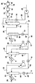
- gas stream 20 comprises generally from about 90 to 99 mole percent carbon dioxide and up to about 1.0 mole percent water soluble contaminants along with water vapor.
- gas stream 20 also comprises light contaminants, typically in a concentration up to about 5 mole percent.
- Crude carbon dioxide gas stream 20 is cooled in heat exchanger 1 by indirect heat exchange with a suitable fluid such as forced air, cooling water or a liquid refrigerant, and then passed in stream 21 into phase separator 2 wherein it is separated into a gas portion and a liquid water portion.
- the gas portion is passed as feed or gas stream 22 to compressor 5 wherein it is compressed to a pressure generally within the range of from about 4 to 6 atmospheres to produce compressed gas stream 23.
- Compressed gas stream 23 comprising carbon dioxide, water vapor and water soluble contaminants as well as light contaminants is cooled in aftercooler 6 by indirect heat exchange with a suitable fluid such as forced air, cooling water or a liquid refrigerant.
- a suitable fluid such as forced air, cooling water or a liquid refrigerant.
- the resulting two-phase fluid is passed in stream 24 into phase separator 7 wherein it is separated into a carbon dioxide-richer gas stream 25, which also contains water soluble contaminants and light contaminants, and also into remaining liquid which is primarily water.
- Carbon dioxide-richer gas stream 25 is passed to compressor 9 wherein it is further compressed to a pressure generally within the range of from about 15 to 25 atmospheres to produce further compressed gas stream 26.
- Further compressed gas stream 26 comprising carbon dioxide and water soluble contaminants as well as light contaminants is cooled in aftercooler 10 by indirect heat exchange with a suitable fluid such as forced air, cooling water or a liquid refrigerant.
- the resulting two-phase fluid is passed in stream 27 into phase separator 11 wherein it is separated into further carbon dioxide-richer gas stream 28, which also contains water soluble contaminants and light contaminants, and also into further remaining liquid which is primarily water.
- Carbon dioxide-richer gas stream 28 is passed into the lower portion of absorption column 13 and flows up the absorption column.
- Water 29 is pressurized by passage through mechanical pump 15 to a pressure sufficient for introduction into the top of absorption column 13, generally within the range of from 250 to 370 pounds per square inch absolute (psia).
- Pressurized water 30 is directed through flow/pressure control valve 14 and then as stream 31 is passed into the upper portion of absorption column 13 and down the absorption column.
- Absorption column 13 is a vertically oriented vessel generally having random or structured packing as the column internals, i.e. vapor/liquid contact elements, although the column internals may also comprise trays.
- the column internals serve to facilitate contact between the descending water and the rising gas.
- water soluble contaminants are passed from the rising gas into solution within the descending water so that the descending water is progressively enriched in the water soluble contaminants and the rising gas is progressively depleted of the water soluble contaminants.
- some carbon dioxide from the rising gas is absorbed into the downflowing water. This results in the production of cleaned carbon dioxide at the top of column 13 and contaminant-bearing water which also contains some carbon dioxide gas absorbed therein at the bottom of column 13.
- the cleaned carbon dioxide is withdrawn from the upper portion of column 13 in stream 32 and, if desired, may be recovered directly.
- the embodiment of the invention illustrated in the Figure is a particularly preferred embodiment wherein the cleaned carbon dioxide undergoes additional processing steps prior to recovery.
- gas stream 32 is further cleaned of any remaining water soluble contaminants as well as of water vapor picked up in the countercurrent upflow within column 13 by passage through adsorber 16 which may comprise one or more beds of activated carbon and/or silica.
- adsorber 16 may comprise one or more beds of activated carbon and/or silica.
- the resulting further cleaned and dried gas 33 may be passed from adsorber 16 to refrigerative means 18 wherein it is cooled and any remaining water is condensed and removed.
- the feed gas also contains light contaminants.
- the cleaned and dried carbon dioxide gas stream may be passed as stream 34 into a distillation column, illustrated in representational fashion in the Figure as element 19, wherein it is separated by rectification into purified carbon dioxide 35 and light contaminant top vapor 36.
- the purified carbon dioxide 35 is recovered as a fluid comprising from about 99.9 to 99.999 mole percent carbon dioxide.
- the contaminant-bearing water is withdrawn from the lower portion of column 13 in stream 37. Further remaining liquid is withdrawn from phase separator 11 in stream 38, passed through valve 12 and as stream 39 combined with stream 37 to form combined stream 40.
- Stream 40 is passed through pressure reducing device 17 which in the embodiment illustrated in the Figure is an expansion valve. Pressure reducing device 17 could be other pressure reducing means such as a turboexpander. As contaminant-bearing water stream 40 passes through pressure reducing device 17, its pressure is reduced, generally to be within the range of from 4 to 6 atmospheres, and in the process carbon dioxide gas, which had been absorbed into the contaminant-bearing water, is released resulting in the generation of two phase stream 41 comprising contaminant-bearing water and gaseous carbon dioxide.
- Two-phase stream 41 is passed into phase separator 7 wherein the released gaseous carbon dioxide in stream 41 is passed into the carbon dioxide-richer stream for eventual passage into absorption column 13 and ultimately for recovery.
- the released gaseous carbon dioxide in stream 41 is passed into the carbon dioxide-richer stream for eventual passage into absorption column 13 and ultimately for recovery.
- the contaminant-bearing water combines with remaining liquid in phase separator 7 and is passed out from phase separator 7 in stream 42 and through pressure reducing device 8, such as an expansion valve or turboexpander, wherein its pressure is reduced generally to be within the range of from 1 to 2 atmospheres.
- pressure reducing device 8 such as an expansion valve or turboexpander
- two phase stream 43 comprising contaminant-bearing water and gaseous carbon dioxide.
- Two phase stream 43 is passed into phase separator 2 wherein the released gaseous carbon dioxide in stream 43 is passed into the gas forming gas stream 22 for eventual passage into absorption column 13 and ultimate recovery, thus further improving the carbon dioxide recovery.
- the residual contaminant-bearing water is combined with the liquid portion of stream 21 in phase separator 2, withdrawn from phase separator 2 in stream 44, passed through valve 33 and as stream 45 passed to capture means, e.g. chemical sewer, 4 for ultimate disposal.
- recovery of carbon dioxide from any given crude carbon dioxide feed stream can be increased by from 0.5 to 1.0 percent over conventional systems which clean a crude carbon dioxide gas stream of water soluble contaminants.
Landscapes
- Chemical & Material Sciences (AREA)
- Organic Chemistry (AREA)
- Chemical Kinetics & Catalysis (AREA)
- Inorganic Chemistry (AREA)
- Engineering & Computer Science (AREA)
- Analytical Chemistry (AREA)
- General Chemical & Material Sciences (AREA)
- Oil, Petroleum & Natural Gas (AREA)
- Carbon And Carbon Compounds (AREA)
- Gas Separation By Absorption (AREA)
- Treating Waste Gases (AREA)
Applications Claiming Priority (2)
| Application Number | Priority Date | Filing Date | Title |
|---|---|---|---|
| US306816 | 1994-09-15 | ||
| US09/306,816 US6210467B1 (en) | 1999-05-07 | 1999-05-07 | Carbon dioxide cleaning system with improved recovery |
Publications (2)
| Publication Number | Publication Date |
|---|---|
| EP1050509A1 true EP1050509A1 (fr) | 2000-11-08 |
| EP1050509B1 EP1050509B1 (fr) | 2003-08-06 |
Family
ID=23186987
Family Applications (1)
| Application Number | Title | Priority Date | Filing Date |
|---|---|---|---|
| EP00109643A Expired - Lifetime EP1050509B1 (fr) | 1999-05-07 | 2000-05-05 | Système de nettoyage de gaz carbonique |
Country Status (11)
| Country | Link |
|---|---|
| US (1) | US6210467B1 (fr) |
| EP (1) | EP1050509B1 (fr) |
| JP (1) | JP2000335912A (fr) |
| KR (1) | KR100475474B1 (fr) |
| CN (1) | CN1152732C (fr) |
| AR (1) | AR023861A1 (fr) |
| BR (1) | BR0002293A (fr) |
| CA (1) | CA2307694C (fr) |
| DE (1) | DE60004283T2 (fr) |
| ES (1) | ES2199721T3 (fr) |
| MX (1) | MXPA00004386A (fr) |
Cited By (3)
| Publication number | Priority date | Publication date | Assignee | Title |
|---|---|---|---|---|
| US7927572B2 (en) | 2008-09-26 | 2011-04-19 | Praxair Technology, Inc. | Purifying carbon dioxide and producing acid |
| US8475566B2 (en) | 2004-10-08 | 2013-07-02 | Union Engineering A/S | Method for recovery of carbon dioxide from a gas |
| US8580206B2 (en) | 2005-11-28 | 2013-11-12 | Air Products And Chemicals, Inc. | Purification of carbon dioxide |
Families Citing this family (48)
| Publication number | Priority date | Publication date | Assignee | Title |
|---|---|---|---|---|
| JP2005506694A (ja) * | 2001-10-17 | 2005-03-03 | プラクスエア・テクノロジー・インコーポレイテッド | 中央二酸化炭素精製器 |
| US20050006310A1 (en) * | 2003-07-10 | 2005-01-13 | Rajat Agrawal | Purification and recovery of fluids in processing applications |
| MX2007001367A (es) * | 2004-08-06 | 2007-04-10 | Eig Inc | Ultra limpieza de gases de combustion, incluyendo la eliminacion de co2. |
| JP4515903B2 (ja) * | 2004-12-28 | 2010-08-04 | 日本インスツルメンツ株式会社 | ガス中水銀の測定装置の自動洗浄 |
| US8087926B2 (en) * | 2005-12-28 | 2012-01-03 | Jupiter Oxygen Corporation | Oxy-fuel combustion with integrated pollution control |
| JP5512281B2 (ja) * | 2007-01-17 | 2014-06-04 | ユニオン、エンジニアリング、アクティーゼルスカブ | 高純度二酸化炭素の回収方法 |
| US8088196B2 (en) * | 2007-01-23 | 2012-01-03 | Air Products And Chemicals, Inc. | Purification of carbon dioxide |
| US7850763B2 (en) * | 2007-01-23 | 2010-12-14 | Air Products And Chemicals, Inc. | Purification of carbon dioxide |
| US7819951B2 (en) * | 2007-01-23 | 2010-10-26 | Air Products And Chemicals, Inc. | Purification of carbon dioxide |
| US9512351B2 (en) | 2007-05-10 | 2016-12-06 | Halliburton Energy Services, Inc. | Well treatment fluids and methods utilizing nano-particles |
| US7784542B2 (en) * | 2007-05-10 | 2010-08-31 | Halliburton Energy Services, Inc. | Cement compositions comprising latex and a nano-particle and associated methods |
| CN101125651B (zh) * | 2007-06-05 | 2010-09-08 | 浙江大学 | 从甲酸钙生产工艺的尾气中回收二氧化碳的方法 |
| US8182577B2 (en) * | 2007-10-22 | 2012-05-22 | Alstom Technology Ltd | Multi-stage CO2 removal system and method for processing a flue gas stream |
| US7862788B2 (en) * | 2007-12-05 | 2011-01-04 | Alstom Technology Ltd | Promoter enhanced chilled ammonia based system and method for removal of CO2 from flue gas stream |
| GB0800792D0 (en) * | 2008-01-16 | 2008-02-27 | Lancer Gb Llp | Liquid dispensing system |
| FR2926876B1 (fr) * | 2008-01-28 | 2010-03-05 | Air Liquide | Procede de combustion de combustibles carbones avec filtration des fumees de combustion avant compression. |
| US20090282977A1 (en) * | 2008-05-14 | 2009-11-19 | Alstom Technology Ltd | Gas purification system having provisions for co2 injection of wash water |
| NZ590827A (en) * | 2008-07-29 | 2011-12-22 | Union Engineering As | A method for recovery of high purity carbon dioxide |
| US7846240B2 (en) | 2008-10-02 | 2010-12-07 | Alstom Technology Ltd | Chilled ammonia based CO2 capture system with water wash system |
| US8404027B2 (en) * | 2008-11-04 | 2013-03-26 | Alstom Technology Ltd | Reabsorber for ammonia stripper offgas |
| US8292989B2 (en) * | 2009-10-30 | 2012-10-23 | Alstom Technology Ltd | Gas stream processing |
| JP2012525974A (ja) * | 2009-05-08 | 2012-10-25 | アルストム テクノロジー リミテッド | 二酸化炭素捕捉及び燃料処理のための圧縮プロセスからの熱回収 |
| FR2949072B1 (fr) * | 2009-08-13 | 2017-03-31 | Ass Pour La Rech Et Le Dev Des Methodes Et Processus Industriels-Armines | Procede et systeme ameliores pour l'extraction d'une substance par antisublimation et fusion |
| US8784761B2 (en) * | 2009-11-20 | 2014-07-22 | Alstom Technology Ltd | Single absorber vessel to capture CO2 |
| US8790605B2 (en) * | 2009-09-15 | 2014-07-29 | Alstom Technology Ltd | Method for removal of carbon dioxide from a process gas |
| US8309047B2 (en) | 2009-09-15 | 2012-11-13 | Alstom Technology Ltd | Method and system for removal of carbon dioxide from a process gas |
| US8518156B2 (en) * | 2009-09-21 | 2013-08-27 | Alstom Technology Ltd | Method and system for regenerating a solution used in a wash vessel |
| EP2322265A1 (fr) | 2009-11-12 | 2011-05-18 | Alstom Technology Ltd | Système de traitement de gaz de fumée |
| US8293200B2 (en) * | 2009-12-17 | 2012-10-23 | Alstom Technology Ltd | Desulfurization of, and removal of carbon dioxide from, gas mixtures |
| US20110146489A1 (en) * | 2009-12-17 | 2011-06-23 | Alstom Technology Ltd | Ammonia removal, following removal of co2, from a gas stream |
| EP2383522B1 (fr) | 2010-04-28 | 2016-11-02 | General Electric Technology GmbH | Intégration thermique d'une capture de dioxyde de carbone et unité de compression dotée d'une installation à vapeur ou à cycle combiné |
| FR2961270B1 (fr) * | 2010-06-11 | 2017-07-28 | Air Liquide | Procede et appareil de sechage et de compression d'un flux riche en co2 |
| US8728209B2 (en) | 2010-09-13 | 2014-05-20 | Alstom Technology Ltd | Method and system for reducing energy requirements of a CO2 capture system |
| US8623307B2 (en) | 2010-09-14 | 2014-01-07 | Alstom Technology Ltd. | Process gas treatment system |
| US8329128B2 (en) | 2011-02-01 | 2012-12-11 | Alstom Technology Ltd | Gas treatment process and system |
| US9028784B2 (en) | 2011-02-15 | 2015-05-12 | Alstom Technology Ltd | Process and system for cleaning a gas stream |
| DE102011102923A1 (de) * | 2011-05-31 | 2012-12-06 | Ingenieurbüro Buse Gmbh | Anlage und Verfahren zur Aufbereitung von Biogas |
| US20130081409A1 (en) * | 2011-09-30 | 2013-04-04 | General Electric Company | Methods and systems for co2 condensation |
| US9162177B2 (en) | 2012-01-25 | 2015-10-20 | Alstom Technology Ltd | Ammonia capturing by CO2 product liquid in water wash liquid |
| US8864879B2 (en) | 2012-03-30 | 2014-10-21 | Jalal Askander | System for recovery of ammonia from lean solution in a chilled ammonia process utilizing residual flue gas |
| CN102853634A (zh) * | 2012-08-14 | 2013-01-02 | 中国石油化工股份有限公司 | 一种二氧化碳回收方法 |
| US9447996B2 (en) | 2013-01-15 | 2016-09-20 | General Electric Technology Gmbh | Carbon dioxide removal system using absorption refrigeration |
| CN103363537B (zh) * | 2013-06-03 | 2014-08-27 | 华中科技大学 | 一种富氧燃烧烟气净化装置 |
| US8986640B1 (en) | 2014-01-07 | 2015-03-24 | Alstom Technology Ltd | System and method for recovering ammonia from a chilled ammonia process |
| JP2016215174A (ja) * | 2015-05-26 | 2016-12-22 | 株式会社東芝 | 二酸化炭素回収システムおよび二酸化炭素回収システムの運転方法 |
| CN105233521A (zh) * | 2015-10-26 | 2016-01-13 | 成都华气厚普机电设备股份有限公司 | Lng燃烧尾气co2捕捉系统 |
| EP3192984B1 (fr) * | 2016-01-13 | 2020-06-17 | General Electric Technology GmbH | Procédé pour faire fonctionner une centrale thermique à vapeur et centrale thermique à vapeur pour la mise en oeuvre dudit procédé |
| KR102444842B1 (ko) * | 2020-07-29 | 2022-09-21 | 디아이지에어가스 주식회사 | 초고순도 전자급 이산화탄소 생산 장치 |
Citations (5)
| Publication number | Priority date | Publication date | Assignee | Title |
|---|---|---|---|---|
| FR1287759A (fr) * | 1960-04-14 | 1962-03-16 | Uhde Gmbh Friedrich | Procédé de récupération de gaz carbonique de très grande pureté |
| EP0194795A2 (fr) * | 1985-03-05 | 1986-09-17 | Kins Developments Limited | Epuration de dioxyde de carbone pour son utilisation dans la brasserie |
| WO1992007933A1 (fr) * | 1990-10-24 | 1992-05-14 | Heineken Technical Services B.V. | Procede de recuperation de gaz carbonique sensiblement pur a partir d'un biogaz |
| EP0646756A1 (fr) * | 1993-09-24 | 1995-04-05 | Haffmans B.V. | Procédé de la préparation de gaz de dioxyde de carbone pur et dispositif utilisé pour la mise en oeuvre |
| DE19755213A1 (de) * | 1997-01-30 | 1998-08-06 | Tecno Project Ind Srl | Verfahren zur Reinigung von Kohlensäure, die aus geeigneten Industrieverfahren, wie beispielsweise Gärungsprozessen, gewonnen wurde und angewendete Reinigungseinrichtungen |
Family Cites Families (9)
| Publication number | Priority date | Publication date | Assignee | Title |
|---|---|---|---|---|
| US3593491A (en) * | 1969-05-21 | 1971-07-20 | Fluor Corp | Ammonia plant carbon dioxide absorption and compression |
| US3770622A (en) * | 1970-12-28 | 1973-11-06 | Fluor Corp | Treatment of wet natural gas mixtures to recover liquid hydrocarbons |
| US4080424A (en) | 1976-02-11 | 1978-03-21 | Institute Of Gas Technology | Process for acid gas removal from gaseous mixtures |
| US4184855A (en) | 1977-12-29 | 1980-01-22 | Union Carbide Corporation | Process for CO2 removal |
| US4252548A (en) * | 1979-01-02 | 1981-02-24 | Kryos Energy Inc. | Carbon dioxide removal from methane-containing gases |
| DE2909335A1 (de) * | 1979-03-09 | 1980-09-18 | Linde Ag | Verfahren und vorrichtung zur zerlegung von erdgas |
| DE3314381A1 (de) | 1983-04-21 | 1984-10-25 | Linde Ag, 6200 Wiesbaden | Verfahren zum abtrennen von co(pfeil abwaerts)2(pfeil abwaerts) aus rauchgasen |
| US4548620A (en) * | 1984-02-07 | 1985-10-22 | Key Engineering, Inc. | Process for treating natural gas |
| US4589896A (en) * | 1985-01-28 | 1986-05-20 | Air Products And Chemicals, Inc. | Process for separating CO2 and H2 S from hydrocarbons |
-
1999
- 1999-05-07 US US09/306,816 patent/US6210467B1/en not_active Expired - Fee Related
-
2000
- 2000-04-30 CN CNB001082477A patent/CN1152732C/zh not_active Expired - Fee Related
- 2000-05-02 JP JP2000133271A patent/JP2000335912A/ja not_active Withdrawn
- 2000-05-04 KR KR10-2000-0023947A patent/KR100475474B1/ko not_active Expired - Fee Related
- 2000-05-04 MX MXPA00004386A patent/MXPA00004386A/es unknown
- 2000-05-05 CA CA002307694A patent/CA2307694C/fr not_active Expired - Fee Related
- 2000-05-05 ES ES00109643T patent/ES2199721T3/es not_active Expired - Lifetime
- 2000-05-05 DE DE60004283T patent/DE60004283T2/de not_active Expired - Fee Related
- 2000-05-05 EP EP00109643A patent/EP1050509B1/fr not_active Expired - Lifetime
- 2000-05-05 BR BR0002293-4A patent/BR0002293A/pt not_active Application Discontinuation
- 2000-05-05 AR ARP000102170A patent/AR023861A1/es unknown
Patent Citations (5)
| Publication number | Priority date | Publication date | Assignee | Title |
|---|---|---|---|---|
| FR1287759A (fr) * | 1960-04-14 | 1962-03-16 | Uhde Gmbh Friedrich | Procédé de récupération de gaz carbonique de très grande pureté |
| EP0194795A2 (fr) * | 1985-03-05 | 1986-09-17 | Kins Developments Limited | Epuration de dioxyde de carbone pour son utilisation dans la brasserie |
| WO1992007933A1 (fr) * | 1990-10-24 | 1992-05-14 | Heineken Technical Services B.V. | Procede de recuperation de gaz carbonique sensiblement pur a partir d'un biogaz |
| EP0646756A1 (fr) * | 1993-09-24 | 1995-04-05 | Haffmans B.V. | Procédé de la préparation de gaz de dioxyde de carbone pur et dispositif utilisé pour la mise en oeuvre |
| DE19755213A1 (de) * | 1997-01-30 | 1998-08-06 | Tecno Project Ind Srl | Verfahren zur Reinigung von Kohlensäure, die aus geeigneten Industrieverfahren, wie beispielsweise Gärungsprozessen, gewonnen wurde und angewendete Reinigungseinrichtungen |
Non-Patent Citations (2)
| Title |
|---|
| CHEMICAL ABSTRACTS, vol. 112, no. 20, 14 May 1990, Columbus, Ohio, US; abstract no. 182331v, ZHOU, GUIQING: "Recovery of carbon dioxide from ethanol manufacture by fermentation" XP000152539 * |
| SHANGHAI HUANJING KEXUE, vol. 8, no. 6, 1989, pages 24 - 35 * |
Cited By (4)
| Publication number | Priority date | Publication date | Assignee | Title |
|---|---|---|---|---|
| US8475566B2 (en) | 2004-10-08 | 2013-07-02 | Union Engineering A/S | Method for recovery of carbon dioxide from a gas |
| US8580206B2 (en) | 2005-11-28 | 2013-11-12 | Air Products And Chemicals, Inc. | Purification of carbon dioxide |
| US7927572B2 (en) | 2008-09-26 | 2011-04-19 | Praxair Technology, Inc. | Purifying carbon dioxide and producing acid |
| US7927573B2 (en) | 2008-09-26 | 2011-04-19 | Praxair Technology, Inc. | Multi-stage process for purifying carbon dioxide and producing acid |
Also Published As
| Publication number | Publication date |
|---|---|
| US6210467B1 (en) | 2001-04-03 |
| DE60004283T2 (de) | 2004-06-17 |
| CN1152732C (zh) | 2004-06-09 |
| BR0002293A (pt) | 2001-01-23 |
| KR20010049328A (ko) | 2001-06-15 |
| KR100475474B1 (ko) | 2005-03-10 |
| JP2000335912A (ja) | 2000-12-05 |
| EP1050509B1 (fr) | 2003-08-06 |
| DE60004283D1 (de) | 2003-09-11 |
| CN1273139A (zh) | 2000-11-15 |
| CA2307694C (fr) | 2003-03-25 |
| CA2307694A1 (fr) | 2000-11-07 |
| ES2199721T3 (es) | 2004-03-01 |
| AR023861A1 (es) | 2002-09-04 |
| MXPA00004386A (es) | 2002-03-08 |
Similar Documents
| Publication | Publication Date | Title |
|---|---|---|
| US6210467B1 (en) | Carbon dioxide cleaning system with improved recovery | |
| EP0965564B1 (fr) | Système de production de dioxyde de carbone avec un condensateur intégral du gaz d'évent | |
| EP1680208B1 (fr) | Procede et systeme de distillation a membrane pour extraire le co sb 2 /sb de gaz d'hydrocarbures | |
| EP1026463B1 (fr) | Procédé de production de dioxyde de carbone | |
| JP2989516B2 (ja) | 昇圧窒素を製造するための極低温精留方法及びその装置 | |
| US4902321A (en) | Cryogenic rectification process for producing ultra high purity nitrogen | |
| US5100446A (en) | Crude neon production system | |
| US5197296A (en) | Cryogenic rectification system for producing elevated pressure product | |
| EP3067315B1 (fr) | Procédé de séparation de gaz léger et système | |
| EP0606081A1 (fr) | Système de purification utilisant la chaleur à compression | |
| JPH08178521A (ja) | 高純度窒素の製造方法及び製造装置 | |
| CN1123752C (zh) | 用于生产高压氧的低温精馏系统 | |
| HU209266B (en) | Process and equipment for generating nitrogen | |
| KR100319440B1 (ko) | 저순도산소및고순도질소제조방법및장치 | |
| JP2680082B2 (ja) | 超高純度酸素製造方法 | |
| US20020095951A1 (en) | Method and apparatuses for the production of synthetic air products and related gases | |
| CN106403500A (zh) | 基于膨胀制冷提纯一氧化碳的方法及用于该方法的装置 | |
| JPH0579754A (ja) | 高純度窒素の製造装置 | |
| JPH0219398B2 (fr) | ||
| CN110950339A (zh) | 一种高纯二氧化碳的制备方法及制备装置 | |
| JPH0317488A (ja) | 高純度酸素の製造方法及びその装置 |
Legal Events
| Date | Code | Title | Description |
|---|---|---|---|
| PUAI | Public reference made under article 153(3) epc to a published international application that has entered the european phase |
Free format text: ORIGINAL CODE: 0009012 |
|
| AK | Designated contracting states |
Kind code of ref document: A1 Designated state(s): DE ES FR GB IT |
|
| AX | Request for extension of the european patent |
Free format text: AL;LT;LV;MK;RO;SI |
|
| 17P | Request for examination filed |
Effective date: 20001120 |
|
| AKX | Designation fees paid |
Free format text: DE ES FR GB IT |
|
| 17Q | First examination report despatched |
Effective date: 20011113 |
|
| GRAH | Despatch of communication of intention to grant a patent |
Free format text: ORIGINAL CODE: EPIDOS IGRA |
|
| GRAH | Despatch of communication of intention to grant a patent |
Free format text: ORIGINAL CODE: EPIDOS IGRA |
|
| GRAA | (expected) grant |
Free format text: ORIGINAL CODE: 0009210 |
|
| AK | Designated contracting states |
Designated state(s): DE ES FR GB IT |
|
| REG | Reference to a national code |
Ref country code: GB Ref legal event code: FG4D |
|
| REF | Corresponds to: |
Ref document number: 60004283 Country of ref document: DE Date of ref document: 20030911 Kind code of ref document: P |
|
| REG | Reference to a national code |
Ref country code: ES Ref legal event code: FG2A Ref document number: 2199721 Country of ref document: ES Kind code of ref document: T3 |
|
| ET | Fr: translation filed | ||
| PLBE | No opposition filed within time limit |
Free format text: ORIGINAL CODE: 0009261 |
|
| STAA | Information on the status of an ep patent application or granted ep patent |
Free format text: STATUS: NO OPPOSITION FILED WITHIN TIME LIMIT |
|
| 26N | No opposition filed |
Effective date: 20040507 |
|
| PGFP | Annual fee paid to national office [announced via postgrant information from national office to epo] |
Ref country code: ES Payment date: 20080526 Year of fee payment: 9 |
|
| PGFP | Annual fee paid to national office [announced via postgrant information from national office to epo] |
Ref country code: IT Payment date: 20080527 Year of fee payment: 9 |
|
| PGFP | Annual fee paid to national office [announced via postgrant information from national office to epo] |
Ref country code: DE Payment date: 20080630 Year of fee payment: 9 |
|
| PGFP | Annual fee paid to national office [announced via postgrant information from national office to epo] |
Ref country code: GB Payment date: 20080529 Year of fee payment: 9 |
|
| GBPC | Gb: european patent ceased through non-payment of renewal fee |
Effective date: 20090505 |
|
| REG | Reference to a national code |
Ref country code: FR Ref legal event code: ST Effective date: 20100129 |
|
| PG25 | Lapsed in a contracting state [announced via postgrant information from national office to epo] |
Ref country code: FR Free format text: LAPSE BECAUSE OF NON-PAYMENT OF DUE FEES Effective date: 20090602 |
|
| PGFP | Annual fee paid to national office [announced via postgrant information from national office to epo] |
Ref country code: FR Payment date: 20080519 Year of fee payment: 9 |
|
| PG25 | Lapsed in a contracting state [announced via postgrant information from national office to epo] |
Ref country code: GB Free format text: LAPSE BECAUSE OF NON-PAYMENT OF DUE FEES Effective date: 20090505 |
|
| PG25 | Lapsed in a contracting state [announced via postgrant information from national office to epo] |
Ref country code: DE Free format text: LAPSE BECAUSE OF NON-PAYMENT OF DUE FEES Effective date: 20091201 |
|
| REG | Reference to a national code |
Ref country code: ES Ref legal event code: FD2A Effective date: 20090506 |
|
| PG25 | Lapsed in a contracting state [announced via postgrant information from national office to epo] |
Ref country code: ES Free format text: LAPSE BECAUSE OF NON-PAYMENT OF DUE FEES Effective date: 20090506 |
|
| PG25 | Lapsed in a contracting state [announced via postgrant information from national office to epo] |
Ref country code: IT Free format text: LAPSE BECAUSE OF NON-PAYMENT OF DUE FEES Effective date: 20090505 |