EP1052028A1 - Resonanzvorrichtung wie Schläger oder Krafterzeuger - Google Patents
Resonanzvorrichtung wie Schläger oder Krafterzeuger Download PDFInfo
- Publication number
- EP1052028A1 EP1052028A1 EP00400995A EP00400995A EP1052028A1 EP 1052028 A1 EP1052028 A1 EP 1052028A1 EP 00400995 A EP00400995 A EP 00400995A EP 00400995 A EP00400995 A EP 00400995A EP 1052028 A1 EP1052028 A1 EP 1052028A1
- Authority
- EP
- European Patent Office
- Prior art keywords
- mass
- main
- generator according
- coupled
- generator
- Prior art date
- Legal status (The legal status is an assumption and is not a legal conclusion. Google has not performed a legal analysis and makes no representation as to the accuracy of the status listed.)
- Granted
Links
Images

Classifications
-
- B—PERFORMING OPERATIONS; TRANSPORTING
- B06—GENERATING OR TRANSMITTING MECHANICAL VIBRATIONS IN GENERAL
- B06B—METHODS OR APPARATUS FOR GENERATING OR TRANSMITTING MECHANICAL VIBRATIONS OF INFRASONIC, SONIC, OR ULTRASONIC FREQUENCY, e.g. FOR PERFORMING MECHANICAL WORK IN GENERAL
- B06B1/00—Methods or apparatus for generating mechanical vibrations of infrasonic, sonic, or ultrasonic frequency
- B06B1/10—Methods or apparatus for generating mechanical vibrations of infrasonic, sonic, or ultrasonic frequency making use of mechanical energy
- B06B1/12—Methods or apparatus for generating mechanical vibrations of infrasonic, sonic, or ultrasonic frequency making use of mechanical energy operating with systems involving reciprocating masses
- B06B1/14—Methods or apparatus for generating mechanical vibrations of infrasonic, sonic, or ultrasonic frequency making use of mechanical energy operating with systems involving reciprocating masses the masses being elastically coupled
-
- E—FIXED CONSTRUCTIONS
- E02—HYDRAULIC ENGINEERING; FOUNDATIONS; SOIL SHIFTING
- E02D—FOUNDATIONS; EXCAVATIONS; EMBANKMENTS; UNDERGROUND OR UNDERWATER STRUCTURES
- E02D3/00—Improving or preserving soil or rock, e.g. preserving permafrost soil
- E02D3/02—Improving by compacting
- E02D3/046—Improving by compacting by tamping or vibrating, e.g. with auxiliary watering of the soil
- E02D3/068—Vibrating apparatus operating with systems involving reciprocating masses
-
- F—MECHANICAL ENGINEERING; LIGHTING; HEATING; WEAPONS; BLASTING
- F16—ENGINEERING ELEMENTS AND UNITS; GENERAL MEASURES FOR PRODUCING AND MAINTAINING EFFECTIVE FUNCTIONING OF MACHINES OR INSTALLATIONS; THERMAL INSULATION IN GENERAL
- F16F—SPRINGS; SHOCK-ABSORBERS; MEANS FOR DAMPING VIBRATION
- F16F7/00—Vibration-dampers; Shock-absorbers
- F16F7/10—Vibration-dampers; Shock-absorbers using inertia effect
- F16F7/1005—Vibration-dampers; Shock-absorbers using inertia effect characterised by active control of the mass
- F16F7/1011—Vibration-dampers; Shock-absorbers using inertia effect characterised by active control of the mass by electromagnetic means
Definitions
- the subject of the present invention is a resonant device comprising a mass-spring system associating a main mass and a spring, usable as a passive or active drummer tuned to muffle a vibration, or again as a dynamic force generator to apply forces to a structure.
- the present invention aims to allow a frequency setting of the device.
- the invention relates to a passive resonant device or active with a mass-spring system composed of a main mass comprising at least one main mass element and at least one element of spring characterized in that it comprises at least one additional mass comprising at least one additional mass element and a coupling device capable of coupling the additional mass to the main mass and to decouple it, in order to modify the device tuning frequency.
- the device can be characterized in that it comprises at least one electromagnetic assembly comprising two complementary devices, the first has at least one electromagnetic part and the second of which has at least one electromagnet, one of the two complementary devices being coupled to the main mass, and the other complementary device being coupled to a mass additional, the two devices being arranged opposite one another, so such that, when one of the electromagnets is activated, two complementary devices are mechanically integral, so that the main mass and said mass additional are coupled.
- At least one electromagnetic part can be coupled by example elastically to the main earth, at least one electromagnet then being coupled to said additional mass.
- Said elastic coupling which is for example made with a flexible blade, can have a degree of elastic freedom in a direction substantially perpendicular to a main direction of the oscillations of the main mass, for example the direction of effort generation.
- the device can be characterized in that a first device complementary has two electromagnetic parts spaced from each other and integral with said flexible blade, and in that a second complementary device has two electromagnets arranged opposite the two parts electromagnetic.
- the two electromagnets can be integral with at least one connecting piece.
- At least one additional mass can be kept in position by an elastic device which has a degree of elastic freedom in one direction substantially parallel to a main direction of mass oscillations main, this elastic device having for example at least one elastic blade.
- the present invention allows good control of the amplitude of the oscillations, and / or allows the transmission of forces important.
- the invention provides a dynamic force generator comprising a main mass-spring system composed of a main mass comprising at least one main mass element of mass m2 and at least one spring element of stiffness K2, characterized in that it comprises an auxiliary mass-spring system which is coupled to the main mass-spring system and which is composed of an auxiliary mass of mass m3 and at least one auxiliary spring element of stiffness K3, l ' assembly having a first and a second resonant frequency, denoted respectively f 0 and f 2 , and an anti-resonant frequency f 1 , with f 0 ⁇ f 1 ⁇ f 2 .
- the generator can in particular operate at the frequency f 0 and / or at the frequency f 1 , for example using an excitation device to actuate the generator between the frequencies f 0 and f 2 and in particular at the frequency d 'anti-resonance f 1 .
- the generator can normally operate at any frequency. Its use is not limited to the frequencies f 0 , f 1 , f 2 , but, the characteristic of anti-resonance at frequency f 1 is therefore not exploited.
- the advantage of operating at the frequency f 1 is that it allows operation at reduced amplitude, which makes it practically impossible to saturate the actuator mechanically, while the we always benefit from mechanical amplification.
- the only limitation being the maximum current admissible by the generator, it is possible to generate significant forces which can be transmitted to a structure.
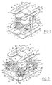
- the device shown in Figure 1 includes an element mass 1 of mass m3 which, in the case of an active mixer, includes a generator electrodynamics or variable reluctance.
- a plate 5 fixed to the element 1 carries to its ends two springs 3 which give the mass-spring system thus formed stiffness K3. These two springs 3 rest on cylindrical pads 31 carried by a plate 2 which is coupled to a structure whose vibrations are to be suppressed or to which we want to communicate vibrations.
- the plate 5 carries a plate 6 at ends of which are fixed the branches 81 of two springs 8 which have two opposite branches 81 and 83 separated by a slot 82 and connected together by the sectors 85.
- the element 1 has a plate 7 at the part bottom of which is mounted a plate 6 at the ends of which are fixed branches 91 of two springs 9 similar to springs 58 and which have two opposite branches 91 and 93 separated by a slot 92 and connected by sectors 95.
- the branches 83 and 93 of the springs 8 and 9 are integral with the uprights 84 perpendicular to the plane of the plate 2 and which are integral with the latter. Plates 6 being integral with the plate 5 and the plate 7, the springs 8 and 9 make it possible to center the 1-spring 3 mass assembly during its movements perpendicular to the plate 2.
- the uprights 84 can be used to dispose of the masses additional which can be coupled to main ground 1 or decoupled from this, in order to vary the dynamic mass of the drummer, and therefore to modify the resonance conditions.
- a module 10 of additional mass to add a mass m4 to the main mass m3 has two electromagnets 102 mounted at both ends of the link arm 110 and 111, notched at 112 in view of the passage of an upright 84.
- Springs 115 having arms 116 form a zigzag paths, which are separated by slots 117 extending from edges opposite 113 and 119. These springs 115 serve to suspend and guide the mass m4 which consists of the two electromagnets 102 and the connecting parts 110 and 111.
- Each spring 115 is mounted on two pairs of tie rods 101 and 103.
- the tie rods 101 are integral with a fixed plate 120 integral with its opening 125 the amount 84.
- the tie rods 103 mounted opposite the tie rods 101, are integral with the corresponding electromagnet 102.
- For each electromagnet there are two pairs upper and lower of tie rods 101, and two pairs, upper and lower of tie rods 103. This gives a degree of freedom parallel to the direction of displacement of the element 1, that is to say perpendicular to the plane of the plate 2.
- FIG. 5 shows the device 20 which makes it possible to couple the mass additional m4 (ref. 10) to main mass 3. It has two masses ferromagnetic 204 for example laminated mounted at the end of a blade flexion 201 fixed at its openings 202 on a lateral face of the plate 7. This bending blade has a high stiffness in the direction of movement of the mass 1 of the mixer, that is, of the vibration to be generated or to be attenuated, but a much lower stiffness in the plane perpendicular to said direction of movement.
- the ferromagnetic masses 204 are located opposite the electromagnets 102. In this way, the magnetic circuits of the electromagnets 102 close on the magnetic masses 204.
- the coupling is carried out as follows: the activation of the electromagnets 102 causes the application of masses 204 on the surface of the electromagnets 102, and therefore a mechanical coupling of the additional mass. Given that the plate 7 is integral in displacement with the main mass, the mass additional is also driven in a movement parallel to the axis of uprights 84, which is made possible by the suspension effect provided by the springs lamellar 115.
- Figures 2 to 5 allows for a variation of the mass of the mixer by coupling one or more additional masses specified values, which allows you to change the frequency of the mixer in order to process vibrations whose frequency can change.
- the four are simultaneously excited electromagnets to couple the two modules 10 of the main element 1.
- leaf springs 115 which are sufficiently stiff in the plane perpendicular to the direction of movement of the beater to avoid their movement in this plane and flexible enough in the direction of movement of the drummer to accompany him in his movements, the flexibility being fixed so as to achieve with the new mass and characteristics drummer's antecedents the new chord of it.
- the stiffness of these blades can be supplemented by those of springs acting in parallel with them to achieve the new chord, (which amounts, in a way, to connecting to the initial drummer a new beater placed in parallel).
- the device described allows generate significant dynamic forces at low frequency according to a setpoint supplied to an electronic unit.
- the effort is generated inertially, that is to say using the principle of action-reaction applying to a mass excited in effort.
- the mass is constituted by the mass of the generator body.
- the invention can be implemented using a generator variable reluctance incorporated into main mass 1 and its control via a digital computer whose algorithm linearizes it in a manner known per se force-displacement characteristic, both as a force and mass generator in a mass-spring system in order to introduce significant forces at low frequency in a structure.
- the mass m2 is made up of the mass mobile of an electromagnetic generator (with variable reluctance) or of a generator electrodynamics.
- the mass m2 and the elastic connection of rigidity K2 constitutes a oscillating mechanical system whose amplification can be exploited at resonance in the limit of admissible travel.
- This technique is commonly used with generators electrodynamics (coils plunging into a constant field).
- variable reluctance generators which provide significant efforts in a volume then reduced is hardly possible in low frequency, because their travel is limited by the need for air gaps weak to generate effort.
- the solution is obtained by exciting an oscillating system mass-spring at a frequency close to its natural frequency. We then benefit from amplification coefficient of such a system, without the need to generate an effort important initial.
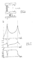
- the assembly diagram (see Figure 6) implements a generator having a mass m2 suspended with a stiffness K2, which excites the mass m3 of the auxiliary mass-spring system, having an auxiliary mass m3 and having a stiffness K3.
- the mass m2 consists of the main mass 1 which is coupled to a generator of which it constitutes the mobile mass.
- the stiffness K2 is defined by the springs 3.
- Z 2 / U [(m2 + m3) p 2 + K3)] / [m2.m3.p 4 + (K2.m2 + m2.K3 + K2.m3) p 2 + K2.K3]
- m2 - ⁇ f 1 1 ⁇ 2 ⁇ K 3 / ( m 2 + m 3)
- the device has two resonance frequencies f 0 and f 2 for which there is a large amplification of the force generated, and an anti-resonance frequency f1 corresponding to the proper mode of the masses m2 + m3 on the spring K3.
- this amplitude z 2 can become very large and lead to saturation, or even destruction of the actuator. On the other hand, we note that this amplitude becomes very low around the antiresonance f 1 . In the case of a variable reluctance generator, this amplitude z 2 is the variation of the air gap, which means that it is therefore possible to use a small air gap and consequently have a large generated force.
- the Ft / U ratio is always greater than 1, which that we still take advantage of mechanical amplification.
- the generator is preferably of the variable reluctance type with an auxiliary mobile mass of value m 2 , the main mass being adjusted to the value m3.
Landscapes
- Engineering & Computer Science (AREA)
- General Engineering & Computer Science (AREA)
- Structural Engineering (AREA)
- Mechanical Engineering (AREA)
- Life Sciences & Earth Sciences (AREA)
- Paleontology (AREA)
- Physics & Mathematics (AREA)
- Mining & Mineral Resources (AREA)
- Soil Sciences (AREA)
- Civil Engineering (AREA)
- Environmental & Geological Engineering (AREA)
- Agronomy & Crop Science (AREA)
- General Life Sciences & Earth Sciences (AREA)
- Electromagnetism (AREA)
- Apparatuses For Generation Of Mechanical Vibrations (AREA)
- Electrotherapy Devices (AREA)
- Compositions Of Oxide Ceramics (AREA)
- Inorganic Compounds Of Heavy Metals (AREA)
- Vibration Prevention Devices (AREA)
Applications Claiming Priority (3)
| Application Number | Priority Date | Filing Date | Title |
|---|---|---|---|
| FR9905111A FR2792554B1 (fr) | 1999-04-22 | 1999-04-22 | Dispositif resonant, tel que batteur ou generateur d'efforts |
| FR9905111 | 1999-04-22 | ||
| US09/559,774 US6374968B1 (en) | 1999-04-22 | 2000-04-27 | Resonant device, such as a striker or load generator |
Publications (2)
| Publication Number | Publication Date |
|---|---|
| EP1052028A1 true EP1052028A1 (de) | 2000-11-15 |
| EP1052028B1 EP1052028B1 (de) | 2006-06-14 |
Family
ID=26234928
Family Applications (1)
| Application Number | Title | Priority Date | Filing Date |
|---|---|---|---|
| EP00400995A Expired - Lifetime EP1052028B1 (de) | 1999-04-22 | 2000-04-11 | Resonanzvorrichtung wie Schläger oder Krafterzeuger |
Country Status (7)
| Country | Link |
|---|---|
| US (1) | US6374968B1 (de) |
| EP (1) | EP1052028B1 (de) |
| JP (1) | JP2000317399A (de) |
| AT (1) | ATE329698T1 (de) |
| DE (1) | DE60028654T2 (de) |
| ES (1) | ES2265889T3 (de) |
| FR (1) | FR2792554B1 (de) |
Cited By (2)
| Publication number | Priority date | Publication date | Assignee | Title |
|---|---|---|---|---|
| CN101406881B (zh) * | 2008-08-26 | 2010-11-10 | 张二洪 | 三质体垂直振动装置 |
| CN105912044A (zh) * | 2016-06-06 | 2016-08-31 | 上海交通大学 | 频率分辨率高细分可调谐动力吸振器 |
Families Citing this family (17)
| Publication number | Priority date | Publication date | Assignee | Title |
|---|---|---|---|---|
| JP4614531B2 (ja) * | 2000-12-18 | 2011-01-19 | 株式会社ミツトヨ | 加振機 |
| FR2875880A1 (fr) | 2004-09-30 | 2006-03-31 | Peugeot Citroen Automobiles Sa | Procede et dispositif d'amortissement des vibrations d'une structure |
| US7726452B2 (en) * | 2005-06-02 | 2010-06-01 | Technical Manufacturing Corporation | Systems and methods for active vibration damping |
| JP2007111619A (ja) * | 2005-10-19 | 2007-05-10 | Alps Electric Co Ltd | 振動発生装置 |
| JP2007130582A (ja) * | 2005-11-10 | 2007-05-31 | Alps Electric Co Ltd | 振動発生装置及びこれを用いた入出力機器 |
| ES2308891B1 (es) * | 2006-06-01 | 2009-10-23 | Universitat Politecnica De Catalunya | Planta para la caracterizacion dinamica axial y transversal de muelles y aisladores de vibraciones. |
| JP4319213B2 (ja) * | 2006-10-16 | 2009-08-26 | アルプス電気株式会社 | 振動発生装置 |
| CN101587008B (zh) * | 2009-07-20 | 2011-03-16 | 中国航空工业第一集团公司北京长城计量测试技术研究所 | 电动振动台振动增强装置 |
| EP2558649B1 (de) | 2010-04-16 | 2014-11-19 | Ammann Schweiz AG | Anordnung zur bereitstellung einer pulsierenden druckkraft |
| CN101893051A (zh) * | 2010-07-23 | 2010-11-24 | 苏州盟通利机电设备有限公司 | 压缩式机械设备减震方法 |
| CN102642453A (zh) * | 2012-04-18 | 2012-08-22 | 杨亦勇 | 一种将频率共震应用于电动汽车动能发电的方法 |
| CN103542031B (zh) * | 2013-07-26 | 2015-08-19 | 中国船舶重工集团公司第七一九研究所 | 一种三向可调频动力吸振器 |
| US9765847B1 (en) * | 2014-04-07 | 2017-09-19 | California Dynamics Corporation | Vibration isolation and seismic restraint apparatus and methods |
| CA3008230A1 (en) * | 2015-12-14 | 2017-06-22 | Indian Industries, Inc. | Basketball goal with vibration damping |
| CN108130899A (zh) * | 2017-11-20 | 2018-06-08 | 深圳市晟祥知识产权有限公司 | 一种市政工程施工用撞击式土壤压实设备 |
| FR3097285B1 (fr) * | 2019-06-14 | 2021-05-28 | Hutchinson | Système d’amortissement des vibrations générées par un dispositif et procédé associé. |
| CN112982362A (zh) * | 2021-02-23 | 2021-06-18 | 吴佳琪 | 一种依据地面紧实度调节锤重的地基夯实装置 |
Citations (4)
| Publication number | Priority date | Publication date | Assignee | Title |
|---|---|---|---|---|
| DE2302098A1 (de) * | 1973-01-17 | 1974-07-18 | Licentia Gmbh | Magnetvibrator |
| US3909148A (en) * | 1972-06-24 | 1975-09-30 | Koehring Gmbh Bomag Division | Vibratory compacting machine |
| JPS57186651A (en) * | 1981-05-13 | 1982-11-17 | Nissan Motor Co Ltd | Shock-proof mount of vibration body |
| JPH01120453A (ja) * | 1987-11-04 | 1989-05-12 | Mitsubishi Electric Corp | 動吸振器 |
Family Cites Families (17)
| Publication number | Priority date | Publication date | Assignee | Title |
|---|---|---|---|---|
| US4365770A (en) * | 1978-08-04 | 1982-12-28 | United Technologies Corp. | Fixed position variable frequency pendular-type vibration absorber |
| US4213518A (en) * | 1978-08-04 | 1980-07-22 | United Technologies Corporation | Fixed position pendular-type vibration absorber with linearization at fixed or variable frequencies |
| JPS5671934A (en) | 1979-11-16 | 1981-06-15 | Nec Home Electronics Ltd | Semiconductor manufacturing device |
| DE3529199A1 (de) * | 1984-08-16 | 1986-02-27 | Nissan Motor Co., Ltd., Yokohama, Kanagawa | Schwingungsdaempfungssystem |
| JPS62278540A (ja) | 1986-05-27 | 1987-12-03 | Canon Inc | 液晶素子、その配向制御法及びその駆動法 |
| DE4492362T1 (de) * | 1993-04-09 | 1995-07-20 | Nippon Steel Corp | Vibrationsisolierstütze |
| US6032770A (en) * | 1993-04-12 | 2000-03-07 | Raytheon Company | Low force actuator for suspension control |
| US5456341A (en) * | 1993-04-23 | 1995-10-10 | Moog Inc. | Method and apparatus for actively adjusting and controlling a resonant mass-spring system |
| US5660255A (en) * | 1994-04-04 | 1997-08-26 | Applied Power, Inc. | Stiff actuator active vibration isolation system |
| US5431261A (en) * | 1994-05-12 | 1995-07-11 | University Of Connecticut | Delayed resonators as active dynamic absorbers |
| US5505282A (en) * | 1994-09-06 | 1996-04-09 | The University Of Connecticut | Single mass dual frequency fixed delayed resonator |
| JPH08309283A (ja) * | 1995-03-15 | 1996-11-26 | Matsushita Electric Works Ltd | 往復運動型加振装置 |
| JP3538479B2 (ja) * | 1995-06-26 | 2004-06-14 | 東海ゴム工業株式会社 | ダブルマス式ダイナミックダンパおよびダイナミックダンパ付駆動車軸 |
| CN1077966C (zh) * | 1996-04-08 | 2002-01-16 | 株式会社三角工具加工 | 具有阻尼特性的磁弹簧和具有所述磁弹簧的振动机构 |
| US6009985A (en) * | 1997-02-10 | 2000-01-04 | Lord Corporation | Efficient multi-directional active vibration absorber assembly |
| JPH11230246A (ja) * | 1998-02-18 | 1999-08-27 | Tokkyo Kiki Kk | アクティブ除振装置 |
| US6202960B1 (en) * | 1998-11-06 | 2001-03-20 | The Boeing Company | Aircraft landing gear absorber |
-
1999
- 1999-04-22 FR FR9905111A patent/FR2792554B1/fr not_active Expired - Fee Related
-
2000
- 2000-04-11 EP EP00400995A patent/EP1052028B1/de not_active Expired - Lifetime
- 2000-04-11 AT AT00400995T patent/ATE329698T1/de not_active IP Right Cessation
- 2000-04-11 DE DE60028654T patent/DE60028654T2/de not_active Expired - Lifetime
- 2000-04-11 ES ES00400995T patent/ES2265889T3/es not_active Expired - Lifetime
- 2000-04-24 JP JP2000122665A patent/JP2000317399A/ja not_active Ceased
- 2000-04-27 US US09/559,774 patent/US6374968B1/en not_active Expired - Lifetime
Patent Citations (4)
| Publication number | Priority date | Publication date | Assignee | Title |
|---|---|---|---|---|
| US3909148A (en) * | 1972-06-24 | 1975-09-30 | Koehring Gmbh Bomag Division | Vibratory compacting machine |
| DE2302098A1 (de) * | 1973-01-17 | 1974-07-18 | Licentia Gmbh | Magnetvibrator |
| JPS57186651A (en) * | 1981-05-13 | 1982-11-17 | Nissan Motor Co Ltd | Shock-proof mount of vibration body |
| JPH01120453A (ja) * | 1987-11-04 | 1989-05-12 | Mitsubishi Electric Corp | 動吸振器 |
Non-Patent Citations (2)
| Title |
|---|
| PATENT ABSTRACTS OF JAPAN vol. 007, no. 031 (M - 192) 8 February 1983 (1983-02-08) * |
| PATENT ABSTRACTS OF JAPAN vol. 013, no. 365 (M - 859) 15 August 1989 (1989-08-15) * |
Cited By (3)
| Publication number | Priority date | Publication date | Assignee | Title |
|---|---|---|---|---|
| CN101406881B (zh) * | 2008-08-26 | 2010-11-10 | 张二洪 | 三质体垂直振动装置 |
| CN105912044A (zh) * | 2016-06-06 | 2016-08-31 | 上海交通大学 | 频率分辨率高细分可调谐动力吸振器 |
| CN105912044B (zh) * | 2016-06-06 | 2018-08-03 | 上海交通大学 | 频率分辨率可调谐动力吸振器 |
Also Published As
| Publication number | Publication date |
|---|---|
| FR2792554B1 (fr) | 2001-06-29 |
| DE60028654D1 (de) | 2006-07-27 |
| JP2000317399A (ja) | 2000-11-21 |
| DE60028654T2 (de) | 2007-06-06 |
| US6374968B1 (en) | 2002-04-23 |
| FR2792554A1 (fr) | 2000-10-27 |
| EP1052028B1 (de) | 2006-06-14 |
| ES2265889T3 (es) | 2007-03-01 |
| ATE329698T1 (de) | 2006-07-15 |
Similar Documents
| Publication | Publication Date | Title |
|---|---|---|
| EP1052028B1 (de) | Resonanzvorrichtung wie Schläger oder Krafterzeuger | |
| Halim et al. | Frequency up-converted wide bandwidth piezoelectric energy harvester using mechanical impact | |
| EP2908188B1 (de) | Regulierung eines resonators einer uhr durch einwirkung auf die steifheit eines elastischen rückstellmittels | |
| CN104904110B (zh) | 能量采集设备和方法 | |
| FR2517823A1 (fr) | Gyroscope oscillant | |
| GB2425222A (en) | An electromechanical generator for converting mechanical vibraional energy into electrical energy | |
| EP2463731B1 (de) | Schlagwerkmechanismus einer Armbanduhr | |
| EP2908187B1 (de) | Regulierung eines Resonators einer Uhr durch Einwirkung auf die aktive Länge einer Spiralfeder | |
| CH632851A5 (fr) | Dispositif vibrant pour le traitement d'un faisceau optique. | |
| FR2594547A1 (fr) | Transducteur de force a barreau vibrant comportant un seul ressort isolant | |
| EP1052029B1 (de) | Resonanzvorrichtung wie Schläger oder Krafterzeuger | |
| US20110260802A1 (en) | Parametric feedback oscillators | |
| EP2908184A1 (de) | Wartungs- und Regulierungsverfahren eines Uhrenresonators | |
| EP2513992A1 (de) | Stromgenerator mit energierückgewinnung aus mechanischer vibration | |
| WO2007020383A1 (en) | An electromechanical generator for converting mechanical vibrational energy into electrical energy | |
| FR2479034A1 (fr) | Systeme vibrant electromagnetique pouvant fonctionner a de grandes amplitudes | |
| EP1276126A1 (de) | Mikroelektromechanisches Bauelement | |
| EP4075647B1 (de) | Elektromagnetische vorrichtung zur umwandlung von mechanischer energie in elektrische energie | |
| EP1151246B1 (de) | Monolithische struktur eines schwingungs-gyroskops | |
| FR3061705A1 (fr) | Composant micromecanique et son procede de fabrication | |
| BRPI0402498B1 (pt) | batedor dinâmico e processo de utilização do mesmo | |
| FR2712514A1 (fr) | Moteur à ultrasons. | |
| Rastegar et al. | Novel two-stage piezoelectric-based electrical energy generators for low and variable speed rotary machinery | |
| Roy et al. | Tuning non-linearity in cascaded tapered spring topologies of electromagnetic-vibrational energy harvesters with enhanced figure of merit | |
| EP2908186B1 (de) | Frequenzregelung eines resonators einer uhr durch bewegung der spiralfeder |
Legal Events
| Date | Code | Title | Description |
|---|---|---|---|
| PUAI | Public reference made under article 153(3) epc to a published international application that has entered the european phase |
Free format text: ORIGINAL CODE: 0009012 |
|
| AK | Designated contracting states |
Kind code of ref document: A1 Designated state(s): AT BE CH CY DE DK ES FI FR GB GR IE IT LI LU MC NL PT SE |
|
| AX | Request for extension of the european patent |
Free format text: AL;LT;LV;MK;RO;SI |
|
| 17P | Request for examination filed |
Effective date: 20010327 |
|
| AKX | Designation fees paid |
Free format text: AT BE CH CY DE DK ES FI FR GB GR IE IT LI LU MC NL PT SE |
|
| 17Q | First examination report despatched |
Effective date: 20050607 |
|
| GRAP | Despatch of communication of intention to grant a patent |
Free format text: ORIGINAL CODE: EPIDOSNIGR1 |
|
| GRAS | Grant fee paid |
Free format text: ORIGINAL CODE: EPIDOSNIGR3 |
|
| GRAA | (expected) grant |
Free format text: ORIGINAL CODE: 0009210 |
|
| AK | Designated contracting states |
Kind code of ref document: B1 Designated state(s): AT BE CH CY DE DK ES FI FR GB GR IE IT LI LU MC NL PT SE |
|
| PG25 | Lapsed in a contracting state [announced via postgrant information from national office to epo] |
Ref country code: IT Free format text: LAPSE BECAUSE OF FAILURE TO SUBMIT A TRANSLATION OF THE DESCRIPTION OR TO PAY THE FEE WITHIN THE PRESCRIBED TIME-LIMIT;WARNING: LAPSES OF ITALIAN PATENTS WITH EFFECTIVE DATE BEFORE 2007 MAY HAVE OCCURRED AT ANY TIME BEFORE 2007. THE CORRECT EFFECTIVE DATE MAY BE DIFFERENT FROM THE ONE RECORDED. Effective date: 20060614 Ref country code: IE Free format text: LAPSE BECAUSE OF FAILURE TO SUBMIT A TRANSLATION OF THE DESCRIPTION OR TO PAY THE FEE WITHIN THE PRESCRIBED TIME-LIMIT Effective date: 20060614 Ref country code: AT Free format text: LAPSE BECAUSE OF FAILURE TO SUBMIT A TRANSLATION OF THE DESCRIPTION OR TO PAY THE FEE WITHIN THE PRESCRIBED TIME-LIMIT Effective date: 20060614 Ref country code: FI Free format text: LAPSE BECAUSE OF FAILURE TO SUBMIT A TRANSLATION OF THE DESCRIPTION OR TO PAY THE FEE WITHIN THE PRESCRIBED TIME-LIMIT Effective date: 20060614 |
|
| REG | Reference to a national code |
Ref country code: GB Ref legal event code: FG4D Free format text: NOT ENGLISH |
|
| REG | Reference to a national code |
Ref country code: CH Ref legal event code: EP |
|
| REG | Reference to a national code |
Ref country code: IE Ref legal event code: FG4D Free format text: LANGUAGE OF EP DOCUMENT: FRENCH |
|
| REF | Corresponds to: |
Ref document number: 60028654 Country of ref document: DE Date of ref document: 20060727 Kind code of ref document: P |
|
| RAP2 | Party data changed (patent owner data changed or rights of a patent transferred) |
Owner name: HUTCHINSON |
|
| PG25 | Lapsed in a contracting state [announced via postgrant information from national office to epo] |
Ref country code: DK Free format text: LAPSE BECAUSE OF FAILURE TO SUBMIT A TRANSLATION OF THE DESCRIPTION OR TO PAY THE FEE WITHIN THE PRESCRIBED TIME-LIMIT Effective date: 20060914 |
|
| REG | Reference to a national code |
Ref country code: SE Ref legal event code: TRGR |
|
| REG | Reference to a national code |
Ref country code: CH Ref legal event code: NV Representative=s name: ISLER & PEDRAZZINI AG |
|
| NLT2 | Nl: modifications (of names), taken from the european patent patent bulletin |
Owner name: HUTCHINSON Effective date: 20060830 |
|
| PG25 | Lapsed in a contracting state [announced via postgrant information from national office to epo] |
Ref country code: PT Free format text: LAPSE BECAUSE OF FAILURE TO SUBMIT A TRANSLATION OF THE DESCRIPTION OR TO PAY THE FEE WITHIN THE PRESCRIBED TIME-LIMIT Effective date: 20061114 |
|
| GBT | Gb: translation of ep patent filed (gb section 77(6)(a)/1977) |
Effective date: 20061123 |
|
| NLS | Nl: assignments of ep-patents |
Owner name: HUTCHINSON S.A. Effective date: 20061110 |
|
| REG | Reference to a national code |
Ref country code: ES Ref legal event code: FG2A Ref document number: 2265889 Country of ref document: ES Kind code of ref document: T3 |
|
| PLBE | No opposition filed within time limit |
Free format text: ORIGINAL CODE: 0009261 |
|
| STAA | Information on the status of an ep patent application or granted ep patent |
Free format text: STATUS: NO OPPOSITION FILED WITHIN TIME LIMIT |
|
| 26N | No opposition filed |
Effective date: 20070315 |
|
| REG | Reference to a national code |
Ref country code: GB Ref legal event code: 732E |
|
| REG | Reference to a national code |
Ref country code: CH Ref legal event code: PCAR Free format text: ISLER & PEDRAZZINI AG;POSTFACH 1772;8027 ZUERICH (CH) |
|
| BERE | Be: lapsed |
Owner name: VIBRACHOC Effective date: 20070430 |
|
| PG25 | Lapsed in a contracting state [announced via postgrant information from national office to epo] |
Ref country code: BE Free format text: LAPSE BECAUSE OF NON-PAYMENT OF DUE FEES Effective date: 20070430 |
|
| PG25 | Lapsed in a contracting state [announced via postgrant information from national office to epo] |
Ref country code: GR Free format text: LAPSE BECAUSE OF FAILURE TO SUBMIT A TRANSLATION OF THE DESCRIPTION OR TO PAY THE FEE WITHIN THE PRESCRIBED TIME-LIMIT Effective date: 20060915 |
|
| PG25 | Lapsed in a contracting state [announced via postgrant information from national office to epo] |
Ref country code: MC Free format text: LAPSE BECAUSE OF NON-PAYMENT OF DUE FEES Effective date: 20070430 |
|
| PG25 | Lapsed in a contracting state [announced via postgrant information from national office to epo] |
Ref country code: LU Free format text: LAPSE BECAUSE OF NON-PAYMENT OF DUE FEES Effective date: 20070411 Ref country code: CY Free format text: LAPSE BECAUSE OF FAILURE TO SUBMIT A TRANSLATION OF THE DESCRIPTION OR TO PAY THE FEE WITHIN THE PRESCRIBED TIME-LIMIT Effective date: 20060614 |
|
| PGFP | Annual fee paid to national office [announced via postgrant information from national office to epo] |
Ref country code: GB Payment date: 20140422 Year of fee payment: 15 |
|
| PGFP | Annual fee paid to national office [announced via postgrant information from national office to epo] |
Ref country code: ES Payment date: 20140428 Year of fee payment: 15 Ref country code: IT Payment date: 20140430 Year of fee payment: 15 Ref country code: SE Payment date: 20140418 Year of fee payment: 15 Ref country code: CH Payment date: 20140418 Year of fee payment: 15 Ref country code: DE Payment date: 20140418 Year of fee payment: 15 Ref country code: FR Payment date: 20140429 Year of fee payment: 15 Ref country code: NL Payment date: 20140418 Year of fee payment: 15 |
|
| REG | Reference to a national code |
Ref country code: DE Ref legal event code: R119 Ref document number: 60028654 Country of ref document: DE |
|
| REG | Reference to a national code |
Ref country code: CH Ref legal event code: PL |
|
| REG | Reference to a national code |
Ref country code: SE Ref legal event code: EUG |
|
| GBPC | Gb: european patent ceased through non-payment of renewal fee |
Effective date: 20150411 |
|
| REG | Reference to a national code |
Ref country code: NL Ref legal event code: MM Effective date: 20150501 |
|
| PG25 | Lapsed in a contracting state [announced via postgrant information from national office to epo] |
Ref country code: IT Free format text: LAPSE BECAUSE OF NON-PAYMENT OF DUE FEES Effective date: 20150411 Ref country code: CH Free format text: LAPSE BECAUSE OF NON-PAYMENT OF DUE FEES Effective date: 20150430 Ref country code: DE Free format text: LAPSE BECAUSE OF NON-PAYMENT OF DUE FEES Effective date: 20151103 Ref country code: LI Free format text: LAPSE BECAUSE OF NON-PAYMENT OF DUE FEES Effective date: 20150430 Ref country code: GB Free format text: LAPSE BECAUSE OF NON-PAYMENT OF DUE FEES Effective date: 20150411 |
|
| REG | Reference to a national code |
Ref country code: FR Ref legal event code: ST Effective date: 20151231 |
|
| PG25 | Lapsed in a contracting state [announced via postgrant information from national office to epo] |
Ref country code: SE Free format text: LAPSE BECAUSE OF NON-PAYMENT OF DUE FEES Effective date: 20150412 Ref country code: FR Free format text: LAPSE BECAUSE OF NON-PAYMENT OF DUE FEES Effective date: 20150430 |
|
| PG25 | Lapsed in a contracting state [announced via postgrant information from national office to epo] |
Ref country code: NL Free format text: LAPSE BECAUSE OF NON-PAYMENT OF DUE FEES Effective date: 20150501 |
|
| REG | Reference to a national code |
Ref country code: ES Ref legal event code: FD2A Effective date: 20160526 |
|
| PG25 | Lapsed in a contracting state [announced via postgrant information from national office to epo] |
Ref country code: ES Free format text: LAPSE BECAUSE OF NON-PAYMENT OF DUE FEES Effective date: 20150412 |