EP1052414A1 - Fluidventilvorrichtung, insbesondere für hydraulische Fernsteuerung - Google Patents
Fluidventilvorrichtung, insbesondere für hydraulische Fernsteuerung Download PDFInfo
- Publication number
- EP1052414A1 EP1052414A1 EP00401265A EP00401265A EP1052414A1 EP 1052414 A1 EP1052414 A1 EP 1052414A1 EP 00401265 A EP00401265 A EP 00401265A EP 00401265 A EP00401265 A EP 00401265A EP 1052414 A1 EP1052414 A1 EP 1052414A1
- Authority
- EP
- European Patent Office
- Prior art keywords
- plunger
- fluid
- smaller radius
- bore
- active part
- Prior art date
- Legal status (The legal status is an assumption and is not a legal conclusion. Google has not performed a legal analysis and makes no representation as to the accuracy of the status listed.)
- Granted
Links
- 239000012530 fluid Substances 0.000 title claims abstract description 51
- 230000004323 axial length Effects 0.000 claims abstract description 4
- 230000009467 reduction Effects 0.000 claims description 9
- 239000003638 chemical reducing agent Substances 0.000 claims description 7
- 238000006073 displacement reaction Methods 0.000 claims 1
- 230000000284 resting effect Effects 0.000 abstract 1
- 241001415961 Gaviidae Species 0.000 description 11
- 238000003754 machining Methods 0.000 description 4
- 230000007935 neutral effect Effects 0.000 description 3
- 238000004519 manufacturing process Methods 0.000 description 2
- 210000000056 organ Anatomy 0.000 description 2
- 230000004044 response Effects 0.000 description 2
- 230000009471 action Effects 0.000 description 1
- 210000004027 cell Anatomy 0.000 description 1
- 230000001112 coagulating effect Effects 0.000 description 1
- 239000000470 constituent Substances 0.000 description 1
- 230000000994 depressogenic effect Effects 0.000 description 1
- 238000009432 framing Methods 0.000 description 1
- 238000009434 installation Methods 0.000 description 1
Images


Classifications
-
- F—MECHANICAL ENGINEERING; LIGHTING; HEATING; WEAPONS; BLASTING
- F15—FLUID-PRESSURE ACTUATORS; HYDRAULICS OR PNEUMATICS IN GENERAL
- F15B—SYSTEMS ACTING BY MEANS OF FLUIDS IN GENERAL; FLUID-PRESSURE ACTUATORS, e.g. SERVOMOTORS; DETAILS OF FLUID-PRESSURE SYSTEMS, NOT OTHERWISE PROVIDED FOR
- F15B13/00—Details of servomotor systems ; Valves for servomotor systems
- F15B13/02—Fluid distribution or supply devices characterised by their adaptation to the control of servomotors
- F15B13/04—Fluid distribution or supply devices characterised by their adaptation to the control of servomotors for use with a single servomotor
- F15B13/042—Fluid distribution or supply devices characterised by their adaptation to the control of servomotors for use with a single servomotor operated by fluid pressure
- F15B13/0422—Fluid distribution or supply devices characterised by their adaptation to the control of servomotors for use with a single servomotor operated by fluid pressure with manually-operated pilot valves, e.g. joysticks
Definitions
- the present invention relates to improvements brought to the fluid dispensing devices, especially for hydraulic remote control, such as those called “hydraulic manipulators”, including minus a pressure reducer mounted in a body and a control unit capable of modifying the calibration of the reducer, which reducer comprises a plunger movable, by the aforesaid control member, in a body cavity which includes, on one side, a connected housing to a hydraulic fluid return pipe T and containing a reduction spring for the reduction gear and a spring plunger, and on the other side, a bore communicating, axially opposite the above-mentioned housing, with a remote control fluid flow chamber and, laterally, with a chamber supplied with fluid under pressure P from a source of fluid under pressure, said bore housing an active part of the plunger traversed by a channel having an axial orifice leading to the departure chamber and a lateral orifice suitable for being selectively connected to the housing or the supply chamber to ensure the fluid pressure reduction function of remote control when moving the diver in the bore.
- Such a device is described for example in the documents FR 2 376 978 or FR 2 507 732.
- a known device partially shown in section in fig. 1 of the accompanying drawings, comprises a body (can be made up of several parts to facilitate the installation of components internal) in which at least one reduction gear is fitted fluid pressure 2.
- This reducer includes a plunger 3 able to move in a cavity 4 formed in the body 1.
- This cavity 4 has, on one side, an enlarged housing 5 connected to a return channel to the tank (T) and in which is disposed a calibration spring 6 taking support between a shoulder 7 of the plunger and a cup 8 movable in the housing 5 near the end free of the plunger and, on the other side, a bore 9 in which an active part 10 of the plunger can be moved to perform the pressure reduction function (P) fluid that is brought in from a source through an orifice inlet (not visible) connected to bore 9 by a chamber 12 opening radially therein, while that bore 9 opens out lower into a chamber 13 for the remote control fluid (D).
- the part active or plunger 10 of the plunger has a channel axial interior 22 opening at the base of the piston 10 into the starting room 13 and ending superiorly with a radial bore 23 opening laterally.
- the plunger 3 further includes a rod portion 14, overcoming the active part 10 and extending substantially in the cavity 5 while being surrounded coaxially by the calibration spring 6; this part of rod 14 passes through the cup 8 and ends with a head enlarged 15 defining a shoulder 16 for retaining the cup.
- a return spring 17, coaxial with the rod 14, is interposed between the cup 8 and a shoulder defined in the body 1, to push the cup upwards, that is to say towards its position defining a calibration minimum.
- the cup 8 is surmounted by a pusher 18 movable at free sliding in a body bore and making partially protruding from the body to be in contact a cam 19 able to pivot around an axis under the action an actuating member such as a handle 21.
- Such a remote control device gives entirely satisfaction in terms of its technical functioning, and it is widely used.
- a fluid dispensing device especially for hydraulic remote control is characterized, being arranged in accordance with the invention, in that the active part of the plunger has at least a portion of its periphery having a smaller radius over at least one angular sector and having sufficient axial length so that when the diver is moved from its rest position, a passage is established, between the above rooms receiving the supply fluid (P) and the starting fluid (D), through the interval defined by said portion of radius less and the bore as soon as the radial orifice of the channel inside the plunger is closed by the wall of the bore.
- the portion of smaller radius of the active part of the plunger is annular and coaxial with the active part of the plunger.
- the portion of smaller radius of the active part of the plunger is unique.
- multiple spoke portions less are provided on the active part of the plunger; in particular these portions of smaller radius are arranged symmetrically, especially two in number diametrically opposite or preferably the number of four, two to two diametrically opposite.
- each portion of smaller radius is a dish.
- this arrangement selectively provides two separate circuits for fluid flow, of a hand, on the periphery of the diver with a section of increased passage for the flow of fluid from the chamber supply to the departure chamber (regulation) and, on the other hand, axially through the central channel of the plunger for the reverse flow of the fluid from the departure chamber to the reservoir.
- the increase in the cross section as well supplied to the fluid during the operating phase in regulation results in a significant gain in the time of response of the device, which may be accompanied by a significant reduction or even cancellation of noise fluid flow.
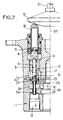
- FIG. 2 there is depicted a portion of fluid dispensing device having a similar overall concept (although not identical in its details) to that of the prior device illustrated in FIG. 1.
- the part active 10 of the diver 3 has at least a portion 24 of its periphery with a smaller radius over at least one angular sector and having sufficient axial length so that when the diver is moved from its rest position, a passage is established between the above chambers 12 receiving the fluid supply P and 13 receiving the starting fluid D, through the interval defined by said portion 24 of smaller radius and the bore 9 as soon as the radial orifice 23 of the channel 22 inside the plunger is closed by the wall of bore 9.
- the smallest radius portion of the part active of the diver is axially framed by two zones having the nominal diameter of the active part, namely the terminal zone 10a of the plunger and zone 10b containing the radial hole (s) 23 of the inner channel 22.
- the device In FIG. 2, the device is in the neutral position or rest, the cam 19 being arranged coaxially in the axis 25 of the device.
- the pusher 18 is returned to the projecting position (high position) by the return spring 17 and, the pusher 18 coagulating with the head 15 of the plunger 3, keeps this plunger in neutral position shown in Figure 2 in which the orifice lateral 23 of the inner channel 22 opens, completely or partially, in housing 5.
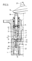
- the terminal portion 10a of the plunger is released from bore 9: the portion 24 of smaller radius of the active part 10 of the plunger and the bore 9 define between them a passage 26 which establishes a connection between the chamber 12 and the chamber 13.
- the pressurized fluid P can thus begin to flow towards the start D (room 13).
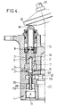
- the radial hole 23 When the plunger continues to be moved, the radial hole 23 first partially opens, then fully at the end of the stroke of the plunger, in chamber 12 (fig. 4). The fluid under pressure P then flows towards the start D, on the one hand, by passage 26 which remains open and, on the other hand, through channel 22.
- One solution may consist in producing said portion 24 in annular form so that the active part of the plunger is, in this zone, in the form of a revolution with a smaller radius than the two framing zones 10 a and 10 b (fig. 5) .
- This solution which is advantageous with regard to the sufficiency of the section of the annular passage 26 thus defined, nevertheless leads to insufficient guidance of the plunger 3 in the bore 9 (only the part of the bore comprised between the chamber 12 and the housing 5 ensures guiding the plunger when the end portion 10a is out of the bore).
- the radius reduction can be carried out in the form of a surface with different radius of curvature and / or center of curvature as shown in Figure 6, which leads to a passage 26 in lunula shape.
- the arrangement according to the invention leads to the result advantageous to establish two separate circulation circuits of the fluid, namely a circuit ensuring the connection between the chambers 12 (pressure supply P) and 13 (flow D) through the passage 26 and channel 22, and a circuit ensuring the connection between chamber 13 (outlet D) and housing 5 (return to tank T). It follows that, thanks to the implementation of the provisions of the invention, the passage section offered to the fluid is significantly increased compared to previous devices in which only the internal channel provided the fluid connection.
- the machining of the body 1 can be simplified notably, and therefore its cost price to be lowered, because, to form the chamber 12 for admitting the supply fluid under pressure P, it is no longer necessary to machine the interior of the corresponding groove, but a simple counterboring can be carried out flat concentrically with the departure chamber 13.
Landscapes
- Engineering & Computer Science (AREA)
- Physics & Mathematics (AREA)
- Fluid Mechanics (AREA)
- Mechanical Engineering (AREA)
- General Engineering & Computer Science (AREA)
- Multiple-Way Valves (AREA)
- Nozzles (AREA)
- Actuator (AREA)
- Details Of Reciprocating Pumps (AREA)
- Fluid-Pressure Circuits (AREA)
- Control Of Fluid Pressure (AREA)
- Fluid-Driven Valves (AREA)
Applications Claiming Priority (2)
| Application Number | Priority Date | Filing Date | Title |
|---|---|---|---|
| FR9906088 | 1999-05-12 | ||
| FR9906088A FR2793532B1 (fr) | 1999-05-12 | 1999-05-12 | Dispositif distributeur de fluide notamment pour telecommande hydraulique |
Publications (2)
| Publication Number | Publication Date |
|---|---|
| EP1052414A1 true EP1052414A1 (de) | 2000-11-15 |
| EP1052414B1 EP1052414B1 (de) | 2004-04-07 |
Family
ID=9545540
Family Applications (1)
| Application Number | Title | Priority Date | Filing Date |
|---|---|---|---|
| EP00401265A Expired - Lifetime EP1052414B1 (de) | 1999-05-12 | 2000-05-09 | Fluidventilvorrichtung, insbesondere für hydraulische Fernsteuerung |
Country Status (5)
| Country | Link |
|---|---|
| EP (1) | EP1052414B1 (de) |
| JP (1) | JP2000357016A (de) |
| AT (1) | ATE263929T1 (de) |
| DE (1) | DE60009598T2 (de) |
| FR (1) | FR2793532B1 (de) |
Cited By (2)
| Publication number | Priority date | Publication date | Assignee | Title |
|---|---|---|---|---|
| EP2066941A4 (de) * | 2006-09-26 | 2014-11-05 | Borgwarner Inc | Steuerdruckmagnetschalter mit direktantrieb |
| IT201600127801A1 (it) * | 2016-12-16 | 2018-06-16 | Walvoil Spa | Servocomando idraulico ad area differenziale |
Families Citing this family (2)
| Publication number | Priority date | Publication date | Assignee | Title |
|---|---|---|---|---|
| CN102007331B (zh) | 2008-04-28 | 2014-11-05 | 博格华纳公司 | 用于螺线管的液压路径安排的包覆模制或压入式套管 |
| FR2938309B1 (fr) * | 2008-11-12 | 2010-10-29 | Bosch Rexroth Dsi Sas | Dispositif de regulation de pression, notamment du type telecommande hydraulique |
Citations (8)
| Publication number | Priority date | Publication date | Assignee | Title |
|---|---|---|---|---|
| FR2273178A1 (de) * | 1974-05-31 | 1975-12-26 | Bennes Marrel | |
| GB1494400A (en) * | 1974-11-07 | 1977-12-07 | Nordhydraulic Ab | Device for hydraulic control of a centered multiposition directional control valve |
| FR2376978A1 (fr) | 1977-01-06 | 1978-08-04 | Rexroth Sigma | Perfectionnements aux dispositifs distributeurs de fluide, notamment pour telecommande hydraulique |
| WO1981003686A1 (en) * | 1980-06-16 | 1981-12-24 | Caterpillar Tractor Co | Pressure reducing valve with floating stem for make-up vent |
| FR2507732A1 (fr) | 1981-06-12 | 1982-12-17 | Rexroth Sigma | Perfectionnements apportes aux plongeurs pour reducteurs de pression de fluide, reducteurs et distributeurs equipes de tels plongeurs |
| US4461320A (en) * | 1981-07-09 | 1984-07-24 | Fiat Allis Europe S.P.A. | Manually operable hydraulic control device with hydraulic position retention |
| FR2557218A1 (fr) * | 1983-12-21 | 1985-06-28 | Bennes Marrel | Emetteur hydraulique de commande a distance avec amplificateurs de debit |
| GB2293642A (en) * | 1994-09-29 | 1996-04-03 | Dana Corp | Pre-detent tactile feedback assembly for a fluid control valve |
-
1999
- 1999-05-12 FR FR9906088A patent/FR2793532B1/fr not_active Expired - Fee Related
-
2000
- 2000-05-09 DE DE60009598T patent/DE60009598T2/de not_active Expired - Fee Related
- 2000-05-09 EP EP00401265A patent/EP1052414B1/de not_active Expired - Lifetime
- 2000-05-09 AT AT00401265T patent/ATE263929T1/de not_active IP Right Cessation
- 2000-05-12 JP JP2000139940A patent/JP2000357016A/ja active Pending
Patent Citations (8)
| Publication number | Priority date | Publication date | Assignee | Title |
|---|---|---|---|---|
| FR2273178A1 (de) * | 1974-05-31 | 1975-12-26 | Bennes Marrel | |
| GB1494400A (en) * | 1974-11-07 | 1977-12-07 | Nordhydraulic Ab | Device for hydraulic control of a centered multiposition directional control valve |
| FR2376978A1 (fr) | 1977-01-06 | 1978-08-04 | Rexroth Sigma | Perfectionnements aux dispositifs distributeurs de fluide, notamment pour telecommande hydraulique |
| WO1981003686A1 (en) * | 1980-06-16 | 1981-12-24 | Caterpillar Tractor Co | Pressure reducing valve with floating stem for make-up vent |
| FR2507732A1 (fr) | 1981-06-12 | 1982-12-17 | Rexroth Sigma | Perfectionnements apportes aux plongeurs pour reducteurs de pression de fluide, reducteurs et distributeurs equipes de tels plongeurs |
| US4461320A (en) * | 1981-07-09 | 1984-07-24 | Fiat Allis Europe S.P.A. | Manually operable hydraulic control device with hydraulic position retention |
| FR2557218A1 (fr) * | 1983-12-21 | 1985-06-28 | Bennes Marrel | Emetteur hydraulique de commande a distance avec amplificateurs de debit |
| GB2293642A (en) * | 1994-09-29 | 1996-04-03 | Dana Corp | Pre-detent tactile feedback assembly for a fluid control valve |
Cited By (3)
| Publication number | Priority date | Publication date | Assignee | Title |
|---|---|---|---|---|
| EP2066941A4 (de) * | 2006-09-26 | 2014-11-05 | Borgwarner Inc | Steuerdruckmagnetschalter mit direktantrieb |
| IT201600127801A1 (it) * | 2016-12-16 | 2018-06-16 | Walvoil Spa | Servocomando idraulico ad area differenziale |
| WO2018109743A1 (en) * | 2016-12-16 | 2018-06-21 | Walvoil S.P.A. | Hydraulic servomechanism |
Also Published As
| Publication number | Publication date |
|---|---|
| DE60009598D1 (de) | 2004-05-13 |
| DE60009598T2 (de) | 2005-06-09 |
| FR2793532A1 (fr) | 2000-11-17 |
| FR2793532B1 (fr) | 2001-08-03 |
| ATE263929T1 (de) | 2004-04-15 |
| EP1052414B1 (de) | 2004-04-07 |
| JP2000357016A (ja) | 2000-12-26 |
Similar Documents
| Publication | Publication Date | Title |
|---|---|---|
| EP0757592B1 (de) | Pumpe mit vordruckaufbau | |
| CA2172192C (fr) | Distributeur aerosol a deux buses de pulverisation | |
| EP0486378B1 (de) | Sprüh- oder Abgabevorrichtung eines flüssigen Produktes mit Ansaugen des im Austrittkanal enthaltenden Produktes am Ende der Betätigung | |
| EP1268083B1 (de) | Abgabevorrichtung mit einem durch einem differentialkolben gebildetes auslassventil | |
| CH645587A5 (fr) | Atomiseur de liquide a fonctionnement manuel. | |
| WO2002045866A1 (fr) | Dispositif de distribution de produit fluide ou pulverulent | |
| FR2671329A1 (fr) | Embout-poussoir a jets multiples et a fermeture. | |
| EP1052414B1 (de) | Fluidventilvorrichtung, insbesondere für hydraulische Fernsteuerung | |
| EP0707894B1 (de) | Miniatur-Vordruckpumpe | |
| EP0437131A1 (de) | Vordruck-Handpumpe zum zerstäuben einer Flüssigkeit, insbesondere eines Parfüms | |
| FR2675447A1 (fr) | Servomoteur pneumatique. | |
| EP1202818B1 (de) | Austragsvorrichtung für medien mit verschlusssystem | |
| EP0974533A1 (de) | Umkehrbarer Spender für Fluide | |
| EP2295150B1 (de) | Druckknopf für ein Spendersystem mit unter Druck stehendem Produkt | |
| FR2746676A1 (fr) | Dispositif de distribution d'une dose unique de produit fluide | |
| FR3049198A3 (fr) | Mecanisme d'etancheite et de decontamination et pommeau de douche contenant ce mecanisme | |
| EP1302246A1 (de) | Einrichtung zum Zerstäuben von mindestens eines Produktes auf einem Substrat, insbesondere auf einem Keratinsubstrat wie Haut | |
| EP0346167B1 (de) | Zerstäubungspumpe, die einen Vordruck vor der Zerstäubung erzeugt | |
| EP0082048A1 (de) | Hydraulikwegeventil | |
| EP0947754B1 (de) | Impulsgesteuertes, elektromagnetisches Hydraulikventil | |
| FR2675448A1 (fr) | Servomoteur pneumatique. | |
| FR2488659A1 (fr) | Pompe manuelle a plusieurs evacuations | |
| EP0548350B1 (de) | Sprühbehälter | |
| FR2721679A1 (fr) | Dispositif de servovalve comportant des soupapes de commande d'alimentation et de retour pourvues d'un organe d'actionnement commun. | |
| FR3083724A1 (fr) | Dispositif de distribution d'une pluralite de produits cosmetiques |
Legal Events
| Date | Code | Title | Description |
|---|---|---|---|
| PUAI | Public reference made under article 153(3) epc to a published international application that has entered the european phase |
Free format text: ORIGINAL CODE: 0009012 |
|
| AK | Designated contracting states |
Kind code of ref document: A1 Designated state(s): AT DE GB IT SE |
|
| AX | Request for extension of the european patent |
Free format text: AL;LT;LV;MK;RO;SI |
|
| 17P | Request for examination filed |
Effective date: 20001021 |
|
| AKX | Designation fees paid |
Free format text: AT DE GB IT SE |
|
| GRAP | Despatch of communication of intention to grant a patent |
Free format text: ORIGINAL CODE: EPIDOSNIGR1 |
|
| GRAS | Grant fee paid |
Free format text: ORIGINAL CODE: EPIDOSNIGR3 |
|
| GRAA | (expected) grant |
Free format text: ORIGINAL CODE: 0009210 |
|
| AK | Designated contracting states |
Kind code of ref document: B1 Designated state(s): AT DE GB IT SE |
|
| REG | Reference to a national code |
Ref country code: GB Ref legal event code: FG4D Free format text: NOT ENGLISH |
|
| REF | Corresponds to: |
Ref document number: 60009598 Country of ref document: DE Date of ref document: 20040513 Kind code of ref document: P |
|
| REG | Reference to a national code |
Ref country code: SE Ref legal event code: TRGR |
|
| GBT | Gb: translation of ep patent filed (gb section 77(6)(a)/1977) |
Effective date: 20040723 |
|
| RAP2 | Party data changed (patent owner data changed or rights of a patent transferred) |
Owner name: REXROTH S.A. |
|
| RAP2 | Party data changed (patent owner data changed or rights of a patent transferred) |
Owner name: BOSCH REXROTH |
|
| PLBE | No opposition filed within time limit |
Free format text: ORIGINAL CODE: 0009261 |
|
| STAA | Information on the status of an ep patent application or granted ep patent |
Free format text: STATUS: NO OPPOSITION FILED WITHIN TIME LIMIT |
|
| 26N | No opposition filed |
Effective date: 20050110 |
|
| REG | Reference to a national code |
Ref country code: GB Ref legal event code: 732E |
|
| REG | Reference to a national code |
Ref country code: GB Ref legal event code: 732E |
|
| PGFP | Annual fee paid to national office [announced via postgrant information from national office to epo] |
Ref country code: SE Payment date: 20090422 Year of fee payment: 10 Ref country code: IT Payment date: 20090523 Year of fee payment: 10 Ref country code: AT Payment date: 20090423 Year of fee payment: 10 Ref country code: DE Payment date: 20090512 Year of fee payment: 10 |
|
| PGFP | Annual fee paid to national office [announced via postgrant information from national office to epo] |
Ref country code: GB Payment date: 20090505 Year of fee payment: 10 |
|
| GBPC | Gb: european patent ceased through non-payment of renewal fee |
Effective date: 20100509 |
|
| PG25 | Lapsed in a contracting state [announced via postgrant information from national office to epo] |
Ref country code: AT Free format text: LAPSE BECAUSE OF NON-PAYMENT OF DUE FEES Effective date: 20100509 |
|
| EUG | Se: european patent has lapsed | ||
| PG25 | Lapsed in a contracting state [announced via postgrant information from national office to epo] |
Ref country code: IT Free format text: LAPSE BECAUSE OF NON-PAYMENT OF DUE FEES Effective date: 20100509 Ref country code: SE Free format text: LAPSE BECAUSE OF NON-PAYMENT OF DUE FEES Effective date: 20100510 |
|
| PG25 | Lapsed in a contracting state [announced via postgrant information from national office to epo] |
Ref country code: DE Free format text: LAPSE BECAUSE OF NON-PAYMENT OF DUE FEES Effective date: 20101201 |
|
| PG25 | Lapsed in a contracting state [announced via postgrant information from national office to epo] |
Ref country code: GB Free format text: LAPSE BECAUSE OF NON-PAYMENT OF DUE FEES Effective date: 20100509 |