EP1054435A2 - Verfahren zum Kapseln von Lampen - Google Patents
Verfahren zum Kapseln von Lampen Download PDFInfo
- Publication number
- EP1054435A2 EP1054435A2 EP00110484A EP00110484A EP1054435A2 EP 1054435 A2 EP1054435 A2 EP 1054435A2 EP 00110484 A EP00110484 A EP 00110484A EP 00110484 A EP00110484 A EP 00110484A EP 1054435 A2 EP1054435 A2 EP 1054435A2
- Authority
- EP
- European Patent Office
- Prior art keywords
- eyelet
- lead wire
- conductive metal
- metal piece
- capping
- Prior art date
- Legal status (The legal status is an assumption and is not a legal conclusion. Google has not performed a legal analysis and makes no representation as to the accuracy of the status listed.)
- Withdrawn
Links
- 238000000034 method Methods 0.000 title claims description 13
- WABPQHHGFIMREM-UHFFFAOYSA-N lead(0) Chemical compound [Pb] WABPQHHGFIMREM-UHFFFAOYSA-N 0.000 claims abstract description 41
- 239000002184 metal Substances 0.000 claims abstract description 31
- 229910052751 metal Inorganic materials 0.000 claims abstract description 31
- 238000003466 welding Methods 0.000 claims abstract description 22
- 239000000463 material Substances 0.000 claims description 17
- 238000002844 melting Methods 0.000 claims description 4
- 230000008018 melting Effects 0.000 claims description 4
- 230000004927 fusion Effects 0.000 abstract description 3
- 238000002474 experimental method Methods 0.000 description 5
- 238000004519 manufacturing process Methods 0.000 description 5
- 229910000792 Monel Inorganic materials 0.000 description 4
- 229910001369 Brass Inorganic materials 0.000 description 3
- 239000010951 brass Substances 0.000 description 3
- RYGMFSIKBFXOCR-UHFFFAOYSA-N Copper Chemical compound [Cu] RYGMFSIKBFXOCR-UHFFFAOYSA-N 0.000 description 1
- 238000011109 contamination Methods 0.000 description 1
- 238000007796 conventional method Methods 0.000 description 1
- 229910052802 copper Inorganic materials 0.000 description 1
- 239000010949 copper Substances 0.000 description 1
- 239000011521 glass Substances 0.000 description 1
- 229910052736 halogen Inorganic materials 0.000 description 1
- 150000002367 halogens Chemical class 0.000 description 1
- 238000013383 initial experiment Methods 0.000 description 1
- 238000003780 insertion Methods 0.000 description 1
- 230000037431 insertion Effects 0.000 description 1
- 239000000155 melt Substances 0.000 description 1
- 239000000203 mixture Substances 0.000 description 1
- 238000012986 modification Methods 0.000 description 1
- 230000004048 modification Effects 0.000 description 1
- 239000000126 substance Substances 0.000 description 1
Images


Classifications
-
- H—ELECTRICITY
- H01—ELECTRIC ELEMENTS
- H01J—ELECTRIC DISCHARGE TUBES OR DISCHARGE LAMPS
- H01J5/00—Details relating to vessels or to leading-in conductors common to two or more basic types of discharge tubes or lamps
- H01J5/50—Means forming part of the tube or lamps for the purpose of providing electrical connection to it
- H01J5/54—Means forming part of the tube or lamps for the purpose of providing electrical connection to it supported by a separate part, e.g. base
- H01J5/62—Connection of wires protruding from the vessel to connectors carried by the separate part
-
- H—ELECTRICITY
- H01—ELECTRIC ELEMENTS
- H01K—ELECTRIC INCANDESCENT LAMPS
- H01K1/00—Details
- H01K1/42—Means forming part of the lamp for the purpose of providing electrical connection, or support for, the lamp
- H01K1/46—Means forming part of the lamp for the purpose of providing electrical connection, or support for, the lamp supported by a separate part, e.g. base, cap
-
- H—ELECTRICITY
- H01—ELECTRIC ELEMENTS
- H01K—ELECTRIC INCANDESCENT LAMPS
- H01K3/00—Apparatus or processes adapted to the manufacture, installing, removal, or maintenance of incandescent lamps or parts thereof
- H01K3/16—Joining of caps to vessel
Definitions
- the present invention relates to a method for capping a lamp such as various types of incandescent lamps, a high-pressure discharge lamp, a bulb-shaped fluorescent lamp or the like.
- the conventional method for capping a lamp has the following problems.
- the diameter of the hole through which the lead wire is drawn out of the eyelet is about 1 to 1.6mm.
- a lead wire having a relatively small diameter of about 0.1 to 0.5mm that can act as a fuse for the purpose of improving safety, such as a monel wire has been used increasingly. Therefore, it has been difficult to fill the hole of the eyelet completely with a molten portion of the lead wire by plasma arc welding, because the difference between the diameter of the hole of the eyelet and the diameter of the lead wire is too large.
- FIG. 3 is a view showing the conventional manner in which a base eyelet and a lead wire are connected.
- the diameter of the hole 9 of the eyelet 5 of the base 2 is excessively large relative to the diameter of the lead wire 8
- the molten portion 12 of the lead wire cannot completely fill the hole 9 of the eyelet, and an opening 13 may be generated in the center.
- Another problem is that the lead wire 8 and the eyelet 5 cannot be welded completely and firmly. Incomplete welding results in poor weld strength, and contamination of foreign substances or poor appearance reduces the commercial value of the product. Thus, the product is not practically usable.
- the diameter of the hole 9 of the eyelet is made small, it may be difficult to carry out automatic insertion of the lead wire 8.
- a method for capping a lamp of the present invention includes drawing out a lead wire from a hole of a base eyelet of a bulb-shaped lamp and fusing the eyelet and the lead wire by plasma arc welding, and is characterized in that a conductive metal piece is supplied to the vicinity of a portion at which the eyelet and the lead wire are fused, and then plasma arc welding is performed.
- This embodiment allows the supplied conductive metal piece to be molten during plasma arc welding and welded with the base eyelet completely. Therefore, even if the hole diameter of the base eyelet is excessively large relative to the diameter of the lead wire, the hole of the base eyelet can be closed completely with a satisfactory appearance, and the lead wire and the eyelet can be connected completely and firmly.
- a holder having a funnel-shaped portion above the eyelet, and to supply the conductive metal piece into the funnel-shaped portion.
- This embodiment allows the conductive metal piece to be held in the funnel shaped-portion of the holder until plasma arc welding starts, so that automatic capping of a lamp can be performed easily.
- selecting an appropriate shape of the funnel shaped-portion allows the conductive metal piece to be supplied easily to the vicinity of the portion to be welded.
- the present invention allows automatic production of bulb-shaped lamps and improves productivity.
- FIG. 1 is a cross-sectional side view showing an example of an embodiment of the present invention.
- a bulb-shaped lamp 3 including a glass bulb 1 provided with a base 2 is held by a base holder 4.
- a conductive holder 6 provided with a funnel is positioned above an eyelet 5 made of a conductive metal, and a torch 7 of a plasma arc welder 10 is positioned further above the eyelet 5.
- a lead wire 8 in the center is inserted through a hole 9 of the eyelet 5 and is drawn out. At least one cylindrical conductive metal piece 11 for filling the hole 9 is supplied and placed in the funnel of the holder 6.
- the capping is performed in the following manner. Current is applied to the plasma arc welder 10 so that the lead wire 8 and the conductive metal piece 11 are molten to be welded with the eyelet 5 to close the hole 9 completely. Thus, the capping is completed. According to this manner, even if the difference between the diameter of the hole 9 of the eyelet 5 and the diameter of the lead wire 8 is too large, the conductive metal piece 11 allows the lead wire 8 and the eyelet 5 to be connected by welding without any problems, and provides a finished product that is complete and sturdy and appears good.
- the capping of a regular lamp having a rated power of 54W was carried out with an apparatus as shown in FIG. 1.
- a commonly used E26 base using brass for the eyelet 5 of the base 2 and having a diameter of the hole 9 of the eyelet of 1.6mm was subjected to an experiment.
- a monel wire having a wire diameter of 0.2mm that can act as a fuse and is commonly used as the lead wire 8 for connection to the eyelet in the center was used, and was extended about 10mm from the hole 9 of the eyelet.
- a conductive holder 6 provided with a funnel that is a shape equivalent to that shown in FIG. 1 was positioned above the eyelet 5.
- a conductive metal piece 11 made of a cylindrical body having a diameter of 1.6mm and a length of 4mm and having substantially the same melting point as that of the monel wire was supplied to the vicinity of the eyelet hole 9 and the projected lead wire 8 through the holder 6 and placed close thereto, as shown in FIG. 1.
- a current of 30A to 40A was applied to the torch 7 of the plasma arc welder 10 and the eyelet 5 so that plasma arc generation melts the conductive metal piece 11 and the lead wire 8 so that they were welded with the eyelet 5.
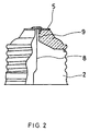
- the lead wire 8 was connected to the base eyelet 5 portion firmly and completely by using the conductive metal, and the eyelet hole portion appeared good and was closed sufficiently, as shown in FIG.
- the minimum outer diameter of the conductive metal piece to be supplied is equal to or larger than the diameter of the hole 9 of the eyelet.
- the minimum outer diameter of the conductive metal piece means an outer diameter defined from the viewpoint of whether or not it can pass though the hole 9.
- the conductive metal piece can be supplied to the base eyelet portion through the funnel shaped-holder from a stock container irregularly, the application of plasma welding work to an apparatus for capping a lamp of an automatic manufacturing machine for lamps does not interfere with the automatic manufacture.
- the lamp of the present invention is not limited to a regular lamp as described in the above example, and can be various incandescent lamps, a halogen lamp, a high-pressure discharge lamp or the like using an E-type base or other shaped-base.
- the material for the conductive metal piece is not limited to the materials described herein, and any materials can be used, as long as it does not interfere with the plasma arc welding work for connecting the lead wire and the base eyelet. Furthermore, any shape or size can be used, as long as it does not let the conductive metal piece fall down from the hole of the base eyelet to the inside of the base before welding.
- the holder with a funnel provided above the base eyelet of the present invention can be partially non-conductive, as long as it has conductivity necessary for plasma arc welding.
- the method for capping a lamp of the present invention can achieve complete and firm connection between the lead wire and the eyelet by plasma arc welding for the base eyelet and the lead wire, even if the diameter of hole of the base eyelet is excessively large relative to that of the lead wire. Moreover in the present invention, the hole of the base eyelet can be closed completely with a satisfactory appearance. Therefore, the present invention provides great practical advantages over the prior art. In addition, the present invention is suitable for automatic manufacture and provides high production efficiency.
Landscapes
- Engineering & Computer Science (AREA)
- Manufacturing & Machinery (AREA)
- Manufacture Of Electron Tubes, Discharge Lamp Vessels, Lead-In Wires, And The Like (AREA)
- Common Detailed Techniques For Electron Tubes Or Discharge Tubes (AREA)
Applications Claiming Priority (2)
| Application Number | Priority Date | Filing Date | Title |
|---|---|---|---|
| JP14208999A JP3578662B2 (ja) | 1999-05-21 | 1999-05-21 | 管球の口金付け方法 |
| JP14208999 | 1999-05-21 |
Publications (2)
| Publication Number | Publication Date |
|---|---|
| EP1054435A2 true EP1054435A2 (de) | 2000-11-22 |
| EP1054435A3 EP1054435A3 (de) | 2005-12-07 |
Family
ID=15307185
Family Applications (1)
| Application Number | Title | Priority Date | Filing Date |
|---|---|---|---|
| EP00110484A Withdrawn EP1054435A3 (de) | 1999-05-21 | 2000-05-17 | Verfahren zum Kapseln von Lampen |
Country Status (4)
| Country | Link |
|---|---|
| US (1) | US6554670B1 (de) |
| EP (1) | EP1054435A3 (de) |
| JP (1) | JP3578662B2 (de) |
| CN (1) | CN1333424C (de) |
Cited By (1)
| Publication number | Priority date | Publication date | Assignee | Title |
|---|---|---|---|---|
| EP1056111A3 (de) * | 1999-05-25 | 2005-12-14 | Matsushita Electric Industrial Co., Ltd. | Herstellungsverfahren von Lampen |
Families Citing this family (6)
| Publication number | Priority date | Publication date | Assignee | Title |
|---|---|---|---|---|
| DE10003434A1 (de) * | 2000-01-27 | 2001-08-02 | Patent Treuhand Ges Fuer Elektrische Gluehlampen Mbh | Verfahren zum Verbinden eines Stromzuführungsdrahtes mit einem Kontaktblech einer elektrischen Lampe |
| CN102015900B (zh) * | 2008-03-26 | 2012-11-07 | 陶氏康宁公司 | 硅氧烷组合物和有机发光二极管 |
| CN101728153B (zh) * | 2008-10-30 | 2011-09-07 | 普罗斯电器(江苏)有限公司 | 气体放电灯头冲孔装置 |
| TWI403669B (zh) * | 2010-12-23 | 2013-08-01 | Cal Comp Optical Electronics Suzhou Co Ltd | 燈具組裝機台 |
| CN110246748B (zh) * | 2018-12-26 | 2021-02-19 | 保定来福汽车照明集团有限公司 | 一种p21灯泡灯头与泡体的连接工艺 |
| CN110227870B (zh) * | 2018-12-26 | 2024-06-28 | 保定来福汽车照明集团有限公司 | 一种灯头焊泥造型工装 |
Family Cites Families (11)
| Publication number | Priority date | Publication date | Assignee | Title |
|---|---|---|---|---|
| US3849691A (en) * | 1972-12-08 | 1974-11-19 | Gen Electric | High intensity lamp containing arc extinguishing base |
| US3897124A (en) * | 1973-11-14 | 1975-07-29 | Gen Electric | Lamp base assembly |
| DD137992A1 (de) * | 1978-07-21 | 1979-10-03 | Becker Wolf Ruediger | Schweissverbindung zwischen den stromzufuehrungen und dem sockel elektrischer lampen |
| JPS5630247A (en) | 1979-08-20 | 1981-03-26 | Iwasaki Electric Co Ltd | Base for bulb and method of welding same to lead wires |
| DD148692A1 (de) * | 1980-01-22 | 1981-06-03 | Becker Wolf Ruediger | Verfahren und vorrichtung fuer schweissverbindungen zwischen duennblechen und draehten |
| JPS6273552A (ja) | 1985-09-27 | 1987-04-04 | 株式会社東芝 | 管球の製造方法 |
| JPH06275244A (ja) * | 1993-03-22 | 1994-09-30 | Toshiba Lighting & Technol Corp | 管球製造用溶接治具、管球製造方法および白熱電球 |
| US5306179A (en) * | 1993-04-09 | 1994-04-26 | General Electric Company | Lamp base and method of forming same |
| JPH08138631A (ja) | 1994-11-15 | 1996-05-31 | Origin Electric Co Ltd | 管球のアーク溶接装置及び溶接方法 |
| JPH08190867A (ja) | 1995-01-10 | 1996-07-23 | Origin Electric Co Ltd | 管球のアーク溶接方法及び溶接装置 |
| JPH10275602A (ja) | 1997-01-31 | 1998-10-13 | Toshiba Lighting & Technol Corp | 管球および照明器具 |
-
1999
- 1999-05-21 JP JP14208999A patent/JP3578662B2/ja not_active Expired - Fee Related
-
2000
- 2000-05-17 EP EP00110484A patent/EP1054435A3/de not_active Withdrawn
- 2000-05-18 US US09/574,465 patent/US6554670B1/en not_active Expired - Fee Related
- 2000-05-20 CN CNB001184938A patent/CN1333424C/zh not_active Expired - Fee Related
Non-Patent Citations (1)
| Title |
|---|
| None * |
Cited By (1)
| Publication number | Priority date | Publication date | Assignee | Title |
|---|---|---|---|---|
| EP1056111A3 (de) * | 1999-05-25 | 2005-12-14 | Matsushita Electric Industrial Co., Ltd. | Herstellungsverfahren von Lampen |
Also Published As
| Publication number | Publication date |
|---|---|
| JP2000331650A (ja) | 2000-11-30 |
| EP1054435A3 (de) | 2005-12-07 |
| CN1333424C (zh) | 2007-08-22 |
| JP3578662B2 (ja) | 2004-10-20 |
| US6554670B1 (en) | 2003-04-29 |
| CN1275794A (zh) | 2000-12-06 |
Similar Documents
| Publication | Publication Date | Title |
|---|---|---|
| US5286227A (en) | Arc tube and method for manufacturing the same | |
| US6554670B1 (en) | Method for capping lamps | |
| US7122953B2 (en) | High pressure discharge lamp and method of manufacturing an electrode feedthrough for such a lamp | |
| US2441257A (en) | Welding stud | |
| DE1278001B (de) | Halogenlampe | |
| EP1727179B1 (de) | Herstellungsverfahren von Lampen | |
| US2841690A (en) | Contact pin and method for fluorescent lamps | |
| US6081067A (en) | Plastic housing and screw base construction for compact fluorescent lamps and electrical operating units thereof | |
| KR102098696B1 (ko) | 잠호 저항 용접 방법 | |
| US4827189A (en) | Solder connection for an electrode of the gas discharge lamp and the method for manufacture | |
| US4607192A (en) | Pre-focussed incandescent lamps and method of assembling base thereof | |
| EP1273379A2 (de) | Verfahren zur Herstellung von Elektroden | |
| JP4056706B2 (ja) | 管球の製造方法 | |
| US4888519A (en) | Electric lamp and method of manufacturing same | |
| EP0229429B1 (de) | Elektrische Lampe und Verfahren zur Herstellung dieser Lampe | |
| US20050077809A1 (en) | Electric lamp | |
| CN213437735U (zh) | 焊条夹持装置 | |
| KR830000684B1 (ko) | 관구용 금속구 핀의 용접방법 | |
| JP3120271U (ja) | アルミ箔を介して封止した筒形ヒューズ | |
| US6111360A (en) | Fluorescent discharge lamp with overcurrent protection | |
| JP2002103073A (ja) | フィラメント溶接方法 | |
| JPH0945227A (ja) | 放電ランプ用給電構造 | |
| JP2001291466A (ja) | 管球および管球の製造方法 | |
| JP2004220914A (ja) | 冷陰極管のリード線接続法 | |
| DE1489328A1 (de) | Schmelzverbindung an einer elektrischen Entladungseinrichtung |
Legal Events
| Date | Code | Title | Description |
|---|---|---|---|
| PUAI | Public reference made under article 153(3) epc to a published international application that has entered the european phase |
Free format text: ORIGINAL CODE: 0009012 |
|
| AK | Designated contracting states |
Kind code of ref document: A2 Designated state(s): AT BE CH CY DE DK ES FI FR GB GR IE IT LI LU MC NL PT SE |
|
| AX | Request for extension of the european patent |
Free format text: AL;LT;LV;MK;RO;SI |
|
| RAP1 | Party data changed (applicant data changed or rights of an application transferred) |
Owner name: MATSUSHITA ELECTRIC INDUSTRIAL CO., LTD. |
|
| PUAL | Search report despatched |
Free format text: ORIGINAL CODE: 0009013 |
|
| RIC1 | Information provided on ipc code assigned before grant |
Ipc: 7H 01K 1/46 B Ipc: 7H 01K 3/16 B Ipc: 7H 01J 5/62 B Ipc: 7H 01J 9/24 A |
|
| AK | Designated contracting states |
Kind code of ref document: A3 Designated state(s): AT BE CH CY DE DK ES FI FR GB GR IE IT LI LU MC NL PT SE |
|
| AX | Request for extension of the european patent |
Extension state: AL LT LV MK RO SI |
|
| 17P | Request for examination filed |
Effective date: 20060216 |
|
| AKX | Designation fees paid |
Designated state(s): DE FR GB |
|
| APBN | Date of receipt of notice of appeal recorded |
Free format text: ORIGINAL CODE: EPIDOSNNOA2E |
|
| APBR | Date of receipt of statement of grounds of appeal recorded |
Free format text: ORIGINAL CODE: EPIDOSNNOA3E |
|
| APAF | Appeal reference modified |
Free format text: ORIGINAL CODE: EPIDOSCREFNE |
|
| RAP1 | Party data changed (applicant data changed or rights of an application transferred) |
Owner name: PANASONIC CORPORATION |
|
| APBT | Appeal procedure closed |
Free format text: ORIGINAL CODE: EPIDOSNNOA9E |
|
| GRAC | Information related to communication of intention to grant a patent modified |
Free format text: ORIGINAL CODE: EPIDOSCIGR1 |
|
| GRAP | Despatch of communication of intention to grant a patent |
Free format text: ORIGINAL CODE: EPIDOSNIGR1 |
|
| STAA | Information on the status of an ep patent application or granted ep patent |
Free format text: STATUS: THE APPLICATION IS DEEMED TO BE WITHDRAWN |
|
| 18D | Application deemed to be withdrawn |
Effective date: 20100707 |