EP1056587B1 - Technique de fabrication de corps flottants en resines synthetiques renforcees par des fibres continues et realises sur machine a bobiner - Google Patents
Technique de fabrication de corps flottants en resines synthetiques renforcees par des fibres continues et realises sur machine a bobiner Download PDFInfo
- Publication number
- EP1056587B1 EP1056587B1 EP99902593A EP99902593A EP1056587B1 EP 1056587 B1 EP1056587 B1 EP 1056587B1 EP 99902593 A EP99902593 A EP 99902593A EP 99902593 A EP99902593 A EP 99902593A EP 1056587 B1 EP1056587 B1 EP 1056587B1
- Authority
- EP
- European Patent Office
- Prior art keywords
- mandrel
- floating body
- process according
- manufactured
- winding
- Prior art date
- Legal status (The legal status is an assumption and is not a legal conclusion. Google has not performed a legal analysis and makes no representation as to the accuracy of the status listed.)
- Expired - Lifetime
Links
- 238000007667 floating Methods 0.000 title claims abstract description 66
- 238000000034 method Methods 0.000 title claims abstract description 44
- 238000004804 winding Methods 0.000 title claims description 38
- 229920003002 synthetic resin Polymers 0.000 title abstract description 3
- 239000000057 synthetic resin Substances 0.000 title abstract description 3
- 239000000835 fiber Substances 0.000 claims abstract description 43
- 238000004519 manufacturing process Methods 0.000 claims abstract description 40
- 238000009730 filament winding Methods 0.000 claims abstract description 10
- 229920005989 resin Polymers 0.000 claims description 25
- 239000011347 resin Substances 0.000 claims description 25
- 238000011282 treatment Methods 0.000 claims description 16
- 238000005520 cutting process Methods 0.000 claims description 15
- 239000000463 material Substances 0.000 claims description 15
- 238000007670 refining Methods 0.000 claims description 13
- 238000007711 solidification Methods 0.000 claims description 12
- 230000008023 solidification Effects 0.000 claims description 12
- 230000002787 reinforcement Effects 0.000 claims description 10
- 239000011248 coating agent Substances 0.000 claims description 8
- 238000000576 coating method Methods 0.000 claims description 8
- 238000005507 spraying Methods 0.000 claims description 8
- 239000006260 foam Substances 0.000 claims description 6
- 238000003801 milling Methods 0.000 claims description 6
- 238000003754 machining Methods 0.000 claims description 5
- 238000005470 impregnation Methods 0.000 claims description 4
- 229920006327 polystyrene foam Polymers 0.000 claims description 3
- 229920002994 synthetic fiber Polymers 0.000 claims description 3
- 238000005192 partition Methods 0.000 claims description 2
- 238000000227 grinding Methods 0.000 claims 4
- 238000005304 joining Methods 0.000 claims 3
- 238000004381 surface treatment Methods 0.000 claims 3
- 238000005498 polishing Methods 0.000 claims 2
- OKTJSMMVPCPJKN-UHFFFAOYSA-N Carbon Chemical compound [C] OKTJSMMVPCPJKN-UHFFFAOYSA-N 0.000 claims 1
- 229920000049 Carbon (fiber) Polymers 0.000 claims 1
- 229920006231 aramid fiber Polymers 0.000 claims 1
- 229910052799 carbon Inorganic materials 0.000 claims 1
- 239000011521 glass Substances 0.000 claims 1
- 239000006082 mold release agent Substances 0.000 claims 1
- KWGRBVOPPLSCSI-WPRPVWTQSA-N (-)-ephedrine Chemical compound CN[C@@H](C)[C@H](O)C1=CC=CC=C1 KWGRBVOPPLSCSI-WPRPVWTQSA-N 0.000 description 27
- 208000031968 Cadaver Diseases 0.000 description 19
- 239000002131 composite material Substances 0.000 description 8
- 239000003795 chemical substances by application Substances 0.000 description 4
- 230000003247 decreasing effect Effects 0.000 description 4
- 238000000465 moulding Methods 0.000 description 4
- 239000000243 solution Substances 0.000 description 4
- 241000195940 Bryophyta Species 0.000 description 3
- 241001125831 Istiophoridae Species 0.000 description 3
- 230000032798 delamination Effects 0.000 description 3
- 238000000151 deposition Methods 0.000 description 3
- 238000001802 infusion Methods 0.000 description 3
- 238000002347 injection Methods 0.000 description 3
- 239000007924 injection Substances 0.000 description 3
- 235000011929 mousse Nutrition 0.000 description 3
- 238000005070 sampling Methods 0.000 description 3
- 235000005921 Cynara humilis Nutrition 0.000 description 2
- 240000002228 Cynara humilis Species 0.000 description 2
- 241001080024 Telles Species 0.000 description 2
- 238000000429 assembly Methods 0.000 description 2
- 230000000712 assembly Effects 0.000 description 2
- 230000003416 augmentation Effects 0.000 description 2
- 238000009434 installation Methods 0.000 description 2
- 239000011505 plaster Substances 0.000 description 2
- 239000004033 plastic Substances 0.000 description 2
- 238000002360 preparation method Methods 0.000 description 2
- 238000004088 simulation Methods 0.000 description 2
- 229920001187 thermosetting polymer Polymers 0.000 description 2
- 240000007182 Ochroma pyramidale Species 0.000 description 1
- 230000002457 bidirectional effect Effects 0.000 description 1
- 238000004364 calculation method Methods 0.000 description 1
- 230000007547 defect Effects 0.000 description 1
- 238000005187 foaming Methods 0.000 description 1
- 230000001788 irregular Effects 0.000 description 1
- 238000005457 optimization Methods 0.000 description 1
- 238000006116 polymerization reaction Methods 0.000 description 1
- 238000011084 recovery Methods 0.000 description 1
- 239000002990 reinforced plastic Substances 0.000 description 1
- 239000012783 reinforcing fiber Substances 0.000 description 1
- 210000002345 respiratory system Anatomy 0.000 description 1
- 230000000717 retained effect Effects 0.000 description 1
- 239000007921 spray Substances 0.000 description 1
- 239000012209 synthetic fiber Substances 0.000 description 1
- XLYOFNOQVPJJNP-UHFFFAOYSA-N water Substances O XLYOFNOQVPJJNP-UHFFFAOYSA-N 0.000 description 1
Images


Classifications
-
- B—PERFORMING OPERATIONS; TRANSPORTING
- B29—WORKING OF PLASTICS; WORKING OF SUBSTANCES IN A PLASTIC STATE IN GENERAL
- B29C—SHAPING OR JOINING OF PLASTICS; SHAPING OF MATERIAL IN A PLASTIC STATE, NOT OTHERWISE PROVIDED FOR; AFTER-TREATMENT OF THE SHAPED PRODUCTS, e.g. REPAIRING
- B29C70/00—Shaping composites, i.e. plastics material comprising reinforcements, fillers or preformed parts, e.g. inserts
- B29C70/04—Shaping composites, i.e. plastics material comprising reinforcements, fillers or preformed parts, e.g. inserts comprising reinforcements only, e.g. self-reinforcing plastics
- B29C70/28—Shaping operations therefor
- B29C70/30—Shaping by lay-up, i.e. applying fibres, tape or broadsheet on a mould, former or core; Shaping by spray-up, i.e. spraying of fibres on a mould, former or core
- B29C70/34—Shaping by lay-up, i.e. applying fibres, tape or broadsheet on a mould, former or core; Shaping by spray-up, i.e. spraying of fibres on a mould, former or core and shaping or impregnating by compression, i.e. combined with compressing after the lay-up operation
- B29C70/347—Shaping by lay-up, i.e. applying fibres, tape or broadsheet on a mould, former or core; Shaping by spray-up, i.e. spraying of fibres on a mould, former or core and shaping or impregnating by compression, i.e. combined with compressing after the lay-up operation combined with compressing after the winding of lay-ups having a non-circular cross-section, e.g. flat spiral windings
-
- B—PERFORMING OPERATIONS; TRANSPORTING
- B29—WORKING OF PLASTICS; WORKING OF SUBSTANCES IN A PLASTIC STATE IN GENERAL
- B29C—SHAPING OR JOINING OF PLASTICS; SHAPING OF MATERIAL IN A PLASTIC STATE, NOT OTHERWISE PROVIDED FOR; AFTER-TREATMENT OF THE SHAPED PRODUCTS, e.g. REPAIRING
- B29C53/00—Shaping by bending, folding, twisting, straightening or flattening; Apparatus therefor
- B29C53/56—Winding and joining, e.g. winding spirally
- B29C53/566—Winding and joining, e.g. winding spirally for making tubular articles followed by compression
-
- B—PERFORMING OPERATIONS; TRANSPORTING
- B29—WORKING OF PLASTICS; WORKING OF SUBSTANCES IN A PLASTIC STATE IN GENERAL
- B29C—SHAPING OR JOINING OF PLASTICS; SHAPING OF MATERIAL IN A PLASTIC STATE, NOT OTHERWISE PROVIDED FOR; AFTER-TREATMENT OF THE SHAPED PRODUCTS, e.g. REPAIRING
- B29C70/00—Shaping composites, i.e. plastics material comprising reinforcements, fillers or preformed parts, e.g. inserts
- B29C70/04—Shaping composites, i.e. plastics material comprising reinforcements, fillers or preformed parts, e.g. inserts comprising reinforcements only, e.g. self-reinforcing plastics
- B29C70/28—Shaping operations therefor
- B29C70/54—Component parts, details or accessories; Auxiliary operations, e.g. feeding or storage of prepregs or SMC after impregnation or during ageing
- B29C70/545—Perforating, cutting or machining during or after moulding
-
- B—PERFORMING OPERATIONS; TRANSPORTING
- B63—SHIPS OR OTHER WATERBORNE VESSELS; RELATED EQUIPMENT
- B63B—SHIPS OR OTHER WATERBORNE VESSELS; EQUIPMENT FOR SHIPPING
- B63B32/00—Water sports boards; Accessories therefor
- B63B32/57—Boards characterised by the material, e.g. laminated materials
-
- B—PERFORMING OPERATIONS; TRANSPORTING
- B63—SHIPS OR OTHER WATERBORNE VESSELS; RELATED EQUIPMENT
- B63B—SHIPS OR OTHER WATERBORNE VESSELS; EQUIPMENT FOR SHIPPING
- B63B5/00—Hulls characterised by their construction of non-metallic material
- B63B5/24—Hulls characterised by their construction of non-metallic material made predominantly of plastics
-
- B—PERFORMING OPERATIONS; TRANSPORTING
- B29—WORKING OF PLASTICS; WORKING OF SUBSTANCES IN A PLASTIC STATE IN GENERAL
- B29L—INDEXING SCHEME ASSOCIATED WITH SUBCLASS B29C, RELATING TO PARTICULAR ARTICLES
- B29L2031/00—Other particular articles
- B29L2031/30—Vehicles, e.g. ships or aircraft, or body parts thereof
- B29L2031/3067—Ships
- B29L2031/307—Hulls
-
- B—PERFORMING OPERATIONS; TRANSPORTING
- B63—SHIPS OR OTHER WATERBORNE VESSELS; RELATED EQUIPMENT
- B63B—SHIPS OR OTHER WATERBORNE VESSELS; EQUIPMENT FOR SHIPPING
- B63B2231/00—Material used for some parts or elements, or for particular purposes
- B63B2231/40—Synthetic materials
- B63B2231/52—Fibre reinforced plastics materials
Definitions
- the invention relates to the technique for manufacturing floating bodies made of resins. synthetic fibers reinforced with continuous fibers and produced on a winding.
- the floating bodies made of fiber-reinforced synthetic resins are traditionally made by contact molding of cut fibers and impregnated with resin, on female molds or master models in several parts.
- the cutting, removal and impregnation phases, except in the case of prepreg fibers, are generally carried out manually.
- the fibers are in the form of unidirectional, bidirectional or three-way or in the form of short fibers randomly oriented.
- the contact impregnation of the fibers does not allow the use of certain resins with high characteristics, harmful through the respiratory tract or on contact with the skin.
- filament winding which consists of winding on a mandrel having the shape of the desired part, continuous fibers impregnated with resin arranged in directions determined in advance.
- the continuous fibers are wound on the one hand in the direction of the principal stresses in a homogeneous way, on the other hand locally in highly constrained areas.
- filament winding concerns winding structures with decreasing sections, usual case in floating devices.
- the difficulty is to respect the orientations of the fibers and the defined thicknesses for the mechanical strength of the structure.
- the fibers can slide on the mandrel, and the extra thicknesses obtained in small sections do not correspond to thicknesses desired.
- the structure obtained is not symmetrical with respect to to the plane of symmetry of the mandrel.
- the document FR 1 590 718 A describes a "manufacturing process of any shape structure, the machine for the implementation of said process and the structures produced by said process ”.
- the invention can provide a solution to the drawbacks encountered currently in the production of floating bodies in composite materials synthetics, making them with continuous fibers on a winding, after solving the problems posed by this manufacturing process currently unsuitable for the production of such products.
- the invention relates in particular to a method of manufacturing a floating body such as a boat hull or part of such a hull defined in claims and which comprises at least one filament winding step.
- a second object of the invention is to obtain mandrels intended for the implementation of the method according to the claims.
- a third object of the invention is the apparatus intended for implementing the method according to the claims.
- sampling defines the thickness and number of layers, the orientation of the fibers in the different floating body areas as well as orientation, dimensions and locations of the various reinforcements.
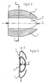
- a first shaped mandrel 1 draft is carried out.
- This first mandrel 1 is shown schematically in Figure 1.
- the rings 2 are threaded, glued and tightened longitudinally, for example on two axes 3 allowing the rotational drive of the whole.
- This blank-shaped mandrel 1 is then mounted on the winding apparatus to undergo a refining treatment of its exterior shape.
- a finishing plaster, for example sprayed by a spraying system mounted on the tool holder 5 is applied to the entire mandrel 1.
- Sanding and buffing operations can then be performed with sanders and polishers mounted on the tool holder 5.
- This mandrel 1 can also be produced from an existing floating body, itself optionally carried out according to the method of the present invention. The manufacture and preparation of the first mandrel 1 are then completed.
- a release agent and a finishing coating constituting the internal surface of the countermold 7 are projected onto the entire mandrel 1 by a system of spraying mounted on the tool holder 5.
- the winding is carried out by orienting the fibers so as to obtain the sampling specific to the countermold 7, using a comb 6 mounted on the tool holder 5, which allows the guiding the fibers impregnated with resin.
- the countermold 7 has been cut after solidification, by example in its longitudinal plane of symmetry, using a cutting tool, for example a disc saw, mounted on the tool holder 5.
- a cutting tool for example a disc saw
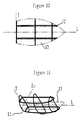
- a second mandrel 8 has substantially the internal shape of the body floating to manufacture 11. It can have on the one hand longitudinal grooves 9 and transverse to wind and have structural reinforcements and fittings, on the other hand rigid elements to its ends, allowing the installation of raised devices 10, like this is shown schematically in Figure 7. Other devices such as non-slip products can be placed on the mandrel 8 to increase the adhesion of the fibers which will cover it.
- This mandrel 8 is then mounted on the winding device to undergo possibly a refining treatment of its external surface. For example, a release agent sprayed by a spray system mounted on the door tool 5, is then applied to all or part of the mandrel 8. Manufacturing and the preparation of the second mandrel 8 are then completed.
- the floating body is wound using a comb mounted on the tool holder, which allows the fibers to be guided. It begins for example with winding continuous fibers in grooves, which can be completely filled to obtain a monolithic reinforcement structure, or part by inserting a core during winding, for example in foam P.V.C. or balsa, to obtain a so-called sandwich reinforcement structure.
- the winding of the rest of the form 8 is carried out by depositing the fibers so as to obtain the sampling defined during the design, symmetrical with respect to the axis of symmetry of the floating body.
- the fibers are mainly oriented at 45 ° and 0 ° by relation to the plane of symmetry of the floating body.
- the fibers are wound on a first trajectory at 45 ° relative to the axis of rotation of the mandrel up to a so-called turning area, located between two cross sections of the mandrel and defined in the design of the sailboat.
- the fibers are deposited, thanks to winding aids such as spikes or non-slip products, so as to join the plane of symmetry of the sailboat. They follow then a second trajectory symmetrical to the first trajectory, by relation to the plane of symmetry.
- the reversal zones must be located in zones strongly constrained such as the bottom of the hull between the keel and the bow of the sailboat, and at the ends of the floating body.
- the turning areas are located at the ends where the aid is arranged to the winding such as spikes.
- a release agent and a finishing coating are applied to the internal part of the countermold 7.
- the coiled floating body 11 is clamped between the second mandrel 8 and the two elements of the countermold 7.
- the countermold 7 can be put in place after slightly reducing the volume of the mandrel 8 by deflation.
- the materials of the floating body 11 are then pressed against the internal surface of the countermold 7, increasing the volume of the mandrel 8 by inflation, in order to obtain on the one hand an optimal cohesion between the materials of the floating body 11 and the internal surface of the countermold 7, on the other hand a rate resin determined.
- This variation in volume can also be obtained mechanically, in particular in the case where the second mandrel 8 has the form of two identical floating devices.
- This can also include the infusion or injection of resin or the use of an expansive resin, especially in the case where the volume of the second mandrel 8 does not vary.
- the floating body 11 can be cut, for example using a disc saw mounted on the tool holder 5, in particular in the case of a sailboat for passage and the assembly of equipment such as masts, keel, chainlocks, deckhouses or for evacuation of the mandrel 8.
- the outer surface of the floating body 11 may undergo a refining treatment, such as sanding and spraying a finishing plaster, using specific tools mounted on the tool holder 5.
- the mandrel can be made of rigid elements allowing to wind only defined reinforcements.
- the device according to the invention is particularly suitable for manufacturing in series or individually of at least part of floating bodies, such as reinforcements, deck, hull of floating, motor or sailing, monohulls or multihulls, professional, racing, exploring, or custom amateur.
- floating bodies such as reinforcements, deck, hull of floating, motor or sailing, monohulls or multihulls, professional, racing, exploring, or custom amateur.
Landscapes
- Engineering & Computer Science (AREA)
- Mechanical Engineering (AREA)
- Chemical & Material Sciences (AREA)
- Combustion & Propulsion (AREA)
- Ocean & Marine Engineering (AREA)
- Composite Materials (AREA)
- Moulding By Coating Moulds (AREA)
- Reinforced Plastic Materials (AREA)
- Laminated Bodies (AREA)
Description
- réaliser un premier mandrin en forme d'ébauche, présentant sensiblement la forme externe du corps flottant à fabriquer ;
- monter ce premier mandrin sur un appareil à bobiner, et éventuellement lui faire subir un traitement d'affinage de sa forme externe ;
- recouvrir ce premier mandrin au moins en partie, par bobinage ou enroulement filamentaire de fibres imprégnées de résine afin d'obtenir un moule extérieur ou contremoule dont la surface interne subira un traitement, tel que revêtement d'un démoulant et/ou d'enduit de finition constituant la surface externe du corps flottant à fabriquer ;
- après solidification, découper le contremoule en au moins deux parties démoulables, par exemple suivant un plan de symétrie longitudinal ;
- réaliser un deuxième mandrin en forme d'ébauche, présentant sensiblement la forme interne du corps flottant à fabriquer ;
- monter ce deuxième mandrin sur un appareil à bobiner, et éventuellement lui faire subir un traitement d'affinage de sa forme externe ;
- recouvrir ce deuxième mandrin au moins en partie, par bobinage ou enroulement filamentaire avec ou sans imprégnation de résine, pour obtenir un corps bobiné qui sera le corps flottant ;
- mettre sous pression les matériaux du corps flottant entre le deuxième mandrin et le contremoule ;
- après solidification des matériaux du corps flottant, telle que polymérisation, dégager le contremoule et/ou faire subir un traitement d'affinage au corps flottant, découper au moins une réservation dans ce dernier, par exemple pour le passage ou l'assemblage d'équipements tels que mâts, quille, rouf ou analogues et/ou pour l'évacuation d'au moins une partie du mandrin.
- Les traitements d'affinage des surfaces externes des mandrins prévoient la mise en place de dispositifs d'aide à l'enroulement, de matière et de dimensions convenables, tels que picots et/ou produits anti-dérapants, permettant une augmentation de l'adhérence entre le mandrin et les fibres qui viendront le recouvrir.
- L'étape de recouvrement du premier mandrin comporte au moins une phase de dépose d'au moins une fibre continue imprégnée ou non de résine, suivant des directions définies lors de la conception du contremoule. Les trajectoires des fibres sont symétriques par rapport à au moins un plan de symétrie du premier mandrin, avec des zones de retournement dans différentes sections du mandrin afin d'obtenir au moins une couche de fibres dont les épaisseurs sont définies à la conception du contremoule.
- L'étape de recouvrement du deuxième mandrin comporte au moins une phase de dépose d'au moins une fibre continue imprégnée ou non de résine, suivant des directions définies lors de la conception du corps flottant. Les trajectoires des fibres sont symétriques par rapport à au moins un plan de symétrie du deuxième mandrin, avec des zones de retournement dans différentes sections du mandrin afin d'obtenir au moins une couche de fibres dont les épaisseurs sont définies à la conception du corps flottant.
- L'étape de mise sous pression des matériaux du corps flottant prévoit une augmentation du volume du deuxième mandrin et/ou une infusion et/ou une Injection de résine et/ou une expansion de résine telle que résine moussante afin d'obtenir d'une part un état de surface identique à celui de la surface interne du contremoule, d'autre part un taux de résine déterminé.
- la figure 1 est une vue en plan schématique du premier mandrin en forme d'ébauche,
- la figure 2 est une vue en coupe de face d'un élément en mousse synthétique du premier mandrin, vue suivant la ligne 1-1 de la figure 1,
- la figure 3 est une vue en plan schématique du premier mandrin monté sur l'appareil à bobiner en cours d'usinage,
- la figure 4 est une vue en plan schématique du premier mandrin monté sur l'appareil à bobiner en cours d'enroulement du contremoule,
- la figure 5 est une vue en plan schématique du premier mandrin et du contremoule découpé en deux parties symétriques en cours de démoulage,
- la figure 6 est une vue en coupe de face du premier mandrin et du contremoule découpé en deux parties symétriques en cours de démoulage, vue suivant la ligne 2-2 de la figure 5,
- la figure 7 est une vue en plan schématique du deuxième mandrin avec des rainures transversales suivant la direction T et longitudinales suivant la direction L, constitué soit à partir d'un élément gonflable, soit à partir d'éléments en mousse synthétique,
- la figure 8 est une vue en élévation latérale du deuxième mandrin dans le cas où il a la forme de deux engins flottants identiques réunis par leur partie supérieure,
- la figure 9 est une vue en coupe de face du deuxième mandrin dans le cas où il a la forme de deux engins flottants identiques réunis par leur partie supérieure, vue suivant la ligne 3-3 de la figure 8,
- la figure 10 est une vue en plan schématique du deuxième mandrin monté sur l'appareil à bobiner en cours de bobinage des renforts du corps flottant,
- la figure 11 est une vue en plan schématique du corps flottant bobiné et des deux éléments du contremoule en cours d'assemblage, en vue de la mise sous pression des matériaux du corps flottant,
- la figure 12 est une vue en coupe de face du corps flottant bobiné et des deux éléments du contremoule en cour d'assemblage, en vue de la mise sous pression des matériaux du corps flottant, vue suivant la ligne 4-4 de la figure 11,
- la figure 13 est une vue en plan schématique d'une structure bobinée seule.
- La figure 14 est une vue en perspective d'une structure bobinée seule.
- soit à partir d'un élément gonflable,
- soit, de manière similaire au premier mandrin 1, à partir d'éléments en mousse synthétique usinés, possédant éventuellement des sections intermédiaires placées entre ces éléments, par exemple des plaques en sandwich destinées à rester dans le corps flottant comme cloisons de structure,
- soit à partir d'éléments, par exemple en matériaux composites synthétiques, correspondant à la forme de deux corps flottants identiques réunis par leur partie supérieure, par exemple deux coques de voiliers accolées par leur pont comme le montrent la figure 8 et la figure 9.
- la production est optimisée et entièrement automatisée, grâce à l'emploi de logiciels de conception, de calculs par éléments finis, de simulation d'enroulement et de programmation de commande numérique. L'appareil à bobiner devient un centre automatisé d'usinage, de pulvérisation, de bobinage et de découpage. Ainsi, le risque de non conformité est limité, d'une part grâce à l'automatisation qui garantit la reproductibilité du produit fabriqué, d'autre part grâce à la réalisation des différentes opérations par l'intermédiaire d'un unique porte-outil.
- le produit fini possède des caractéristiques mécaniques élevées d'une part grâce à l'approche numérique qui permet une optimisation, d'autre part grâce à la solidification du composite avec des fibres contraintes et continues. De plus, le taux de résine du composite est parfaitement maítrisé en cours de fabrication et reste relativement faible par rapport à celui obtenu par moulage par contact. Dans le cas d'un voilier où le pont et la coque sont enroulés en même temps, les fibres étant continues sur toute la circonférence du voilier, la rigidité de la structure est augmentée et les risques de délaminage diminués.
- le positionnement des appendices et de l'accastillage du corps flottant est beaucoup plus précis grâce au découpage automatisé, qui élimine les défauts actuels de symétrie.
- le coût de la fibre continue présentée sous forme de fils en bobines ou pelotes est le plus économique.
Claims (21)
- Procédé de fabrication de corps flottants (11), tels que coque de bateau ou partie d'une telle coque, caractérisé en ce qu'il comporte la combinaison d'étapes prévoyant de :réaliser un premier mandrin en forme d'ébauche (1), présentant sensiblement la forme externe du corps flottant à fabriquer (11);monter le mandrin (1) sur un appareil à bobiner, et éventuellement lui faire subir un traitement d'affinage de sa forme externe ;recouvrir le premier mandrin (1) au moins en partie, par bobinage ou enroulement filamentaire de fibres imprégnées de résine afin d'obtenir un moule extérieur ou contremoule (7) dont la surface interne subira un traitement, tel que revêtement d'un démoulant et/ou d'enduit de finition constituant la surface externe du corps flottant à fabriquer ;après solidification, découper le contremoule (7) en au moins deux parties démoulables, par exemple suivant un plan de symétrie longitudinal ;réaliser un deuxième mandrin en forme d'ébauche (8), présentant sensiblement la forme interne du corps flottant à fabriquer (11) ;monter le deuxième mandrin (8) sur un appareil à bobiner, et éventuellement lui faire subir un traitement d'affinage de sa forme externe ;recouvrir le deuxième mandrin (8) au moins en partie, par bobinage ou enroulement filamentaire avec ou sans imprégnation de résine, pour obtenir un corps bobiné qui sera le corps flottant (11);mettre sous pression les matériaux du corps flottant entre le deuxième mandrin (8) et le contremoule (7) ;après solidification des matériaux du corps flottant (11), telle que polymérisation, dégager le contremoule (7) et/ou faire subir un traitement d'affinage au corps flottant (11), découper au moins une réservation dans ce dernier, par exemple pour le passage ou l'assemblage d'équipements tels que mâts, quille, rouf ou analogues et/ou pour l'évacuation d'au moins une partie du mandrin (8).
- Procédé selon la revendication 1 caractérisé en ce que l'étape de réalisation du premier mandrin (1) comporte une phase d'assemblage d'éléments (2) en matière synthétique telle que mousse polystyrène et/ou une phase de gonflage d'un élément de ce premier mandrin (1).
- Procédé selon l'une des revendications 1 à 2, caractérisé en ce que le traitement d'affinage de la forme externe du premier mandrin (1) prévoit un ponçage et/ou usinage tels que fraisage et/ou tournage et un traitement de surface tel que revêtement d'un démoulant et d'enduit de finition et la mise en place de dispositifs, de matière et de dimensions convenables tels que des picots et/ou des produits antidérapants, permettant une augmentation de l'adhérence entre le mandrin et les fibres qui viendront le recouvrir.
- Procédé selon l'une des revendications 1 à 3 caractérisé en ce que l'étape de recouvrement du premier mandrin (1) comporte une phase de liaison du contremoule à fabriquer (7) à au moins un organe de structure tel que renfort et/ou âme sandwich.
- Procédé selon l'une des revendications 1 à 4 caractérisé en ce que l'étape de recouvrement du premier mandrin (1) comporte une phase de dépose d'au moins une fibre continue imprégnée ou non de résine, suivant des directions prédéfinies lors de la conception du contremoule (7), afin d'obtenir au moins une couche de fibres dont chaque trajectoire possède un plan de symétrie confondu avec un plan de symétrie du premier mandrin (1), avec des zones de retournement situées entre différentes sections transversales du mandrin.
- Procédé selon l'une des revendications 1 à 5, caractérisé en ce que les étapes de découpage du contremoule (7) sont réalisées par montage sur l'appareil à bobiner d'un outil de découpe tel que fraise, disque ou système à projection de particule dit « laser », ce découpage étant par exemple réalisé suivant au moins un plan longitudinal, ou transversal ou en élévation.
- Procédé selon l'une des revendications 1 à 6 caractérisé en ce que le deuxième mandrin (8) est réalisé de manière similaire au premier mandrin (1), par exemple par assemblage d'éléments en matière synthétique telle que mousse polystyrène prévoyant l'interposition d'au moins un organe de structure tel que cloison, et/ou par gonflage d'au moins un élément de ce mandrin (8).
- Procédé selon la revendication 1 à 7, caractérisé en ce que le traitement d'affinage de la surface externe du deuxième mandrin (8) prévoit un ponçage et/ou usinage tels que fraisage et/ou tournage et un traitement de surface tel que revêtement d'un démoulant et d'enduit de finition et la mise en place de dispositifs, de matière et de dimensions convenables tels que des picots et/ou des produits antidérapants, permettant une augmentation de l'adhérence entre le mandrin (8) et les fibres qui viendront le recouvrir.
- Procédé selon l'une des revendications 1 à 8 caractérisé en ce que l'étape de recouvrement du deuxième mandrin (8) comporte une phase de liaison du corps flottant à fabriquer (11) à au moins un organe de structure tel que renfort et/ou support d'accastillage et/ou âme sandwich.
- Procédé selon l'une des revendications 1 à 9 caractérisé en ce que l'étape de recouvrement du deuxième mandrin (8) comporte une phase de dépose d'au moins une fibre continue imprégnée ou non de résine, suivant des directions prédéfinies lors de la conception du corps flottant, afin d'obtenir au moins une couche de fibres dont chaque trajectoire possède un plan de symétrie confondu avec un plan de symétrie du deuxième mandrin (8), avec des zones de retournement situées entre différentes sections transversales du mandrin.
- Procédé selon l'une des revendications 1 à 10, caractérisé en ce que l'étape de mise sous pression des matériaux du corps flottant (11) prévoit une augmentation du volume du deuxième mandrin (8) et/ou une injection ou infusion de résine et/ou l'expansion d'une résine moussante afin d'obtenir d'une part un état de surface identique à celui de la surface interne du contremoule (7), d'autre part un taux de résine déterminé.
- Procédé selon l'une des revendications 1 à 11, caractérisé en ce que les étapes de découpage du corps flottant (11) sont réalisées par montage sur l'appareil à bobiner d'un outil de découpe tel que fraise, disque ou système à projection de particule dit « laser », découpage qui est par exemple réalisé suivant au moins un plan longitudinal, ou transversal ou en élévation et qui comporte au moins une phase de découpe de réservations par exemple pour le passage et/ou l'assemblage d'équipements tels que mâts, quille, cadènes, rouf ou analogues, et/ou pour l'évacuation d'au moins une partie du deuxième mandrin (8).
- Procédé selon l'une des revendications 1 à 12, caractérisé en ce que le traitement d'affinage de la surface externe du corps flottant (11) prévoit un ponçage et/ou lustrage et/ou un traitement de surface tel que revêtement d'enduit de finition.
- Mandrin (1) destiné à la mise en oeuvre d'un procédé selon l'une des revendications 1 à 13, caractérisé en ce qu'il se compose d'anneaux en mousse synthétique (2) assemblés en forme d'ébauche présentant la forme externe du corps flottant à fabriquer (11).
- Mandrin (8) destiné à la mise en oeuvre d'un procédé selon l'une des revendications 1 à 13, caractérisé en ce qu'il se compose d'anneaux en mousse synthétique (2) assemblés et/ou d'au moins un élément gonflable en forme d'ébauche présentant sensiblement la forme interne du corps flottant à fabriquer (11).
- Mandrin (8) ou (1) selon les revendications 14 ou 15, caractérisé en ce qu'il possède des rainures (9), par exemple longitudinales et transversales et/ou des dispositifs en relief (10), permettant de bobiner et/ou de disposer au moins un organe de structure tel que renfort et/ou support d'accastillage.
- Appareil de fabrication d'un corps flottant (11) destiné à la mise en oeuvre d'un procédé selon l'une des revendications 1 à 13, sur lequel est monté un mandrin (8) ou (1) selon l'une des revendications 14 à 16, caractérisé en ce que cet appareil possède un axe asservi qui entraíne le mandrin (8) ou (1) en rotation et un porte-outil (5) asservi dans trois axes de translation, le porte-outil (5) étant prévu pour recevoir des outils de découpe tels que fraise (4), disque ou système à projection de particules dit « laser », pour recevoir aussi des outils de projection de produits tels qu'enduit de finition et agent démoulant, et pour recevoir encore des outils de ponçage et lustrage.
- Appareil de fabrication d'un corps selon la revendication 17, caractérisé en ce que le porte-outil (5) est prévu pour recevoir aussi une tête de dépose par exemple de type peigne (6) ou oeillet possédant au moins un degré de liberté en rotation afin de déposer sur le mandrin (8) ou (1) au moins une fibre continue telle que fibre de verre et/ou d'aramide.
- Corps flottant (11) caractérisé en ce qu'il se compose d'au moins une partie de coque fabriquée par un procédé selon l'une des revendications 1 à 13.
- Corps flottant (11) caractérisé en ce qu'il se compose d'au moins une partie de pont fabriquée par un procédé selon l'une des revendications 1 à 13.
- Engin flottant (11), tel que bateau de plaisance et/ou de compétition et/ou professionnel, caractérisé en ce qu'il se compose d'au moins une partie de coque et/ou de pont fabriquées par un procédé selon l'une des revendications 1 à 13.
Applications Claiming Priority (4)
| Application Number | Priority Date | Filing Date | Title |
|---|---|---|---|
| FR9801575A FR2774325B1 (fr) | 1998-02-05 | 1998-02-05 | Procede de fabrication de corps flottants et embarcations nautiques mandrins et appareils pour cette fabrication |
| FR9801575 | 1998-02-05 | ||
| FR1575000 | 1998-02-05 | ||
| PCT/FR1999/000243 WO1999039897A1 (fr) | 1998-02-05 | 1999-02-04 | Technique de fabrication de corps flottants en resines synthetiques renforcees par des fibres continues et realises sur machine a bobiner |
Publications (2)
| Publication Number | Publication Date |
|---|---|
| EP1056587A1 EP1056587A1 (fr) | 2000-12-06 |
| EP1056587B1 true EP1056587B1 (fr) | 2002-07-31 |
Family
ID=9522814
Family Applications (1)
| Application Number | Title | Priority Date | Filing Date |
|---|---|---|---|
| EP99902593A Expired - Lifetime EP1056587B1 (fr) | 1998-02-05 | 1999-02-04 | Technique de fabrication de corps flottants en resines synthetiques renforcees par des fibres continues et realises sur machine a bobiner |
Country Status (15)
| Country | Link |
|---|---|
| US (1) | US6490990B1 (fr) |
| EP (1) | EP1056587B1 (fr) |
| AT (1) | ATE221451T1 (fr) |
| AU (1) | AU752960B2 (fr) |
| CA (1) | CA2319685A1 (fr) |
| DE (1) | DE69902357T2 (fr) |
| DK (1) | DK1056587T3 (fr) |
| ES (1) | ES2181389T3 (fr) |
| FR (1) | FR2774325B1 (fr) |
| NO (1) | NO20003970L (fr) |
| NZ (1) | NZ506021A (fr) |
| PL (1) | PL342163A1 (fr) |
| PT (1) | PT1056587E (fr) |
| SK (1) | SK11372000A3 (fr) |
| WO (1) | WO1999039897A1 (fr) |
Families Citing this family (29)
| Publication number | Priority date | Publication date | Assignee | Title |
|---|---|---|---|---|
| FR2882681B1 (fr) * | 2005-03-03 | 2009-11-20 | Coriolis Composites | Tete d'application de fibres et machine correspondante |
| DK176526B1 (da) | 2006-10-20 | 2008-07-14 | Falck Schmidt Defence Systems | Metode til fremstilling af et fartöj indeholdende kulfiber |
| FR2912680B1 (fr) * | 2007-02-21 | 2009-04-24 | Coriolis Composites Sa | Procede et dispositif de fabrication de pieces en materiau composite, en particulier de troncons de fuselage d'avion |
| FR2912953B1 (fr) * | 2007-02-28 | 2009-04-17 | Coriolis Composites Sa | Machine d'application de fibres avec tubes flexibles d'acheminement de fibres |
| FR2913366B1 (fr) * | 2007-03-06 | 2009-05-01 | Coriolis Composites Sa | Tete d'application de fibres avec systemes de coupe et de blocage de fibres particuliers |
| FR2913365B1 (fr) * | 2007-03-06 | 2013-07-26 | Coriolis Composites Attn Olivier Bouroullec | Tete d'application de fibres avec systemes de coupe de fibres particuliers |
| FR2943943A1 (fr) * | 2009-04-02 | 2010-10-08 | Coriolis Composites | Procede et machine pour l'application d'une bande de fibres sur des surfaces convexes et/ou avec aretes |
| FR2948059B1 (fr) * | 2009-07-17 | 2011-08-05 | Coriolis Composites | Machine d'application de fibres avec rouleau de compactage transparent au rayonnement du systeme de chauffage |
| FR2948058B1 (fr) * | 2009-07-17 | 2011-07-22 | Coriolis Composites | Machine d'application de fibres comprenant un rouleau de compactage souple avec systeme de regulation thermique |
| DE102010008711A1 (de) * | 2010-02-19 | 2011-08-25 | GKN Aerospace Services Limited, Isle of Wight | Verfahren und Anordnung zur Herstellung eines einstückigen Hohlprofilbauteils mit Faserverbundwerkstoff |
| GB201223001D0 (en) * | 2012-12-20 | 2013-01-30 | Williams Hybrid Power Ltd | Magnetically loaded composite rotor and methods of making the same |
| FR3005599B1 (fr) * | 2013-05-15 | 2015-09-18 | Airbus Operations Sas | Procede de realisation d'une preforme de fibres par enroulement et outillage pour mettre en oeuvre ledit procede |
| WO2014193505A1 (fr) * | 2013-05-31 | 2014-12-04 | United Technologies Corporation | Fabrication de composant continu renforcé de fibres |
| FR3034338B1 (fr) | 2015-04-01 | 2017-04-21 | Coriolis Composites | Tete d'application de fibres avec rouleau d'application particulier |
| FR3043010B1 (fr) | 2015-10-28 | 2017-10-27 | Coriolis Composites | Machine d'application de fibres avec systemes de coupe particuliers |
| FR3048373B1 (fr) | 2016-03-07 | 2018-05-18 | Coriolis Group | Procede de realisation de preformes avec application d'un liant sur fibre seche et machine correspondante |
| WO2017219058A1 (fr) * | 2016-06-22 | 2017-12-28 | Blair Nicholas William | Agencement de planche et procédé associé |
| CN106239933A (zh) * | 2016-08-31 | 2016-12-21 | 江苏佼燕船舶设备有限公司 | 救生艇艇壳真空制备方法 |
| FR3056438B1 (fr) | 2016-09-27 | 2019-11-01 | Coriolis Group | Procede de realisation de pieces en materiau composite par impregnation d'une preforme particuliere. |
| US11383453B2 (en) * | 2017-01-12 | 2022-07-12 | Swift IP, LLC | Methods of repairing and waterproofing articles |
| FR3070623B1 (fr) | 2017-09-04 | 2020-10-09 | Coriolis Composites | Procede de realisation d’une piece en materiau composite par aiguilletage oriente d’une preforme |
| CN111196045B (zh) * | 2018-11-19 | 2021-10-15 | 航天特种材料及工艺技术研究所 | 适用于中空结构的整体缠绕成型方法及中空结构 |
| CN109955496B (zh) * | 2019-04-23 | 2023-07-18 | 河南科技大学 | 一种纤维管编织用组合芯轴 |
| US11014291B1 (en) * | 2020-02-20 | 2021-05-25 | Thermwood Corporation | Methods and systems for producing boat molds by additive manufacturing |
| CN111890705B (zh) * | 2020-03-26 | 2022-11-04 | 中国运载火箭技术研究院 | 卫星支架模具 |
| WO2021260953A1 (fr) * | 2020-06-26 | 2021-12-30 | 日立Astemo株式会社 | Procédé de production d'un tube en résine renforcée par des fibres |
| CN114304094B (zh) * | 2021-12-22 | 2022-11-04 | 岳西县碧水行渔具有限公司 | 一种采用孔雀羽毛制作浮漂的工艺 |
| CN115648667B (zh) * | 2022-09-28 | 2025-06-20 | 明阳智慧能源集团股份公司 | 一种漂浮式浮筒的制作方法及漂浮式浮筒 |
| CN115923187B (zh) * | 2022-12-12 | 2023-12-05 | 湖南值信科技有限公司 | 一种具有飞机挂架的碳纤维壳体成型方法 |
Family Cites Families (9)
| Publication number | Priority date | Publication date | Assignee | Title |
|---|---|---|---|---|
| US494910A (en) | 1893-04-04 | Brake for baby-carriages | ||
| US3300355A (en) * | 1963-06-20 | 1967-01-24 | William E Adams | Method of making irregularly shaped hollow plastic bodies |
| US3265795A (en) * | 1964-05-25 | 1966-08-09 | Koppers Co Inc | Method of skin molding |
| FR1590718A (fr) * | 1968-10-10 | 1970-04-20 | ||
| US4118814A (en) * | 1975-11-17 | 1978-10-10 | Gerald Herbert Holtom | Manufacture of boat hulls and other hollow articles |
| US4242160A (en) * | 1979-02-02 | 1980-12-30 | United Technologies Corporation | Method of winding a wind turbine blade using a filament reinforced mandrel |
| DE3114567A1 (de) * | 1981-04-10 | 1982-10-28 | Messerschmitt-Bölkow-Blohm GmbH, 8000 München | "grossflaechiges rotorblatt" |
| FR2587318B1 (fr) * | 1985-09-18 | 1987-10-30 | Commissariat Energie Atomique | Procede et machine pour la fabrication de pieces creuses de revolution formees de fils s'etendant selon trois directions differentes. |
| JPS63173625A (ja) * | 1987-01-13 | 1988-07-18 | Nitto Boseki Co Ltd | 繊維強化樹脂筒の製造方法 |
-
1998
- 1998-02-05 FR FR9801575A patent/FR2774325B1/fr not_active Expired - Fee Related
-
1999
- 1999-02-04 AU AU22834/99A patent/AU752960B2/en not_active Ceased
- 1999-02-04 DK DK99902593T patent/DK1056587T3/da active
- 1999-02-04 US US09/600,905 patent/US6490990B1/en not_active Expired - Fee Related
- 1999-02-04 ES ES99902593T patent/ES2181389T3/es not_active Expired - Lifetime
- 1999-02-04 CA CA002319685A patent/CA2319685A1/fr not_active Abandoned
- 1999-02-04 NZ NZ506021A patent/NZ506021A/en unknown
- 1999-02-04 AT AT99902593T patent/ATE221451T1/de not_active IP Right Cessation
- 1999-02-04 WO PCT/FR1999/000243 patent/WO1999039897A1/fr not_active Ceased
- 1999-02-04 PL PL99342163A patent/PL342163A1/xx unknown
- 1999-02-04 EP EP99902593A patent/EP1056587B1/fr not_active Expired - Lifetime
- 1999-02-04 SK SK1137-2000A patent/SK11372000A3/sk unknown
- 1999-02-04 DE DE69902357T patent/DE69902357T2/de not_active Expired - Fee Related
- 1999-02-04 PT PT99902593T patent/PT1056587E/pt unknown
-
2000
- 2000-08-04 NO NO20003970A patent/NO20003970L/no not_active Application Discontinuation
Also Published As
| Publication number | Publication date |
|---|---|
| US6490990B1 (en) | 2002-12-10 |
| FR2774325B1 (fr) | 2000-03-17 |
| SK11372000A3 (sk) | 2000-11-07 |
| ATE221451T1 (de) | 2002-08-15 |
| NO20003970L (no) | 2000-10-04 |
| CA2319685A1 (fr) | 1999-08-12 |
| WO1999039897A1 (fr) | 1999-08-12 |
| NZ506021A (en) | 2003-10-31 |
| PT1056587E (pt) | 2002-12-31 |
| NO20003970D0 (no) | 2000-08-04 |
| DE69902357T2 (de) | 2003-03-27 |
| EP1056587A1 (fr) | 2000-12-06 |
| ES2181389T3 (es) | 2003-02-16 |
| FR2774325A1 (fr) | 1999-08-06 |
| DE69902357D1 (de) | 2002-09-05 |
| AU752960B2 (en) | 2002-10-03 |
| PL342163A1 (en) | 2001-05-21 |
| AU2283499A (en) | 1999-08-23 |
| DK1056587T3 (da) | 2002-12-02 |
Similar Documents
| Publication | Publication Date | Title |
|---|---|---|
| EP1056587B1 (fr) | Technique de fabrication de corps flottants en resines synthetiques renforcees par des fibres continues et realises sur machine a bobiner | |
| WO2003035380A1 (fr) | Procede de fabrication de profils presentant un etat de surface specifique en resines synthetiques renforcees par des fibres et machine pour mettre en oeuvre le procede | |
| EP0805709B1 (fr) | Procede de fabrication d'un ski thermoplastique composite | |
| EP0440753B1 (fr) | Cadre de bicyclette en materiau sans talons et son procede de fabrication | |
| EP0792738B1 (fr) | Pièce hybride à haut rapport résistance-masse et procédé de réalisation | |
| US9266603B2 (en) | Single-piece propeller and method of making | |
| US5505492A (en) | Composite pole and manufacturing process for composite poles of varying non-circular cross-sections and curved center lines | |
| EP2746023B1 (fr) | Moule composite usinable | |
| FR2490951A1 (fr) | Procede et appareillage pour la fabrication d'un element de membre artificiel et element obtenu | |
| WO2011098734A1 (fr) | Decoupe de preformes avant injection rtm par jet d'eau et cryogenisation | |
| FR2710871A1 (fr) | Procédé d'assemblage d'éléments en matériau composite et éléments assemblages entre eux. | |
| US7464950B2 (en) | Continuous fiber carbon fork | |
| FR3024389A1 (fr) | Procede de fabrication d'une piece renforcee comportant un materiau composite | |
| CN102514210A (zh) | 一种复合材料预制件的成型方法 | |
| US6790402B2 (en) | Method of making complex shaped articles | |
| US5160682A (en) | Method of manufacturing a composite bicycle frame | |
| EP2534374A1 (fr) | Éléments en mousse et longeron assemblés puis revêtus et finis pour former une pale pour une turbine éolienne | |
| FR3121655B1 (fr) | Procédé de fabrication d’un flotteur aquatique rigide tel qu’une planche de surf | |
| FR3163015A1 (fr) | Procédé de fabrication d’une pièce en une matière thermodurcissable renforcée de fibres | |
| EP3521001A1 (fr) | Pièce préimprégnée comprenant une couche principale et une couche de renfort | |
| US20070132141A1 (en) | Polymer molding process | |
| WO2025078771A1 (fr) | Ensemble mecanique en composite thermoplastique renforce de fibres continues et surmoule, et procede de fabrication d'un tel ensemble | |
| US20090181208A1 (en) | Lightweight Quick-Heating Fiberglass Mold with Integrated Cooling Channels and Method of Producing | |
| CN121224169A (zh) | 一种基于纤维缠绕工艺的复合材料围壳结构芯模及其使用方法 | |
| FR2702413A1 (fr) | Procédé de construction de panneaux composites en particulier de coques de bâteaux. |
Legal Events
| Date | Code | Title | Description |
|---|---|---|---|
| PUAI | Public reference made under article 153(3) epc to a published international application that has entered the european phase |
Free format text: ORIGINAL CODE: 0009012 |
|
| 17P | Request for examination filed |
Effective date: 20000717 |
|
| AK | Designated contracting states |
Kind code of ref document: A1 Designated state(s): AT BE CH CY DE DK ES FI FR GB GR IE IT LI LU MC NL PT SE |
|
| RAP1 | Party data changed (applicant data changed or rights of an application transferred) |
Owner name: CORIOLES COMPOSITES |
|
| RIN1 | Information on inventor provided before grant (corrected) |
Inventor name: GALLET, CLEMENTINE Inventor name: HAMLYN, ALEXANDER |
|
| GRAG | Despatch of communication of intention to grant |
Free format text: ORIGINAL CODE: EPIDOS AGRA |
|
| 17Q | First examination report despatched |
Effective date: 20011023 |
|
| GRAG | Despatch of communication of intention to grant |
Free format text: ORIGINAL CODE: EPIDOS AGRA |
|
| GRAH | Despatch of communication of intention to grant a patent |
Free format text: ORIGINAL CODE: EPIDOS IGRA |
|
| GRAH | Despatch of communication of intention to grant a patent |
Free format text: ORIGINAL CODE: EPIDOS IGRA |
|
| GRAA | (expected) grant |
Free format text: ORIGINAL CODE: 0009210 |
|
| AK | Designated contracting states |
Kind code of ref document: B1 Designated state(s): AT BE CH CY DE DK ES FI FR GB GR IE IT LI LU MC NL PT SE |
|
| REF | Corresponds to: |
Ref document number: 221451 Country of ref document: AT Date of ref document: 20020815 Kind code of ref document: T |
|
| REG | Reference to a national code |
Ref country code: GB Ref legal event code: FG4D Free format text: NOT ENGLISH Ref country code: CH Ref legal event code: EP |
|
| REG | Reference to a national code |
Ref country code: IE Ref legal event code: FG4D Free format text: FRENCH |
|
| REF | Corresponds to: |
Ref document number: 69902357 Country of ref document: DE Date of ref document: 20020905 |
|
| GBT | Gb: translation of ep patent filed (gb section 77(6)(a)/1977) |
Effective date: 20021030 |
|
| REG | Reference to a national code |
Ref country code: CH Ref legal event code: NV Representative=s name: MICHELI & CIE INGENIEURS-CONSEILS |
|
| REG | Reference to a national code |
Ref country code: DK Ref legal event code: T3 Ref country code: GR Ref legal event code: EP Ref document number: 20020403650 Country of ref document: GR |
|
| REG | Reference to a national code |
Ref country code: PT Ref legal event code: SC4A Free format text: AVAILABILITY OF NATIONAL TRANSLATION Effective date: 20021024 |
|
| PG25 | Lapsed in a contracting state [announced via postgrant information from national office to epo] |
Ref country code: CY Free format text: LAPSE BECAUSE OF FAILURE TO SUBMIT A TRANSLATION OF THE DESCRIPTION OR TO PAY THE FEE WITHIN THE PRESCRIBED TIME-LIMIT Effective date: 20030204 |
|
| REG | Reference to a national code |
Ref country code: ES Ref legal event code: FG2A Ref document number: 2181389 Country of ref document: ES Kind code of ref document: T3 |
|
| PGFP | Annual fee paid to national office [announced via postgrant information from national office to epo] |
Ref country code: IE Payment date: 20030226 Year of fee payment: 5 Ref country code: GB Payment date: 20030226 Year of fee payment: 5 Ref country code: DK Payment date: 20030226 Year of fee payment: 5 |
|
| PGFP | Annual fee paid to national office [announced via postgrant information from national office to epo] |
Ref country code: AT Payment date: 20030227 Year of fee payment: 5 |
|
| PGFP | Annual fee paid to national office [announced via postgrant information from national office to epo] |
Ref country code: SE Payment date: 20030228 Year of fee payment: 5 Ref country code: NL Payment date: 20030228 Year of fee payment: 5 Ref country code: GR Payment date: 20030228 Year of fee payment: 5 Ref country code: FI Payment date: 20030228 Year of fee payment: 5 Ref country code: ES Payment date: 20030228 Year of fee payment: 5 |
|
| PGFP | Annual fee paid to national office [announced via postgrant information from national office to epo] |
Ref country code: CH Payment date: 20030305 Year of fee payment: 5 |
|
| PGFP | Annual fee paid to national office [announced via postgrant information from national office to epo] |
Ref country code: PT Payment date: 20030306 Year of fee payment: 5 |
|
| PGFP | Annual fee paid to national office [announced via postgrant information from national office to epo] |
Ref country code: MC Payment date: 20030317 Year of fee payment: 5 |
|
| PGFP | Annual fee paid to national office [announced via postgrant information from national office to epo] |
Ref country code: BE Payment date: 20030319 Year of fee payment: 5 |
|
| PGFP | Annual fee paid to national office [announced via postgrant information from national office to epo] |
Ref country code: LU Payment date: 20030331 Year of fee payment: 5 |
|
| PLBE | No opposition filed within time limit |
Free format text: ORIGINAL CODE: 0009261 |
|
| STAA | Information on the status of an ep patent application or granted ep patent |
Free format text: STATUS: NO OPPOSITION FILED WITHIN TIME LIMIT |
|
| 26N | No opposition filed |
Effective date: 20030506 |
|
| PG25 | Lapsed in a contracting state [announced via postgrant information from national office to epo] |
Ref country code: LU Free format text: LAPSE BECAUSE OF NON-PAYMENT OF DUE FEES Effective date: 20040204 Ref country code: IE Free format text: LAPSE BECAUSE OF NON-PAYMENT OF DUE FEES Effective date: 20040204 Ref country code: GB Free format text: LAPSE BECAUSE OF NON-PAYMENT OF DUE FEES Effective date: 20040204 Ref country code: FI Free format text: LAPSE BECAUSE OF NON-PAYMENT OF DUE FEES Effective date: 20040204 Ref country code: AT Free format text: LAPSE BECAUSE OF NON-PAYMENT OF DUE FEES Effective date: 20040204 |
|
| PG25 | Lapsed in a contracting state [announced via postgrant information from national office to epo] |
Ref country code: SE Free format text: LAPSE BECAUSE OF NON-PAYMENT OF DUE FEES Effective date: 20040205 Ref country code: ES Free format text: LAPSE BECAUSE OF NON-PAYMENT OF DUE FEES Effective date: 20040205 |
|
| PG25 | Lapsed in a contracting state [announced via postgrant information from national office to epo] |
Ref country code: MC Free format text: LAPSE BECAUSE OF NON-PAYMENT OF DUE FEES Effective date: 20040228 Ref country code: BE Free format text: LAPSE BECAUSE OF NON-PAYMENT OF DUE FEES Effective date: 20040228 |
|
| PG25 | Lapsed in a contracting state [announced via postgrant information from national office to epo] |
Ref country code: LI Free format text: LAPSE BECAUSE OF NON-PAYMENT OF DUE FEES Effective date: 20040229 Ref country code: CH Free format text: LAPSE BECAUSE OF NON-PAYMENT OF DUE FEES Effective date: 20040229 |
|
| PG25 | Lapsed in a contracting state [announced via postgrant information from national office to epo] |
Ref country code: DK Free format text: LAPSE BECAUSE OF NON-PAYMENT OF DUE FEES Effective date: 20040301 |
|
| BERE | Be: lapsed |
Owner name: *CORIOLIS COMPOSITES Effective date: 20040228 |
|
| PG25 | Lapsed in a contracting state [announced via postgrant information from national office to epo] |
Ref country code: PT Free format text: LAPSE BECAUSE OF NON-PAYMENT OF DUE FEES Effective date: 20040831 |
|
| PG25 | Lapsed in a contracting state [announced via postgrant information from national office to epo] |
Ref country code: NL Free format text: LAPSE BECAUSE OF NON-PAYMENT OF DUE FEES Effective date: 20040901 |
|
| PG25 | Lapsed in a contracting state [announced via postgrant information from national office to epo] |
Ref country code: GR Free format text: LAPSE BECAUSE OF NON-PAYMENT OF DUE FEES Effective date: 20040903 |
|
| GBPC | Gb: european patent ceased through non-payment of renewal fee |
Effective date: 20040204 |
|
| REG | Reference to a national code |
Ref country code: DK Ref legal event code: EBP |
|
| EUG | Se: european patent has lapsed | ||
| REG | Reference to a national code |
Ref country code: CH Ref legal event code: PL |
|
| NLV4 | Nl: lapsed or anulled due to non-payment of the annual fee |
Effective date: 20040901 |
|
| REG | Reference to a national code |
Ref country code: IE Ref legal event code: MM4A |
|
| PG25 | Lapsed in a contracting state [announced via postgrant information from national office to epo] |
Ref country code: IT Free format text: LAPSE BECAUSE OF NON-PAYMENT OF DUE FEES Effective date: 20050204 |
|
| PGFP | Annual fee paid to national office [announced via postgrant information from national office to epo] |
Ref country code: DE Payment date: 20050208 Year of fee payment: 7 |
|
| REG | Reference to a national code |
Ref country code: ES Ref legal event code: FD2A Effective date: 20040205 |
|
| PG25 | Lapsed in a contracting state [announced via postgrant information from national office to epo] |
Ref country code: DE Free format text: LAPSE BECAUSE OF NON-PAYMENT OF DUE FEES Effective date: 20060901 |
|
| PGFP | Annual fee paid to national office [announced via postgrant information from national office to epo] |
Ref country code: FR Payment date: 20080125 Year of fee payment: 10 |
|
| REG | Reference to a national code |
Ref country code: FR Ref legal event code: ST Effective date: 20091030 |
|
| PG25 | Lapsed in a contracting state [announced via postgrant information from national office to epo] |
Ref country code: FR Free format text: LAPSE BECAUSE OF NON-PAYMENT OF DUE FEES Effective date: 20090302 |