EP1063675A2 - Récepteur de télévision par projection - Google Patents
Récepteur de télévision par projection Download PDFInfo
- Publication number
- EP1063675A2 EP1063675A2 EP00113400A EP00113400A EP1063675A2 EP 1063675 A2 EP1063675 A2 EP 1063675A2 EP 00113400 A EP00113400 A EP 00113400A EP 00113400 A EP00113400 A EP 00113400A EP 1063675 A2 EP1063675 A2 EP 1063675A2
- Authority
- EP
- European Patent Office
- Prior art keywords
- resin film
- sealing member
- container
- fluoride resin
- television receiver
- Prior art date
- Legal status (The legal status is an assumption and is not a legal conclusion. Google has not performed a legal analysis and makes no representation as to the accuracy of the status listed.)
- Granted
Links
Images

Classifications
-
- H—ELECTRICITY
- H01—ELECTRIC ELEMENTS
- H01J—ELECTRIC DISCHARGE TUBES OR DISCHARGE LAMPS
- H01J29/00—Details of cathode-ray tubes or of electron-beam tubes of the types covered by group H01J31/00
- H01J29/86—Vessels; Containers; Vacuum locks
- H01J29/89—Optical or photographic arrangements structurally combined or co-operating with the vessel
- H01J29/894—Arrangements combined with the vessel for the purpose of image projection on a screen
-
- H—ELECTRICITY
- H04—ELECTRIC COMMUNICATION TECHNIQUE
- H04N—PICTORIAL COMMUNICATION, e.g. TELEVISION
- H04N5/00—Details of television systems
- H04N5/74—Projection arrangements for image reproduction, e.g. using eidophor
-
- H—ELECTRICITY
- H01—ELECTRIC ELEMENTS
- H01J—ELECTRIC DISCHARGE TUBES OR DISCHARGE LAMPS
- H01J2229/00—Details of cathode ray tubes or electron beam tubes
- H01J2229/0061—Cooling arrangements
- H01J2229/0069—Active means, e.g. fluid flow
- H01J2229/0076—Active means, e.g. fluid flow applied to the faceplate
- H01J2229/0084—Translucent coolant, e.g. flowing across faceplate
Definitions
- the present invention relates to a projection television receiver, and more particularly to a cathode-ray tube and an optical structure around lenses in a projection television receiver for magnifying and projecting an image displayed on a face surface of the cathode-ray tube by using a projection lens.
- the optical coupling includes a container (called also radiator hereinafter) and a refrigerant liquid contained in the container.
- the container is generally made of aluminum die-cast, and the aluminum die-cast is treated on the surface, and a black alumite film is formed.
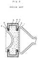
- FIG. 3 is a sectional view showing an example of the optical coupling in the conventional projection television receiver.
- a cathode-ray tube 1 is sealed and fixed to a radiator 4 through a first O-ring 5.
- a projection lens 2 is sealed and fixed to the radiator 4 through a second O-ring 6.
- the region enclosed by the cathode-ray tube 1, projection lens 2 and radiator 4 is filled with a refrigerant liquid 3.
- the radiator 4 is made of aluminum die-cast, and an alumite film 7 is formed on the surface.
- the alumite film is an aluminum oxide film formed by anodic oxidation of aluminum die-cast.
- the conventional forming process of alumite film required acid treatment as pretreatment for removing impurities on the die-cast surface.
- This acid treatment caused to roughen the surface of the radiator 4. If control of this treatment process is insufficient, the surface roughness of the radiator 4 fluctuates largely, possibly leading to seal failure. This seal failure involves a problem in quality control because it may lead to a liquid leak accident.
- the surface of the radiator 4 is dyed in black. This black dyestuff is sometimes peeled off from the surface of the radiator 4 to drop into the refrigerant liquid. To prevent such peeling, it requires a step of cleaning the radiator 4 before assembling, and the step of cleaning the radiator 4 has caused to increase the number of manufacturing steps.
- the projection television receiver of the invention comprises a cathode-ray tube having a face surface, a projection lens disposed ahead of the face surface, a container disposed between the face surface and projection lens, and liquid filling up the container, in which the container has a fluoride resin film disposed at least inside of the container, and the fluoride resin film contacts with the liquid.
- the projection television receiver further comprises a first sealing member disposed between the container and face surface, and a second sealing member disposed between the container and projection lens, in which the first sealing member is disposed in a state tightly contacting with the face surface and fluorine resin film to prevent the liquid from leaking out from between the container and face surface, and the second sealing member is disposed in a state tightly contacting with the projection lens and fluorine resin film to prevent the liquid from leaking out from between the container and projection lens.
- the fluoride resin film has a stable corrosion resistance to the liquid.
- a projection television receiver comprises a cathode-ray tube having a face surface, a projection lens disposed ahead of the face surface, a container disposed between the face surface and projection lens, a first sealing member disposed between the container and face surface, a second sealing member disposed between the container and projection lens, and liquid filling up the space enclosed by the face surface, projection lens and container, and the surface of the container is coated with a fluoride resin.
- the smoothness of the container surface is improved. Further, the corrosion resistance of the container is improved. As a result, liquid leak is prevented. Also peeling of film is prevented, and a projection television receiver of high reliability is obtained.
- the assembling processes are curtailed, and the manufacturing cost is reduced.
- the fluoride resin film is applied in part or whole of the container surface.
- liquid leak is prevented.
- the reliability is enhanced. Further, the assembling processes are curtailed.
- the container is fabricated by aluminum die-casting.
- liquid leak is prevented.
- the reliability is enhanced. Further, the assembling processes are curtailed.
- the fluoride resin is made of polytetrafluoroethylene (PTFE).
- PTFE polytetrafluoroethylene
- the fluoride resin film is formed to make smooth the fine undulated surface of the container.
- the fluoride resin film is formed so as to fill up the recesses of the fine undulated surface of the aluminum die-cast.
- a cathode-ray tube 1 is sealed and fixed in a container 4 through a first sealing member 5.
- a projection lens 2 is sealed and fixed in the container 4 through a second sealing member 6.
- a fluoride resin film 8 is disposed on the surface of the container 4.
- the region enclosed by the cathode-ray tube 1, projection lens 2 and container 4 is filled up with a refrigerant liquid 3.
- the cathode-ray tube 1, first sealing member 5, container 4, second sealing member 6, and projection lens 2 are mutually pressurized.
- annular O-rings are used as the first sealing member 5 and second sealing member 6, annular O-rings are used.
- the annular O-rings have an elasticity for compressing and deforming against pressurization.
- the container 4 and refrigerant liquid 3 compose an optical coupling.
- an image light is formed on the face surface of the cathode-ray tube 1.
- This image light passes through the refrigerant liquid 3 and gets into the projection lens 2.
- the image light is magnified by the projection lens 2, and is displayed on a screen (not shown).
- the container 4 is manufactured by casting and forming aluminum. That is, the container 4 is manufactured by aluminum die-casting.
- the container 4 is a radiator.
- a fluoride resin film 8 is placed at least on the inner surface of the container 4.
- the container functions as radiator.
- the container 4 is formed by aluminum die-casting.
- the fluoride resin film 8 is disposed on the inner surface contacting with the refrigerant liquid 3.
- the fluoride resin film 8 is formed by dip coating method of immersing the aluminum die-cast in the paint, or spray coating method of spraying the paint on the surface of the aluminum die-cast.
- the manufacturing method of the container 4 comprises a step of forming a die-cast molding of a specified shape by casting and forming aluminum, and a step of disposing the fluoride resin film 8 on the surface of the die-cast molding.
- the step of disposing the fluoride resin film 8 includes a step of heating the die-cast molding, and a step of forming the fluoride resin film on the entire surface of the inner surface and outer surface of the die-cast molding by dipping (immersing) the heated die-cast molding in powder paint of fluoride resin. In this process, the powder of the fluoride resin contacting with the heated die-cast molding is fused, and simultaneously the fluoride resin film is adhered and formed.
- the step of disposing the fluoride resin film 8 includes a step of applying a paint containing fluoride resin on a specified surface of the die-cast molding by spraying or dipping method, and melting and drying the adhered paint.
- fluoride resin examples include polytetrafluoroethylene, polychlorotrifluoroethylene, polytetrafluoroethylene-hexafluoropropylene, polyvinylidene fluoride, copolymer of chlorotrifluoroethylene and vinylidene fluoride, and copolymer of vinylidene fluoride and hexafluoropropylene.
- fluoride resin include polytetrafluoroethylene, polychlorotrifluoroethylene, polytetrafluoroethylene-hexafluoropropylene, polyvinylidene fluoride, copolymer of chlorotrifluoroethylene and vinylidene fluoride, and copolymer of vinylidene fluoride and hexafluoropropylene.
- polytetrafluoroethylene is preferable.
- the thickness of the fluoride resin film 8 is preferred to be in a range of about 0.5 ⁇ m to about 200 ⁇ m. More preferably, the fluoride resin film 8 has a thickness in a range of about 5 ⁇ m to about 50 ⁇ m. If the thickness of the fluoride resin film 8 is less than about 0.5 ⁇ m, the smoothness of the fluoride resin film 8 is slightly inferior. If the thickness of the fluoride resin film 8 exceeds about 200 ⁇ m, the film thickness tends to be slightly unstable, and the material cost and manufacturing cost are higher.
- the container has a first groove formed at the cathode-ray tube side, and a second groove formed at the projection lens side.
- the first sealing member 5 is positioned in the first groove.
- the second sealing member 6 is positioned in the second groove.
- the first sealing member and second sealing member are disposed in contact with the groove bottom in pressurized state.
- the sealing effect is further increased.
- the fluoride resin film is disposed on the surface in the groove, and the sealing members are disposed in contact with the fluoride resin film in the grooves in pressurized state. In this constitution, the sealing effect is notably increased.
- the fluoride resin film has a property to be compressed and deformed by pressurizing, and the sealing members and fluoride resin film are mutually pressurized, and contacting tightly as being compressed and deformed. In this constitution, the sealing effect is further increased.
- the fluoride resin that is compressed and deformed by pressurization includes polytetrafluoroethylene, polyvinylidene fluoride, copolymer of chlorotrifluoroethylene and vinylidene fluoride, and copolymer of vinylidene fluoride and hexafluoropropylene.
- a clear liquid or a transparent liquid is used.
- an organic solvent is used as the refrigerant liquid 3.
- the organic solvent includes, for example, a glycol compound.
- the face surface of the cathode-ray tube 1 and the projection lens 2 have a surface roughness of smaller than about 1.5 ⁇ m.
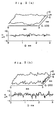
- the surface roughness of the container having the fluoride resin film used in the embodiment manufactured by aluminum die-casting was measured by a three-dimensional surface roughness gauge. Results of measurement of surface roughness are shown in Fig. 2 (a).
- the surface roughness "Ra" of the container having the fluoride resin film 8 was about 0.6 ⁇ m. Fluctuations of surface roughness were small.
- the surface roughness of the container 4 is preferred to be less than about 1.5 ⁇ m, and more preferably 1.0 ⁇ m or less. If the surface roughness of the container 4 exceeds about 1.5 ⁇ m, the probability of occurrence of liquid leak is high.
- the container having the fluoride resin film 8 of the embodiment has a surface roughness of about 1/3 as compared with the conventional container having alumite film, and has a surface of an excellent smoothness. Therefore, the sealing tightness between the container 4 and first sealing member 5 is improved, and liquid leak is prevented. Thus, the reliability of the television receiver is notably enhanced.
- the cathode-ray tube 1 During use of the projection television receiver, the cathode-ray tube 1 generates heat. Therefore, the refrigerant liquid 3 contained in the container 8 is heated to about 80°C. That is, the surface of the container 4 contacts with the refrigerant liquid 3 at about 80°C for a long time.
- the aluminum die-cast having polytetrafluoroethylene was immersed in the refrigerant liquid at 80°C for 1000 hours, and the surface state of the container was observed, and also elution of impurities in the refrigerant liquid was checked. Glycol compound was used as the refrigerant liquid. As a result, the polytetrafluoroethylene film was free from peeling, dissolving, swelling, crack or other abnormality.
- Such fluoride resin film is a kind of super-engineering plastics, and in particular such fluoride resin film has an excellent corrosion resistance to refrigerant liquid, and a superior resistance to heat.
- the container forming the fluoride resin film 8 has a stable heat resistance, solvent resistance, and corrosion resistance. Not required to clean before assembling, the cleaning step can be omitted. The excellent quality lasts long in the solvent at high temperature. Further, the fluoride resin film 8 disposed on the surface of the container contacts tightly with the sealing members 5, 6 in pressurized state, so that leak of refrigerant liquid 3 is prevented securely.
- fluoride resin film in particular polytetrafluoroethylene film is most preferred, and very excellent effects are obtained.
- the fluoride resin film 8 has, preferably, a property to be compressed and deformed by pressurizing. In pressurized state, when the sealing members 5, 6 contact tightly with the fluoride resin film 8, fine bumps of the fluoride resin film 8 are compressed, and fine gaps between the sealing members 5, 6 and the fluoride resin film 8 are further made smaller. Therefore, the effect of preventing liquid leak is further enhanced.
- the film of polytetrafluoroethylene has a property to be compressed and deformed by pressurizing.
- leak of refrigerant liquid is prevented according to the invention. Further, invasion of impurities into the refrigerant liquid is prevented, and a stable projection image is obtained. The assembling steps are curtailed, and the projection television receiver is manufactured by a smaller number of assembling steps, and the cost is reduced. Moreover, a stable quality is maintained for a long period, and a high reliability is obtained.
Landscapes
- Engineering & Computer Science (AREA)
- Multimedia (AREA)
- Signal Processing (AREA)
- Cathode-Ray Tubes And Fluorescent Screens For Display (AREA)
- Transforming Electric Information Into Light Information (AREA)
- Vessels, Lead-In Wires, Accessory Apparatuses For Cathode-Ray Tubes (AREA)
Applications Claiming Priority (2)
| Application Number | Priority Date | Filing Date | Title |
|---|---|---|---|
| JP17937599 | 1999-06-25 | ||
| JP17937599A JP3700479B2 (ja) | 1999-06-25 | 1999-06-25 | 投写形受像機 |
Publications (3)
| Publication Number | Publication Date |
|---|---|
| EP1063675A2 true EP1063675A2 (fr) | 2000-12-27 |
| EP1063675A3 EP1063675A3 (fr) | 2003-10-29 |
| EP1063675B1 EP1063675B1 (fr) | 2007-01-17 |
Family
ID=16064767
Family Applications (1)
| Application Number | Title | Priority Date | Filing Date |
|---|---|---|---|
| EP00113400A Expired - Lifetime EP1063675B1 (fr) | 1999-06-25 | 2000-06-23 | Récepteur de télévision par projection |
Country Status (8)
| Country | Link |
|---|---|
| US (1) | US6525784B1 (fr) |
| EP (1) | EP1063675B1 (fr) |
| JP (1) | JP3700479B2 (fr) |
| KR (1) | KR100560238B1 (fr) |
| CN (1) | CN1311682C (fr) |
| DE (1) | DE60032970T2 (fr) |
| MX (1) | MXPA00006165A (fr) |
| MY (1) | MY124712A (fr) |
Families Citing this family (3)
| Publication number | Priority date | Publication date | Assignee | Title |
|---|---|---|---|---|
| CN1312917C (zh) * | 2002-09-09 | 2007-04-25 | 四川长虹电器股份有限公司 | 投影电视冷媒自动灌装机 |
| KR100672507B1 (ko) | 2004-05-20 | 2007-01-24 | 엘지전자 주식회사 | Crt프로젝션 tv의 커플러구조 |
| JP5493609B2 (ja) * | 2008-09-18 | 2014-05-14 | ソニー株式会社 | 液体レンズ、及び撮像装置 |
Family Cites Families (13)
| Publication number | Priority date | Publication date | Assignee | Title |
|---|---|---|---|---|
| JPS6235429A (ja) * | 1985-08-06 | 1987-02-16 | Pioneer Electronic Corp | プロジエクシヨンテレビ用冷却装置 |
| JPS6243278A (ja) | 1985-08-21 | 1987-02-25 | Hitachi Ltd | 投写装置 |
| US4710820A (en) * | 1986-05-22 | 1987-12-01 | Zenith Electronics Corporation | Single layer optical coupler for projection TV CRT |
| US4982289A (en) * | 1989-05-15 | 1991-01-01 | Matsushita Electric Industrial Co., Ltd. | Liquid cooled cathode ray tube apparatus for video projection system |
| US5117162A (en) * | 1990-12-20 | 1992-05-26 | North American Philips Corporation | Optical grade transfer coolant for projection television receivers |
| JPH04314044A (ja) | 1991-04-12 | 1992-11-05 | Toshiba Corp | 投写形テレビジョン受像装置 |
| FR2680583B1 (fr) * | 1991-08-22 | 1993-10-08 | Commissariat A Energie Atomique | Materiau presentant des proprietes antireflet, hydrophobes et de resistance a l'abrasion et procede de depot d'une couche antireflet, hydrophobe et resistante a l'abrasion sur un substrat. |
| JPH05341167A (ja) * | 1992-06-08 | 1993-12-24 | Matsushita Electric Ind Co Ltd | レンズ保持部材と薄膜形成方法 |
| JPH06265782A (ja) * | 1993-03-16 | 1994-09-22 | Matsushita Electric Ind Co Ltd | 投写レンズ装置 |
| CN1078802A (zh) * | 1993-03-19 | 1993-11-24 | 张留刚 | 聚四氟乙烯金属复合换热器 |
| CN1052795C (zh) * | 1993-12-21 | 2000-05-24 | 美国3M公司 | 光学显示器 |
| US5981059A (en) * | 1995-04-03 | 1999-11-09 | Southwall Technologies, Inc. | Multi-layer topcoat for an optical member |
| US5892627A (en) * | 1997-04-29 | 1999-04-06 | Thomson Consumer Electronics, Inc. | Elastomer lined CRT-to-lens coupler |
-
1999
- 1999-06-25 JP JP17937599A patent/JP3700479B2/ja not_active Expired - Fee Related
-
2000
- 2000-05-31 MY MYPI20002432A patent/MY124712A/en unknown
- 2000-06-19 US US09/596,588 patent/US6525784B1/en not_active Expired - Fee Related
- 2000-06-21 MX MXPA00006165A patent/MXPA00006165A/es active IP Right Grant
- 2000-06-23 DE DE60032970T patent/DE60032970T2/de not_active Expired - Fee Related
- 2000-06-23 CN CNB001187481A patent/CN1311682C/zh not_active Expired - Fee Related
- 2000-06-23 EP EP00113400A patent/EP1063675B1/fr not_active Expired - Lifetime
- 2000-06-24 KR KR1020000035017A patent/KR100560238B1/ko not_active Expired - Fee Related
Also Published As
| Publication number | Publication date |
|---|---|
| CN1311682C (zh) | 2007-04-18 |
| MY124712A (en) | 2006-06-30 |
| CN1287446A (zh) | 2001-03-14 |
| US6525784B1 (en) | 2003-02-25 |
| EP1063675B1 (fr) | 2007-01-17 |
| EP1063675A3 (fr) | 2003-10-29 |
| JP3700479B2 (ja) | 2005-09-28 |
| MXPA00006165A (es) | 2002-03-08 |
| KR20010007516A (ko) | 2001-01-26 |
| KR100560238B1 (ko) | 2006-03-10 |
| DE60032970D1 (de) | 2007-03-08 |
| DE60032970T2 (de) | 2007-05-24 |
| JP2001008134A (ja) | 2001-01-12 |
Similar Documents
| Publication | Publication Date | Title |
|---|---|---|
| JP7529422B2 (ja) | レンズユニット | |
| US9995991B2 (en) | Image pickup apparatus | |
| JP5070517B2 (ja) | 気密エレクトロウェッティング装置 | |
| US5541776A (en) | Fluid type optical device | |
| US6525784B1 (en) | Projection television receiver | |
| US20080316587A1 (en) | Solution Flow Prevention in Fluid Focus Lenses | |
| WO2016038874A1 (fr) | Unité de filtre | |
| US4425416A (en) | Color filter and method for manufacturing the same | |
| JP6174904B2 (ja) | レンズユニットおよび光学ユニット | |
| WO2023221637A1 (fr) | Lentille d'imagerie | |
| JP6439366B2 (ja) | 光学部材の製造方法 | |
| WO1998049831A1 (fr) | Coupleur tube cathodique-lentille recouvert d'elastomere | |
| JP2025077549A (ja) | レンズユニット及びカメラモジュール | |
| KR102536814B1 (ko) | 고압 수소저장용기용 보스 및 그 제조방법 | |
| WO2019228110A1 (fr) | Lentille de caméra optique, module photographique, et leur procédé d'assemblage | |
| KR0133895Y1 (ko) | 프로젝션 텔레비젼의 음극선관 냉각장치 | |
| MXPA99009942A (es) | Acoplador de tubo de rayos catodicos cubierto con elastomero a lente | |
| JPH0367264A (ja) | 感光体塗布装置 | |
| JPH06297479A (ja) | プラスチックレンズの注型成形用モールドおよびそれを用いたプラスチックレンズの注型成形方法 | |
| JPH0659187A (ja) | 投写レンズ装置 |
Legal Events
| Date | Code | Title | Description |
|---|---|---|---|
| PUAI | Public reference made under article 153(3) epc to a published international application that has entered the european phase |
Free format text: ORIGINAL CODE: 0009012 |
|
| AK | Designated contracting states |
Kind code of ref document: A2 Designated state(s): AT BE CH CY DE DK ES FI FR GB GR IE IT LI LU MC NL PT SE |
|
| AX | Request for extension of the european patent |
Free format text: AL;LT;LV;MK;RO;SI |
|
| RIN1 | Information on inventor provided before grant (corrected) |
Inventor name: OYA, TOMOYUKI |
|
| PUAL | Search report despatched |
Free format text: ORIGINAL CODE: 0009013 |
|
| AK | Designated contracting states |
Kind code of ref document: A3 Designated state(s): AT BE CH CY DE DK ES FI FR GB GR IE IT LI LU MC NL PT SE |
|
| AX | Request for extension of the european patent |
Extension state: AL LT LV MK RO SI |
|
| 17P | Request for examination filed |
Effective date: 20031110 |
|
| AKX | Designation fees paid |
Designated state(s): DE FR GB |
|
| GRAP | Despatch of communication of intention to grant a patent |
Free format text: ORIGINAL CODE: EPIDOSNIGR1 |
|
| GRAS | Grant fee paid |
Free format text: ORIGINAL CODE: EPIDOSNIGR3 |
|
| GRAA | (expected) grant |
Free format text: ORIGINAL CODE: 0009210 |
|
| AK | Designated contracting states |
Kind code of ref document: B1 Designated state(s): DE FR GB |
|
| REG | Reference to a national code |
Ref country code: GB Ref legal event code: FG4D |
|
| REF | Corresponds to: |
Ref document number: 60032970 Country of ref document: DE Date of ref document: 20070308 Kind code of ref document: P |
|
| ET | Fr: translation filed | ||
| RIN2 | Information on inventor provided after grant (corrected) |
Inventor name: OYA, TOMOYUKI |
|
| PLBE | No opposition filed within time limit |
Free format text: ORIGINAL CODE: 0009261 |
|
| STAA | Information on the status of an ep patent application or granted ep patent |
Free format text: STATUS: NO OPPOSITION FILED WITHIN TIME LIMIT |
|
| 26N | No opposition filed |
Effective date: 20071018 |
|
| PGFP | Annual fee paid to national office [announced via postgrant information from national office to epo] |
Ref country code: GB Payment date: 20090617 Year of fee payment: 10 Ref country code: DE Payment date: 20090619 Year of fee payment: 10 |
|
| GBPC | Gb: european patent ceased through non-payment of renewal fee |
Effective date: 20100623 |
|
| REG | Reference to a national code |
Ref country code: FR Ref legal event code: ST Effective date: 20110228 |
|
| PG25 | Lapsed in a contracting state [announced via postgrant information from national office to epo] |
Ref country code: DE Free format text: LAPSE BECAUSE OF NON-PAYMENT OF DUE FEES Effective date: 20110101 |
|
| PG25 | Lapsed in a contracting state [announced via postgrant information from national office to epo] |
Ref country code: FR Free format text: LAPSE BECAUSE OF NON-PAYMENT OF DUE FEES Effective date: 20100630 |
|
| PG25 | Lapsed in a contracting state [announced via postgrant information from national office to epo] |
Ref country code: GB Free format text: LAPSE BECAUSE OF NON-PAYMENT OF DUE FEES Effective date: 20100623 |
|
| PGFP | Annual fee paid to national office [announced via postgrant information from national office to epo] |
Ref country code: FR Payment date: 20090611 Year of fee payment: 10 |