EP1067536A2 - Belichtungsanlage und Verfahren, Laufwerk für optische Platten, und Aufzeichnungs- und/oder Wiedergabeverfahren - Google Patents
Belichtungsanlage und Verfahren, Laufwerk für optische Platten, und Aufzeichnungs- und/oder Wiedergabeverfahren Download PDFInfo
- Publication number
- EP1067536A2 EP1067536A2 EP00114303A EP00114303A EP1067536A2 EP 1067536 A2 EP1067536 A2 EP 1067536A2 EP 00114303 A EP00114303 A EP 00114303A EP 00114303 A EP00114303 A EP 00114303A EP 1067536 A2 EP1067536 A2 EP 1067536A2
- Authority
- EP
- European Patent Office
- Prior art keywords
- laser light
- gap length
- exposure
- light
- length controlling
- Prior art date
- Legal status (The legal status is an assumption and is not a legal conclusion. Google has not performed a legal analysis and makes no representation as to the accuracy of the status listed.)
- Ceased
Links
Images


Classifications
-
- G—PHYSICS
- G11—INFORMATION STORAGE
- G11B—INFORMATION STORAGE BASED ON RELATIVE MOVEMENT BETWEEN RECORD CARRIER AND TRANSDUCER
- G11B7/00—Recording or reproducing by optical means, e.g. recording using a thermal beam of optical radiation by modifying optical properties or the physical structure, reproducing using an optical beam at lower power by sensing optical properties; Record carriers therefor
- G11B7/24—Record carriers characterised by shape, structure or physical properties, or by the selection of the material
- G11B7/26—Apparatus or processes specially adapted for the manufacture of record carriers
- G11B7/261—Preparing a master, e.g. exposing photoresist, electroforming
-
- B—PERFORMING OPERATIONS; TRANSPORTING
- B82—NANOTECHNOLOGY
- B82Y—SPECIFIC USES OR APPLICATIONS OF NANOSTRUCTURES; MEASUREMENT OR ANALYSIS OF NANOSTRUCTURES; MANUFACTURE OR TREATMENT OF NANOSTRUCTURES
- B82Y10/00—Nanotechnology for information processing, storage or transmission, e.g. quantum computing or single electron logic
-
- G—PHYSICS
- G03—PHOTOGRAPHY; CINEMATOGRAPHY; ANALOGOUS TECHNIQUES USING WAVES OTHER THAN OPTICAL WAVES; ELECTROGRAPHY; HOLOGRAPHY
- G03F—PHOTOMECHANICAL PRODUCTION OF TEXTURED OR PATTERNED SURFACES, e.g. FOR PRINTING, FOR PROCESSING OF SEMICONDUCTOR DEVICES; MATERIALS THEREFOR; ORIGINALS THEREFOR; APPARATUS SPECIALLY ADAPTED THEREFOR
- G03F7/00—Photomechanical, e.g. photolithographic, production of textured or patterned surfaces, e.g. printing surfaces; Materials therefor, e.g. comprising photoresists; Apparatus specially adapted therefor
- G03F7/70—Microphotolithographic exposure; Apparatus therefor
- G03F7/70216—Mask projection systems
- G03F7/70325—Resolution enhancement techniques not otherwise provided for, e.g. darkfield imaging, interfering beams, spatial frequency multiplication, nearfield lenses or solid immersion lenses
-
- G—PHYSICS
- G11—INFORMATION STORAGE
- G11B—INFORMATION STORAGE BASED ON RELATIVE MOVEMENT BETWEEN RECORD CARRIER AND TRANSDUCER
- G11B7/00—Recording or reproducing by optical means, e.g. recording using a thermal beam of optical radiation by modifying optical properties or the physical structure, reproducing using an optical beam at lower power by sensing optical properties; Record carriers therefor
- G11B7/08—Disposition or mounting of heads or light sources relatively to record carriers
- G11B7/09—Disposition or mounting of heads or light sources relatively to record carriers with provision for moving the light beam or focus plane for the purpose of maintaining alignment of the light beam relative to the record carrier during transducing operation, e.g. to compensate for surface irregularities of the latter or for track following
- G11B7/0908—Disposition or mounting of heads or light sources relatively to record carriers with provision for moving the light beam or focus plane for the purpose of maintaining alignment of the light beam relative to the record carrier during transducing operation, e.g. to compensate for surface irregularities of the latter or for track following for focusing only
-
- G—PHYSICS
- G11—INFORMATION STORAGE
- G11B—INFORMATION STORAGE BASED ON RELATIVE MOVEMENT BETWEEN RECORD CARRIER AND TRANSDUCER
- G11B7/00—Recording or reproducing by optical means, e.g. recording using a thermal beam of optical radiation by modifying optical properties or the physical structure, reproducing using an optical beam at lower power by sensing optical properties; Record carriers therefor
- G11B7/12—Heads, e.g. forming of the optical beam spot or modulation of the optical beam
- G11B7/122—Flying-type heads, e.g. analogous to Winchester type in magnetic recording
-
- G—PHYSICS
- G11—INFORMATION STORAGE
- G11B—INFORMATION STORAGE BASED ON RELATIVE MOVEMENT BETWEEN RECORD CARRIER AND TRANSDUCER
- G11B7/00—Recording or reproducing by optical means, e.g. recording using a thermal beam of optical radiation by modifying optical properties or the physical structure, reproducing using an optical beam at lower power by sensing optical properties; Record carriers therefor
- G11B7/12—Heads, e.g. forming of the optical beam spot or modulation of the optical beam
- G11B7/135—Means for guiding the beam from the source to the record carrier or from the record carrier to the detector
- G11B7/1387—Means for guiding the beam from the source to the record carrier or from the record carrier to the detector using the near-field effect
Definitions
- the present invention relates to an exposure apparatus and method, an optical disc drive for, and recording and/or reproducing method of, recording and/or reproducing information signal to and/or from a signal recording medium.
- Write or read of information signal to or from an optical disc is done by condensing a laser light to a predetermined spot diameter and projecting it to a signal recording layer of an optical recording medium.
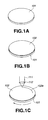
- a disc-like substrate 101 having a smooth, mirror-finished surface is prepared as shown in FIG. 1A.
- the substrate 101 is made of glass, for example.
- the substrate 101 is applied to the smooth, mirror-finished surface thereof with a photoresist layer 102 to a predetermined thickness.
- a laser light is projected through an objective lens 112 to the photoresist layer 102 on the substrate 101 being rotated as shown in FIG. 1C.
- the objective lens 112 is moved in the direction of the optical axis thereof so that a laser light spot having a predetennined diameter will be defined on the photoresist layer 102. Namely, the laser light is focused on the photoresist layer 102.
- the photoresist layer 102 will have a pattern of latent pit or groove images formed therein.
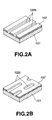
- parts of the photoresist layer 102 on the substrate 101 are removed according to the exposed pattern as shown in FIG. 2, to provide an original substrate having tiny pits or grooves formed and which is used for further preparing a stamper for manufacture of an optical disc.
- the tiny concavities and convexities 102b in the photoresist layer 102 as shown in FIG. 2A will result in lands and grooves in the optical disc, while the tiny concavities and convexities 102c in the photoresist layer 102 as shown in FIG. 2B will result in pits in the optical disc.
- the original substrate thus formed using the exposure apparatus is used to prepare a stamper for use to manufacture an optical disc.
- a technique is required to irradiate a light sport having a predetermined diameter to an object such as an original substrate for manufacture of an optical disc and the optical disc itself.
- the astigmatic method, skew beam method, knife edge method, etc. are adopted to control the distance between the objective lens and object (will be referred to as "gap length" hereinafter).
- all these methods use a reflected laser light from the signal recording layer of the optical disc.
- SIL solid immersion lens
- the condenser lens and SIL form together a so-called two-group lens.
- a larger numerical aperture than that of the condenser lens (larger than 1 for example) can be realized.
- the SIL is disposed on the optical disc so that the distance (namely, gap length) between the main side thereof (opposing the optical disc) and optical disc is on the order of 100 nm and thus within a so-called near-field area.
- the gap length between the SIL and an object is outside the near-field area when the numerical aperture is larger than 1, a component of the intensity of the laser light outgoing from the SIL towards the optical disc, which causes the numeral aperture to be larger than 1, is considerably low. Therefore, it is necessary to control the gap length for the gap length to be constant inside the near-field area.
- the gap length between the SIL and object varies in a very narrow range such as the near-field area
- the reflected laser light from the optical disc will vary very little. So, it is difficult to detect the gap length between the SIL and object with a high accuracy based on a variation of the reflected laser light from the optical disc. Therefore, with the conventional control of the gap length based on the reflected laser light from the optical disc, it is difficult to control the gap length between the SIL and object with a high accuracy.
- the present invention has an object to overcome the above-mentioned drawbacks of the prior art by providing an exposure apparatus and method, and recording and/or reproducing apparatus and method, in which the gap length in the near-field area can be controlled with a high accuracy.
- the above object can be attained by providing an exposure apparatus having a convergent lens disposed opposite to an object and in a near-field of the object to converge an exposure laser light on the object, the apparatus including according to the present invention:
- the gap length controlling laser light different in wavelength from the exposure laser light is projected onto the convergent lens by the light projecting means, and the intensity of the return part of the gap length controlling laser light from the surface of the convergent lens opposite to the object is detected by the light intensity detecting means. Based on the return light intensity detected by the light intensity detecting means, the gap length between the convergent lens and object is controlled by the gap length controlling means.
- the gap length between the convergent lens which condenses the exposure laser light on the object and the object is controlled based on the detected intensity of the return part of the gap length controlling laser light from the surface of the convergent lens opposite to the object.
- the above object can be attained by providing an exposure method in which in which an exposure laser light is converged on an object by a convergent lens disposed opposite to the object and in a near-field area of the object, the method including, according to the present invention, steps of:
- the gap length between the convergent lens which condenses the exposure laser light on the object and the object is controlled based on the detected intensity of the return part of the gap length controlling laser light from the surface of the convergent lens opposite to the object.
- an optical disc drive having a convergent lens disposed opposite to a signal recording medium object and in a near-field of the signal recording medium to converge a writing and/or reading laser light on the signal recording medium, the apparatus including according to the present invention:
- the gap length controlling laser light different in wavelength from the writing and/or reading laser light is projected onto the convergent lens by the light projecting means, and the intensity of the return part of the gap length controlling laser light from the surface of the convergent lens opposite to the signal recording medium is detected by the light intensity detecting means. Based on the return light intensity detected by the light intensity detecting means, the gap length between the convergent lens and signal recording medium is controlled by the gap length controlling means.
- the gap length between the convergent lens which condenses the exposure laser light on the object and the object is controlled based on the detected intensity of the return part of the gap length controlling laser light from the surface of the convergent lens opposite to the object.
- the above object can be attained by providing a recording and/or reproducing method in which in which a writing and/or reading laser light is converged on a signal recording medium by a convergent lens disposed opposite to the signal recording medium and in a near-field area of the signal recording medium, the method including, according to the present invention, steps of:
- the gap length between the convergent lens which condenses the exposure laser light on the object and the object is controlled based on the detected intensity of the return part of the gap length controlling laser light from the surface of the convergent lens opposite to the object.
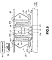
- the exposure apparatus has an optical head generally indicated with a reference 10.
- the optical head 10 includes an exposure light source 11, dichroic mirror 12, moving member 13, condenser lens 14, solid immersion lens (SIL) 15, gap length controlling light source 16, beam expander 17 consisting of a condenser lens 17a and collimator lens 17b, polarizing beam splitter 19, 1/4 wave plate 20, condenser lens 21, and a photodetector 22.
- SIL solid immersion lens
- the condenser lens 14 and SIL 15 form together a so-called two-group objective lens.
- the exposure light source 11 is provided to emit an exposure laser light.
- the gap length controlling light source 16 is provided to emit a gap length controlling laser light different in wavelength from the exposure laser light.
- the condenser lens 17a, collimator lens 17b and dichroic mirror 12 are provided to project the gap length controlling laser light onto the converging lens consisting of the condenser lens 14 and SIL 15.
- the photodetector 22 is provided to detect the intensity of a return part of the gap length controlling laser light from a surface of the SIL 15 opposite to an object 100.
- the condenser lens 14 and SIL 15 work together to converge the laser light.
- the exposure apparatus further includes a controlling means (not shown) for controlling the gap (or gap length) between the SIL 15 and object 100 based on the intensity of return light, detected by the photodetector 22.
- the SIL 15 provided in the exposure apparatus as a lens facing the object 100 which is a photoresist-coated substrate for an optical disc stamper, permits to project a light spot in a so-called near-field area.
- the object 100 is a substrate 101 having a photoresist 102 layer applied thereon.
- the substrate 101 is made of glass for example.
- the exposure light source 11 emits an exposure laser light to which the photoresist layer 102 is sensitive. More specifically, the exposure laser light has a wavelength of 413 nm, which is shorter than that the gap length controlling laser light which will further be described.
- the exposure laser light emitted from the exposure light source 11 is passed through the dichroic mirror 12 and incident upon the condenser lens 14.
- the dichroic mirror 12 is provided to reflect the gap length controlling laser light as will further be described later.
- the exposure laser light incident upon the condenser lens 14 is converged by the lens 14 itself and incident upon the SIL 15.
- the SIL 15 forms along with the condenser lens 14 the converging lens which condenses the exposure laser light onto the object 100.
- the condenser lens 14 is generally called "objective lens” in the technology in which it is used along with such a solid immersion lens to implement a high density recording optical disc.
- the SIL 15 is generally hemispheric. It consists of an incident surface 15a upon which the laser light having passed through the condenser lens 14 is incident, and a generally flat surface 15b opposing the object 100 (will be referred to as "outgoing surface” hereinafter).
- the laser light passed through the condenser lens 14 is refracted at the incident surface 15a of the SIL 15 having the above-mentioned structure, and further at the outgoing surface 15b.
- a light spot is defined on the object 100.
- NA n ⁇ sin ⁇ max
- n a refractive index of the SIL 15
- ⁇ max the maximum incident angle.
- the refractive index n and maximum incident angle 6 max are set based on a relation that the product (n ⁇ sin ⁇ 0 ) of a constant incident angle ⁇ 0 smaller than the maximum incident angle ⁇ max and the refractive index n is 1.
- the SIL 15 and condenser lens 14 are supported together by a support member 23 having a moving member 13 fixed at the end thereof.
- the moving member 13 moves the support member 23 and thus moves the condenser lens 14 and SIL 15 fixed to the support member 23 and forming together the two-group lens towards and away from the object 100.
- the moving member 13 is a piezo stack which can be extended and shrunk when supplied with a voltage.
- the gap length between the outgoing surface 15b of the SIL 15 and the object 100 is adjusted to a predetermined distance by controlling the extension and shrinkage of the moving member 13.
- the exposure laser light going out of the SIL 15 will define a desired light spot on the object 100.
- This gap length is controlled based on the gap length control laser light emitted from the gap length controlling light source 16.
- the gap length controlling light source 16 emits a laser light different in wavelength from the exposure light source 11.
- the wavelength of the gap length controlling laser light is longer than that of the exposure laser light and not in a range to which the object 100 is sensitive.
- the gap length controlling light source 16 is a helium (He)-neon (Ne) gas laser light source which emits a gap length controlling laser light whose wavelength is 633 nm.
- the gap length controlling laser light emitted from the gap length controlling light source 16 will have the laser light diameter changed by the beam 17 to a larger one than that of the laser light emitted from the gap length controlling light source 16.
- the gap length controlling laser light having the increased diameter is passed through the polarizing beam splitter 19 and 1/4 wave plate 20 and incident upon the dichroic mirror 12.
- the polarizing beam splitter 19 and 1/4 wave plate 20 are provided for the photodetector 22 to detect a return part of the gap length controlling laser light as will further be described later.
- the dichroic mirror 12 is provided to reflect a light of a predetermined wavelength, and set to reflect the gap length controlling laser light emitted from the gap length controlling light source 16. Also the dichroic mirror 12 is disposed in the light path of the exposure laser light emitted from the exposure light source 11, and the exposure laser light is passed through the dichroic mirror 12 and incident upon the condenser lens 14 as in the above. The gap length controlling laser light is reflected by the dichroic mirror 12 towards the condenser lens 14.
- the gap length controlling laser light incident upon the condenser lens 14 is projected to the object 100 through the condenser lens 14 and SIL 15. Namely, the gap length controller laser light is projected to the object 100 along a similar optical path to that of the exposure laser light. That is, the gap length controlling laser light reflected by the dichroic mirror 12 and the exposure laser light will be combined on the same optical path and incident upon the condenser lens 14 and SIL 15.
- gap length controlling return light a part reflected at the outgoing surface 15b of the SIL 15 (will be referred to as "gap length controlling return light" hereinafter) is incident upon the dichroic mirror 12 through the SIL 15 and condenser lens 14.
- the gap length controlling return light has such a wavelength that the return light will not be passed through the dichroic mirror 12, and so it will be reflected by the dichroic mirror 12 towards the 1/4 wave plate 20 where a circularly polarized light is converted to a linearly polarized one.
- exposure return light a part reflected at the outgoing surface 15b of the SIL 15 (will be referred to as "exposure return light” hereinafter) is incident upon the dichroic mirror 12 through the SIL 15 and condenser lens 14.
- the waveband of the dichroic mirror 12 in which the laser light is allowed to pass is set based on the wavelength of the exposure laser light, the exposure return light will be passed towards the exposure light source 11 without being reflected by the dichroic mirror 12.
- the gap length controlling return light converted to a linearly polarized light by the 1/4 wave plate 20 is reflected at a reflecting surface 19a of the polarizing beam splitter 19 towards the photodetector 22.
- the gap length controlling return light reflected towards the photodetector 22 is converged by the condenser lens 21 and detected by the photodetector 22 which will provide an electric signal corresponding to the intensity of the light detected by the photodetector 22.
- the electric signal output from the photodetector 22, corresponding to the detected light intensity is monitored for servo control of the gap length.
- a voltage is applied to the moving member 13 being a piezo stack, for example, to move the SIL 15 upward to near the object 100 having the photoresist layer 102 applied thereon, thereby moving the SIL 15 to a near-field area in which there is little gap between the outgoing surface 15b of the SIL 15 and the surface of the photoresist 102.
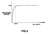
- the laser light of high frequency when the SIL 15 is moved away from the object 100 in the near-field area, the laser light of high frequency not going out of the outgoing surface 15b of the SIL 15 but reflected at the outgoing surface 15b radically increases.
- the laser light of high frequency is nearly full (100%) reflected at the outgoing surface 15b.
- the SIL 15 As the SIL 15 is moved towards the near-field area, more laser light of high frequency is passed through the outgoing surface 15b, so that the part of the laser light will decrease. For example, when the gap between the SIL 15 and object 100 is short as shown in FIG. 4, the reflectance at the outgoing surface 15b of the SIL 15 becomes low. Therefore, when the SIL 15 reaches the near-field area, the photodetector 22 will detect a reduced amount of light.
- the above phenomenon is utilized in the exposure apparatus to control the gap length.
- the intensity of the gap length controlling return light is detected by the photodetector 22, and the gap length is controlled based on the detected intensity of the return light.
- the moving member 13 is driven to move the SIL 15 to near the near-field area until the photodetector 22 detects a predetermined reduced intensity of the gap length controlling return light, thereby controlling the gap length so that the photoresist layer 102 on the object 100 can be exposed to a desired light spot.
- the gap length is controlled so that the photodetector 22 detects 60% of the intensity of the gap length controlling return light which would be when the gap length controlling laser light is totally reflected.
- the use of the exposure beam to control the gap length will be considered herebelow.
- the exposure power depending upon a linear velocity varies, and output of the exposure beam varies due to modulation. For example, when the output is turned on and off repeatedly, the gap length controlling signal and modulation signal will be superposed, resulting in a servo control system which is not stable.
- the embodiment of the exposure apparatus includes the gap length controlling light source 16 separately from the exposure light source 11.
- the gap length can be controlled without the influence of the variation of the exposure power due to a linear velocity change and the variation of the laser output due to a modulation. Therefore, since the gap length can be controlled using the gap length controlling laser light whose output is maintained constant, not any exposure laser light output or the like, the servo control can be done stably.
- the photoresist layer 102 is not susceptible to the gap length controlling laser light.
- the gap length controlling laser light has a wavelength to which the photoresist layer 102 is not sensitive, it is possible to select a gap length controlling laser light output with an increased freedom.
- the gap length controlling laser light output is increased so that a large signal-to-noise (S/N) ratio of the return light detection can be selected, for example. Thereby, the servo control can be effected more stably.
- the present invention has been described concerning the embodiment of the exposure apparatus. As having previously been mentioned, however, the present invention is applicable to an optical disc drive to and/or from which information signal can be written and/or read.
- the optical disc drive includes an optical head 10 which is constructed generally similarly to th exposure apparatus having been described in the foregoing.
- the same parts as in the exposure apparatus will be indicated with the same reference numerals as in FIG. 3 and will not be described below any longer.
- the optical head 10 includes a polarizing beam splitter 31, condenser lens 32 and a photodetector 33 to reproduce a return part of a laser light projected to an optical disc 150 and modulated by information signal on the optical disc 150 (the return part will be referred to as "information-modulated return light” hereinafter). Also the optical head 10 includes a light source 34 to emit a writing and/or reading laser light.
- optical disc drive includes an RF amplifier 41, digital signal processor 42, laser driver 43, gap length controller 44, rotation servo controller 45, spindle motor 46 and a system controller 47. These components are provided to process the information read from the optical disc 150 by the optical head 10.
- the writing and/or reading light source 34 is controlled, concerning its output, by the laser driver 43 whether write or read is made.
- the laser light emitted from the writing and/or reading light source 34 is passed through the polarizing beam splitter 31 and then through the dichroic mirror 12, condenser lens 14 and SIL 15 as in the exposure apparatus and condensed on the signal recording layer of the optical disc 150.
- the information-modulated return light from the signal recording layer is incident upon the polarizing beam splitter 31 through the SIL 15, condenser lens 14 and dichroic mirror 12.
- the information-modulated return light is reflected at a reflecting surface 31a of the polarizing beam splitter 31 towards the photodetector 33.
- a condenser lens 32 which will condense the information-modulated return light on the photodetector 33.
- the photodetector 33 provides an electric signal corresponding to the intensity of the return light.
- the electric signal output from the photodetector 33 is supplied to the RF amplifier 41 where it will be amplified.
- the read signal thus amplified in the RF amplifier 41 is supplied to the digital signal processor 42.
- the digital signal processor 42 converts the supplied read signal to a digital signal.
- the system controller 47 controls each of the components of the optical disc drive. For example, the system controller 47 controls the optical disc rotation servo system and output of the writing and/or reading light source 34 based on the digital signal output from the digital signal processor 42.
- the laser driver 43 is supplied with a control signal from the system controller 47 and controls the output of the writing and/or reading light source 34. More specifically, the laser driver 43 controls, according to the control signal from the system controller 47, the laser light output of the writing and/reading light source 34 to a predetermined output for data read or write.
- the rotation servo controller 45 controls the operation of the spindle motor 46 which drives to rotate the optical disc 150.
- the rotation servo controller 45 is supplied with a control signal from the system controller 47 and controls the operation of the spindle motor 46 to rotate the optical disc 150 at a predetermined speed.
- the photodetector 22 provides an output signal corresponding to the intensity of the gap length controlling return light. Supplied with the output signal from the photodetector 22, the gap length controller 44 controls the gap length. In the optical disc drive, the gap length is controlled as in the exposure apparatus to drive the moving member 13 so that the intensity of the gap length controlling return light is detected by the photodetector 22 to be constant.
- a laser light having an optimum power is emitted from the writing and/or reading light source 34 to write and/or read information signal to and/or from the optical disc 150, while the gap length controlling laser light is emitted from the gap length controlling light source 16 and a gap length controlling return light from the optical disc 150 is detected by the photodetector 22 to control the gap length.
- the gap length controlling light source 16 is provided separately from the writing and/or reading light source 34 as mentioned above.
- the gap length can be controlled based on the gap length controlling return light, a return part of the gap length controlling laser light emitted from the gap length controlling light source 16, without being influenced by a variation of the exposure power due to a change of linear velocity and variation of the laser output due to the modulation by information signal.
- the gap length is controlled using the gap length controlling laser light maintained constant, not the exposure laser light for write and/or read information signal.
- the servo control can be done stably.
- a gap length controlling laser light is selected whose wavelength is not in a range to which the signal recording layer of the optical disc 150 is sensitive, information signal recorded on the signal recording layer of the optical disc 150 will not adversely be influenced.
- the gap length controlling laser light output is increased so that a large signal-to-noise (S/N) ratio of the return light detection can be selected, for example. Thereby, the servo control can be effected more stably.
- S/N signal-to-noise
- a part of the gap length controlling laser light not reflected at the outgoing surface 15b of the SIL 15 and going out of the outgoing surface 15b may possibly be reflected at the signal recording layer of the optical disc 150 and detected as a return light by the photodetector 22.
- the return light will adversely be influenced by information signal recorded in the optical disc 150.
- the return light will contain a component modulated by the information signal recorded in the optical disc 150.
- the gap length can be controlled without being influenced by any component, if any contained in the return light, modulated by the information signal.
- the gap length controlling return light may possibly contain a component modulated by the information signal under the so-called Kerr effect.
- the component can be removed by filtering.
- FIG. 6 there is illustrated in the form of a front view a second moving member 50 which may be provided in the exposure apparatus or optical disc drive to move the condenser lens 14 and SIL 15 towards and away from the object 100 or optical disc 150.
- a second moving member 50 which may be provided in the exposure apparatus or optical disc drive to move the condenser lens 14 and SIL 15 towards and away from the object 100 or optical disc 150.
- the second moving member 50 is designed to provide an air layer between the object 100 and the support member 23 to which the condenser lens 14 and SIL 15 are fixed, thus floating the support member 23.
- the second moving member 50 includes an air-slider 51, elastic member 52, air supply nozzle 53, second support member 54 and an air source 55.
- the second support member 54 supports the support member 23 having fixed thereto the condenser lens 14 and SIL 15, opposite to the object 100.
- the second support member 54 is formed generally cylindrical. It houses the support member 23 and has installed at one end thereof the first moving member 13 fixed to the support member 23.
- the air slider 51 is installed at the other end of the second support member 54.
- the air slider 51 is formed flat and has a main surface 5 la thereof fixed to the second support member 54, opposite to the object 100. As shown, the air slider 51 has penetrated therein from a rear surface 51b thereof to the man surface 51a the air supply nozzle 53 which provides an air jet.
- the second moving member 50 is supported by an arm 62. More particularly, the elastic member 52 such as a leaf spring fixed at one end thereof to the arm 62 is fixed at the other end to the rear surface 51b of the air slider 51. Thus the second moving member 50 is supported elastically by the arm 62.
- the air supply nozzle 53 is connected at the other end thereof to the air source 55 and supplied with air from the latter.
- the air supply nozzle 53 is penetrated through the arm 62 and fixed at one end thereof to the air slider 51.
- the arm 62 has formed therein a nozzle insertion hole 62a through which the air supply nozzle 53 is passed.
- the nozzle insertion hole 62a has a larger diameter than the outside diameter of the air supply nozzle 53.
- the air supply nozzle 53 is held movably through the nozzle insertion hole 62a in the arm 62.
- the arm 62 has formed therein an opening 62b through which the laser light can be incident upon the lens system.
- the air source 55 which supplies air to the air supply nozzle 53 is controlled concerning the supply pressure and the like by a controller 61.
- the air supply nozzle 53 is supplied with air from the air source 55 controlled as in the above by the controller 61, and air jet is supplied from the end of the air supply nozzle 53 fixed to the air slider 51.
- the air slider 51 can thus be floated in relation to the object 100.
- the outgoing surface 15b of the SIL 15 can be moved towards and away from the object 100.
- the distance between the outgoing surface 15b of the SIL 15 and the object 100 can be controlled.
- the distance between the outgoing surface 15b of the SIL 15 and the object 100 is roughly adjusted by the second moving member 50, and then the gap length can be fine-adjusted by the first moving member 13. That is, in the exposure apparatus, the second moving member 50 is used to control the gap length in the low frequency band, while the first moving member 13 is used to control the gap length in the high frequency band. More particularly, the first and second moving members 13 and 50 in the exposure apparatus are operated as will be described below.
- the ann 60 is lowered by controlling the supply pressure in the air source 55 to control the flow of air jet from the air supply nozzle 53.
- the main surface 51a of the air slider 51 approaches the object 100, so that the air pressure between the main surface 51a of the air slider 51 and the object 100 is elevated.
- a stable air layer a so-called air bearing, will be formed. It is possible to prevent the SIL 15 from colliding with the object 100 under the effect of the air bearing.
- the gap length is controlled by the first moving member 13, namely, in the high frequency band in the above condition.
- the gap length can be controlled in the low frequency band.
- the present invention has been described concerning the embodiments in which there are provided the condenser lens 14 and SIL 15 forming together a so-called two-group lens as a convergent lens to project the laser light to the object.
- the present invention is not limited to these embodiments but can adopt a lens system including a lens containing a solid immersion mirror (SIM) or a three- or more-group lens.
- SIM solid immersion mirror
Landscapes
- Physics & Mathematics (AREA)
- Engineering & Computer Science (AREA)
- Chemical & Material Sciences (AREA)
- Optics & Photonics (AREA)
- Nanotechnology (AREA)
- Mathematical Physics (AREA)
- Crystallography & Structural Chemistry (AREA)
- Theoretical Computer Science (AREA)
- General Physics & Mathematics (AREA)
- Manufacturing & Machinery (AREA)
- Manufacturing Optical Record Carriers (AREA)
- Optical Head (AREA)
- Optical Recording Or Reproduction (AREA)
- Exposure And Positioning Against Photoresist Photosensitive Materials (AREA)
Applications Claiming Priority (2)
| Application Number | Priority Date | Filing Date | Title |
|---|---|---|---|
| JP11193545A JP2001023190A (ja) | 1999-07-07 | 1999-07-07 | 露光装置、露光方法、光ディスク装置、及び記録及び/又は再生方法 |
| JP19354599 | 1999-07-07 |
Publications (2)
| Publication Number | Publication Date |
|---|---|
| EP1067536A2 true EP1067536A2 (de) | 2001-01-10 |
| EP1067536A3 EP1067536A3 (de) | 2005-10-05 |
Family
ID=16309861
Family Applications (1)
| Application Number | Title | Priority Date | Filing Date |
|---|---|---|---|
| EP00114303A Ceased EP1067536A3 (de) | 1999-07-07 | 2000-07-04 | Belichtungsanlage und Verfahren, Laufwerk für optische Platten, und Aufzeichnungs- und/oder Wiedergabeverfahren |
Country Status (4)
| Country | Link |
|---|---|
| US (1) | US6717896B1 (de) |
| EP (1) | EP1067536A3 (de) |
| JP (1) | JP2001023190A (de) |
| CN (1) | CN1280360A (de) |
Cited By (2)
| Publication number | Priority date | Publication date | Assignee | Title |
|---|---|---|---|---|
| WO2007004144A1 (en) * | 2005-07-04 | 2007-01-11 | Koninklijke Philips Electronics N.V. | Optical pick-up and/or recording device |
| TWI424275B (zh) * | 2003-06-09 | 2014-01-21 | Asml Netherlands Bv | 曝光裝置、曝光方法及元件製造方法 |
Families Citing this family (23)
| Publication number | Priority date | Publication date | Assignee | Title |
|---|---|---|---|---|
| US7106683B2 (en) * | 2001-08-31 | 2006-09-12 | Sony Corporation | Optical pickup device and recording/reproducing device |
| KR20030054760A (ko) * | 2001-12-26 | 2003-07-02 | 한국전자통신연구원 | 고체 결상 렌즈의 간극 측정 장치 |
| JP2003257052A (ja) * | 2002-02-28 | 2003-09-12 | Sony Corp | 露光装置、露光方法、記録および/または再生装置ならびに記録および/または再生方法 |
| JP4298336B2 (ja) * | 2002-04-26 | 2009-07-15 | キヤノン株式会社 | 露光装置、光源装置及びデバイス製造方法 |
| JP4626121B2 (ja) * | 2002-07-17 | 2011-02-02 | ソニー株式会社 | ギャップ検出方法、ギャップ制御方法、及び装置 |
| JP2005209246A (ja) * | 2004-01-20 | 2005-08-04 | Sony Corp | 光ディスク装置及びその制御方法 |
| JP2005259329A (ja) * | 2004-02-12 | 2005-09-22 | Sony Corp | チルト制御方法及び光ディスク装置。 |
| US7613082B2 (en) * | 2004-05-18 | 2009-11-03 | Sony Corporation | Optical pickup device, optical recording and reproducing apparatus and gap detection method |
| JP2006012301A (ja) * | 2004-06-25 | 2006-01-12 | Sony Corp | 光記録再生方法、光ピックアップ装置、光記録再生装置、光記録媒体とその製造方法及び半導体レーザ装置 |
| WO2006013509A1 (en) * | 2004-07-27 | 2006-02-09 | Koninklijke Philips Electronics N.V. | Initial focus optimization for an optical scanning device |
| JP4424256B2 (ja) * | 2005-05-24 | 2010-03-03 | ソニー株式会社 | 光ディスク駆動装置、光ディスク装置及びその駆動方法 |
| TW200739560A (en) * | 2006-04-14 | 2007-10-16 | Ind Tech Res Inst | Method and apparatus for measuring a surface structure a near-field object |
| US8737178B2 (en) * | 2006-09-05 | 2014-05-27 | Seagate Technology Llc | Alignment feature for near-field transducers |
| WO2008120372A1 (ja) * | 2007-03-29 | 2008-10-09 | Pioneer Corporation | 情報記録再生装置 |
| WO2008120370A1 (ja) * | 2007-03-29 | 2008-10-09 | Pioneer Corporation | 情報記録再生装置 |
| KR20090077145A (ko) * | 2008-01-10 | 2009-07-15 | 삼성전자주식회사 | 근접장 광기록/재생 장치 및 상기 장치의 갭 에러 신호정규화 방법 |
| JP2010033688A (ja) * | 2008-02-28 | 2010-02-12 | Sony Corp | 光学ピックアップ装置及び記録再生装置 |
| KR100958588B1 (ko) * | 2008-05-22 | 2010-05-18 | 삼성전자주식회사 | 근접장 광디스크 구동기에서 갭 풀인 방법 및 그와 같은기능을 갖는 광디스크 구동 장치 |
| US8854939B2 (en) * | 2011-03-22 | 2014-10-07 | Panasonic Corporation | Optical information apparatus and gap control method thereof |
| US8837264B2 (en) * | 2011-04-14 | 2014-09-16 | Panasonic Corporation | Optical information device, optical disc driving device, optical information recording device, optical information reproducing device, gap control method, and optical pickup |
| WO2016030227A1 (en) | 2014-08-29 | 2016-03-03 | Asml Netherlands B.V. | Method for controlling a distance between two objects, inspection apparatus and method |
| WO2016139057A1 (en) * | 2015-03-05 | 2016-09-09 | Asml Netherlands B.V. | Method and apparatus for inspection and metrology |
| JP2016172285A (ja) * | 2015-03-16 | 2016-09-29 | 株式会社リコー | 保護囲い、レーザ照射システム |
Citations (7)
| Publication number | Priority date | Publication date | Assignee | Title |
|---|---|---|---|---|
| JPS5817546A (ja) * | 1981-07-22 | 1983-02-01 | Olympus Optical Co Ltd | 光磁気記録再生装置 |
| US4376303A (en) * | 1980-12-19 | 1983-03-08 | Rca Corporation | Quasi-zoom lens optical focus sensor |
| US4694443A (en) * | 1984-03-22 | 1987-09-15 | Kabushiki Kaisha Toshiba | Optical system for tracking an information recording medium |
| JPH0273541A (ja) * | 1988-09-08 | 1990-03-13 | Matsushita Electric Ind Co Ltd | 光ディスク製造方法 |
| US5295125A (en) * | 1992-02-03 | 1994-03-15 | Hitachi, Ltd. | Optical head device for recording/reproduction for recording medium using plural light spots |
| JPH09288850A (ja) * | 1996-04-18 | 1997-11-04 | Sony Disc Technol:Kk | 露光装置及び露光方法 |
| JPH10340475A (ja) * | 1997-04-10 | 1998-12-22 | Matsushita Electric Ind Co Ltd | 記録装置、記録方法および記録媒体の製造方法 |
Family Cites Families (13)
| Publication number | Priority date | Publication date | Assignee | Title |
|---|---|---|---|---|
| JPS6238413A (ja) * | 1985-08-13 | 1987-02-19 | Toshiba Corp | 光走査機構 |
| JP2533847B2 (ja) * | 1985-10-17 | 1996-09-11 | オリンパス光学工業株式会社 | 光磁気記録再生装置 |
| US6127681A (en) * | 1987-08-12 | 2000-10-03 | Olympus Optical Co., Ltd. | Scanning tunnel microscope |
| US5004307A (en) * | 1990-04-12 | 1991-04-02 | The Board Of Trustees Of The Leland Stanford Junior University | Near field and solid immersion optical microscope |
| US5121256A (en) * | 1991-03-14 | 1992-06-09 | The Board Of Trustees Of The Leland Stanford Junior University | Lithography system employing a solid immersion lens |
| US5497359A (en) * | 1994-08-30 | 1996-03-05 | National Business Machines Corporation | Optical disk data storage system with radiation-transparent air-bearing slider |
| US6104687A (en) * | 1996-08-26 | 2000-08-15 | Digital Papyrus Corporation | Method and apparatus for coupling an optical lens to a disk through a coupling medium having a relatively high index of refraction |
| JPH10188333A (ja) * | 1996-11-08 | 1998-07-21 | Hitachi Maxell Ltd | 原盤露光装置 |
| US6445447B1 (en) * | 1997-10-27 | 2002-09-03 | Seagate Technology Llc | Near field optical certifying head for disc asperity mapping |
| JP3478969B2 (ja) * | 1998-03-12 | 2003-12-15 | パイオニア株式会社 | 光ヘッド |
| US6359852B1 (en) * | 1999-01-08 | 2002-03-19 | Fuji Xerox Co., Ltd. | Optical head and optical disk apparatus |
| JP2000222760A (ja) * | 1999-02-03 | 2000-08-11 | Hitachi Ltd | 情報の記録又は再生方法および記録又は再生装置 |
| US6181478B1 (en) * | 1999-07-16 | 2001-01-30 | Michael Mandella | Ellipsoidal solid immersion lens |
-
1999
- 1999-07-07 JP JP11193545A patent/JP2001023190A/ja active Pending
-
2000
- 2000-06-29 US US09/606,709 patent/US6717896B1/en not_active Expired - Fee Related
- 2000-07-04 EP EP00114303A patent/EP1067536A3/de not_active Ceased
- 2000-07-07 CN CN00120347A patent/CN1280360A/zh active Pending
Patent Citations (7)
| Publication number | Priority date | Publication date | Assignee | Title |
|---|---|---|---|---|
| US4376303A (en) * | 1980-12-19 | 1983-03-08 | Rca Corporation | Quasi-zoom lens optical focus sensor |
| JPS5817546A (ja) * | 1981-07-22 | 1983-02-01 | Olympus Optical Co Ltd | 光磁気記録再生装置 |
| US4694443A (en) * | 1984-03-22 | 1987-09-15 | Kabushiki Kaisha Toshiba | Optical system for tracking an information recording medium |
| JPH0273541A (ja) * | 1988-09-08 | 1990-03-13 | Matsushita Electric Ind Co Ltd | 光ディスク製造方法 |
| US5295125A (en) * | 1992-02-03 | 1994-03-15 | Hitachi, Ltd. | Optical head device for recording/reproduction for recording medium using plural light spots |
| JPH09288850A (ja) * | 1996-04-18 | 1997-11-04 | Sony Disc Technol:Kk | 露光装置及び露光方法 |
| JPH10340475A (ja) * | 1997-04-10 | 1998-12-22 | Matsushita Electric Ind Co Ltd | 記録装置、記録方法および記録媒体の製造方法 |
Cited By (2)
| Publication number | Priority date | Publication date | Assignee | Title |
|---|---|---|---|---|
| TWI424275B (zh) * | 2003-06-09 | 2014-01-21 | Asml Netherlands Bv | 曝光裝置、曝光方法及元件製造方法 |
| WO2007004144A1 (en) * | 2005-07-04 | 2007-01-11 | Koninklijke Philips Electronics N.V. | Optical pick-up and/or recording device |
Also Published As
| Publication number | Publication date |
|---|---|
| CN1280360A (zh) | 2001-01-17 |
| US6717896B1 (en) | 2004-04-06 |
| JP2001023190A (ja) | 2001-01-26 |
| EP1067536A3 (de) | 2005-10-05 |
Similar Documents
| Publication | Publication Date | Title |
|---|---|---|
| US6717896B1 (en) | Controlling a gap length in a near-field area in an exposure apparatus | |
| KR100389072B1 (ko) | 광학픽업장치 | |
| JP3956547B2 (ja) | 光記録装置、光記録及び/又は再生方法 | |
| US4684797A (en) | Optical system and method for reducing vibration of an objective lens in an optical head assembly of an optical read/write system | |
| KR100377980B1 (ko) | 보조 렌즈와 자기 재생 헤드가 일체화된 광자기 헤드 장치, 및 이 장치를 사용한 기록 재생 장치 | |
| US5018127A (en) | Light emitting apparatus having a plurality of light emitting points | |
| US5235591A (en) | Stack type optical disc apparatus, sealed and separate type optical head therefor and optical disc medium | |
| JPWO2002063621A1 (ja) | 光学装置及び光記憶装置 | |
| US6674696B1 (en) | Focus controlling apparatus and method, and optical disc drive | |
| JP2002319153A (ja) | 信号再生装置及びその信号検出方法 | |
| JPH11144274A (ja) | ガルバノミラーの偏向角検出装置 | |
| JP2001266343A (ja) | 光ヘッド装置 | |
| JP4296924B2 (ja) | 露光装置、記録及び/又は再生装置 | |
| JP3279080B2 (ja) | 光ディスク装置 | |
| JPH03214432A (ja) | 分離型光ヘッド,密閉型光ディスク装置及び光デイスク媒体 | |
| JPH0660467A (ja) | 光磁気記録媒体用ヘッド装置 | |
| JP2001307348A (ja) | 近視野光ヘッド | |
| JPH06290478A (ja) | 光ディスク装置及びそれを用いた情報処理装置 | |
| JP2000195074A (ja) | 光学ヘッド及び光学記録媒体の駆動装置 | |
| JPH02227849A (ja) | 光磁気記録装置 | |
| JPH03194748A (ja) | 光磁気ディスク装置の磁気ヘッド位置制御方式 | |
| JPH04353643A (ja) | 光磁気ディスク装置 | |
| JPS5998334A (ja) | 情報記録再生装置 | |
| JP2002074703A (ja) | トラック誤差信号検出方法とその装置、光学ピックアップ、トラッキング制御装置、光学式記録・再生装置 | |
| JPH05189826A (ja) | 光磁気記録再生装置 |
Legal Events
| Date | Code | Title | Description |
|---|---|---|---|
| PUAI | Public reference made under article 153(3) epc to a published international application that has entered the european phase |
Free format text: ORIGINAL CODE: 0009012 |
|
| AK | Designated contracting states |
Kind code of ref document: A2 Designated state(s): AT BE CH CY DE DK ES FI FR GB GR IE IT LI LU MC NL PT SE |
|
| AX | Request for extension of the european patent |
Free format text: AL;LT;LV;MK;RO;SI |
|
| PUAL | Search report despatched |
Free format text: ORIGINAL CODE: 0009013 |
|
| AK | Designated contracting states |
Kind code of ref document: A3 Designated state(s): AT BE CH CY DE DK ES FI FR GB GR IE IT LI LU MC NL PT SE |
|
| AX | Request for extension of the european patent |
Extension state: AL LT LV MK RO SI |
|
| RIC1 | Information provided on ipc code assigned before grant |
Ipc: 7G 03F 7/20 B Ipc: 7G 11B 7/26 A |
|
| 17P | Request for examination filed |
Effective date: 20060113 |
|
| AKX | Designation fees paid |
Designated state(s): AT DE FR GB |
|
| 17Q | First examination report despatched |
Effective date: 20070820 |
|
| STAA | Information on the status of an ep patent application or granted ep patent |
Free format text: STATUS: THE APPLICATION HAS BEEN REFUSED |
|
| 18R | Application refused |
Effective date: 20101008 |