EP1068022B1 - Sprühglocke und rotationszerstäuber mit einer solchen sprühglocke - Google Patents
Sprühglocke und rotationszerstäuber mit einer solchen sprühglocke Download PDFInfo
- Publication number
- EP1068022B1 EP1068022B1 EP99910470A EP99910470A EP1068022B1 EP 1068022 B1 EP1068022 B1 EP 1068022B1 EP 99910470 A EP99910470 A EP 99910470A EP 99910470 A EP99910470 A EP 99910470A EP 1068022 B1 EP1068022 B1 EP 1068022B1
- Authority
- EP
- European Patent Office
- Prior art keywords
- bowl
- atomising
- flange
- insert
- discharge
- Prior art date
- Legal status (The legal status is an assumption and is not a legal conclusion. Google has not performed a legal analysis and makes no representation as to the accuracy of the status listed.)
- Expired - Lifetime
Links
Images


Classifications
-
- B—PERFORMING OPERATIONS; TRANSPORTING
- B05—SPRAYING OR ATOMISING IN GENERAL; APPLYING FLUENT MATERIALS TO SURFACES, IN GENERAL
- B05B—SPRAYING APPARATUS; ATOMISING APPARATUS; NOZZLES
- B05B5/00—Electrostatic spraying apparatus; Spraying apparatus with means for charging the spray electrically; Apparatus for spraying liquids or other fluent materials by other electric means
- B05B5/025—Discharge apparatus, e.g. electrostatic spray guns
- B05B5/04—Discharge apparatus, e.g. electrostatic spray guns characterised by having rotary outlet or deflecting elements, i.e. spraying being also effected by centrifugal forces
-
- B—PERFORMING OPERATIONS; TRANSPORTING
- B05—SPRAYING OR ATOMISING IN GENERAL; APPLYING FLUENT MATERIALS TO SURFACES, IN GENERAL
- B05B—SPRAYING APPARATUS; ATOMISING APPARATUS; NOZZLES
- B05B3/00—Spraying or sprinkling apparatus with moving outlet elements or moving deflecting elements
- B05B3/02—Spraying or sprinkling apparatus with moving outlet elements or moving deflecting elements with rotating elements
- B05B3/10—Spraying or sprinkling apparatus with moving outlet elements or moving deflecting elements with rotating elements discharging over substantially the whole periphery of the rotating member
- B05B3/1035—Driving means; Parts thereof, e.g. turbine, shaft, bearings
- B05B3/1042—Means for connecting, e.g. reversibly, the rotating spray member to its driving shaft
-
- B—PERFORMING OPERATIONS; TRANSPORTING
- B05—SPRAYING OR ATOMISING IN GENERAL; APPLYING FLUENT MATERIALS TO SURFACES, IN GENERAL
- B05B—SPRAYING APPARATUS; ATOMISING APPARATUS; NOZZLES
- B05B3/00—Spraying or sprinkling apparatus with moving outlet elements or moving deflecting elements
- B05B3/02—Spraying or sprinkling apparatus with moving outlet elements or moving deflecting elements with rotating elements
- B05B3/10—Spraying or sprinkling apparatus with moving outlet elements or moving deflecting elements with rotating elements discharging over substantially the whole periphery of the rotating member
- B05B3/1064—Spraying or sprinkling apparatus with moving outlet elements or moving deflecting elements with rotating elements discharging over substantially the whole periphery of the rotating member the liquid or other fluent material to be sprayed being axially supplied to the rotating member through a hollow rotating shaft
-
- B—PERFORMING OPERATIONS; TRANSPORTING
- B05—SPRAYING OR ATOMISING IN GENERAL; APPLYING FLUENT MATERIALS TO SURFACES, IN GENERAL
- B05B—SPRAYING APPARATUS; ATOMISING APPARATUS; NOZZLES
- B05B5/00—Electrostatic spraying apparatus; Spraying apparatus with means for charging the spray electrically; Apparatus for spraying liquids or other fluent materials by other electric means
- B05B5/025—Discharge apparatus, e.g. electrostatic spray guns
- B05B5/04—Discharge apparatus, e.g. electrostatic spray guns characterised by having rotary outlet or deflecting elements, i.e. spraying being also effected by centrifugal forces
- B05B5/0403—Discharge apparatus, e.g. electrostatic spray guns characterised by having rotary outlet or deflecting elements, i.e. spraying being also effected by centrifugal forces characterised by the rotating member
- B05B5/0407—Discharge apparatus, e.g. electrostatic spray guns characterised by having rotary outlet or deflecting elements, i.e. spraying being also effected by centrifugal forces characterised by the rotating member with a spraying edge, e.g. like a cup or a bell
-
- B—PERFORMING OPERATIONS; TRANSPORTING
- B05—SPRAYING OR ATOMISING IN GENERAL; APPLYING FLUENT MATERIALS TO SURFACES, IN GENERAL
- B05B—SPRAYING APPARATUS; ATOMISING APPARATUS; NOZZLES
- B05B5/00—Electrostatic spraying apparatus; Spraying apparatus with means for charging the spray electrically; Apparatus for spraying liquids or other fluent materials by other electric means
- B05B5/025—Discharge apparatus, e.g. electrostatic spray guns
- B05B5/053—Arrangements for supplying power, e.g. charging power
- B05B5/0533—Electrodes specially adapted therefor; Arrangements of electrodes
Definitions
- the invention relates to a spray bowl and a electrostatic rotary coating product sprayer equipped with such a bowl.
- a bowl according to the preamble of claims 1 or 9 is known from document EP-A-094 796.
- Bowls made of insulating material do not allow do not electrostatically charge the coating material, so that additional means of charging must be provided coating product by Corona landfills or corona.
- the coating product load obtained is less effective, so that the effect of the electrostatic field on the particles of coating is lower, the deposit yield obtained being relatively small.
- Bowls made of a conductive material allow electrostatically charge the coating product when its flow in contact with the surfaces of the bowl which is brought to high voltage by any appropriate means. These bowls feature generally the disadvantage of building up capacities electrical hazards, potentially dangerous to a user and likely to create arcs suitable for starting a fire in the explosive atmosphere a coating booth.
- electrostatic coating materials and their devices are subjected to security tests pushed to ensure that they are not likely to cause an electric shock whose energy would greater than a predetermined threshold value.
- Some standards provide for example that the breakdown energy or discharge, between a part of the sprayer raised to high tension and a sphere of small radius arranged at a distance on the order of a centimeter, must be less than 0.24 mJ. A such value cannot be respected with a known bowl made of electrically conductive material because the edges and the flat surfaces which it comprises, in particular near the edge of the coating product, are likely to give rise to much higher energy discharges.
- the invention relates to a spray bowl for electrostatic rotary projector of product of coating according to claim 1 or 9.
- the flange which constitutes the part central bowl, authorizes a contact charge of the product coating in progress.
- the element (s) of discharge create privileged scent paths between the flange and the outside of the bowl, so that no build-up of energy is only possible at a level such as the energy of breakdown would exceed the allowable values.
- the bowl includes several regularly distributed discharge elements around its axis of rotation. This multiplicity of elements discharge allows to obtain, when powering the bowl, the desired effect with a symmetry of revolution around of the axis of rotation of the bowl, including in the absence of setting rotation. In addition, this distribution avoids an imbalance dynamics of the bowl, i.e. an unbalance not admissible to rotational speeds considered.
- the flange is bordered at its periphery external, by a generally annular part produced in an electrically more insulating material than the material of the flange and forming a spray edge or edge of the bowl and the current discharge element is formed by an insert made of an electrically more conductive material than the annular part and arranged in this annular part, in electrical contact with the flange, this insert extending to the vicinity of an external surface of the annular part.
- the annular part located at the periphery of the flange avoids risk of electric breakdown between flat surfaces brought to high voltage and a neighboring object brought to ground.
- the inserts which are advantageously but not necessarily metallic, constitute particularly discharge elements effective through the insulating or semiconductor layer produced by the annular part around the flange.
- the insert is partially received in a hole in the flange driver.
- This particularly simple construction ensures effective electrical contact between the flange and the insert, while ensuring its positioning in relation to others constituents of the bowl.
- the deflector carries at least one discharge element extending to an external surface, called the front face, of the deflector.
- the discharge element is an insert disposed along the axis of rotation of the bowl.
- the one or more inserts are or are needle shaped and have at least one tip-shaped end, this end being flush to the external surface of the annular part or the deflector.
- at least one insert carries a collar capable of cooperating with an internal shoulder a housing for receiving the insert.
- At least one insert has two shaped ends point, these ends being flush with two surfaces external of the annular part, these external surfaces being oriented respectively towards the axis of rotation and towards the outside of the bowl.
- the end of the insert close to the outer surface of the bowl is arranged near the spray edge. This provision is particularly advantageous, because it is near the spray edge that there is more risk than getting has an obstacle to ground, such as a hatch or door not closed on a motor vehicle body in progress coating.
- the discharge element is formed by a point shaped on the external surface of the flange.
- This aspect of the invention enables a bowl to be produced entirely conductive, particularly efficient for charging by coating product contact, while avoiding problems aforementioned discharge with potentially energy levels dangerous.
- the spikes formed by the elements of discharge are supplied with high voltage by the mass of the flaccid and constitute as many privileged points of discharge by scents.
- the point or points are formed in a single piece with the flange.
- the invention also relates to an electrostatic headlamp. coating product which includes a bowl such as previously described and electrical connection means of the flange of this bowl to a high voltage generator, this generator being able to detect variations in the corona current passing through the bowl discharge element (s).
- This projector meets the most demanding standards in terms of security, which corresponds to a very high dependability.
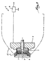
- an electrostatic rotary projector 1 of coating product comprises a rotor 2 driven in rotation by any suitable means and, in particular by an air turbine or a electric motor.
- the rotor 2 carries an elastic ring 3 which may conform to the technical teaching of EP-A-0 697 917.
- the elastic ring 3 makes it possible to make a bowl of spraying 4 of the rotor 2.
- the rotor 2 is crossed by a fixed duct 5 for supplying coating product to vicinity of a central orifice 6 for supplying the bowl 4 formed in a flange 7 extending generally perpendicular to the axis of rotation XX ′ of the rotor 2, of the ring 3 and of the bowl 4.
- the rotor 2 is made of a material electrically conductor, for example metallic, and connected by any means suitable for a high voltage generator 8.
- the ring 3 and the flange 7 are also made of materials electrically conductors, so that the high voltage from the generator 8 is transmitted to the flange 7.
- the flange 7 is therefore able to charge electrostatically, by contact, the coating product which flows on its surface when it is supplied with high voltage by generator 8 during operation of projector 1.
- the bowl 4 also includes a deflector 9 disposed opposite the outlet orifice of the conduit 5 relative to the flange 7, that is to say facing a surface 7 a , called the front face, of the flange 7.
- the deflector 9 is pierced with four conduits 10 allowing, during the cleaning phases of the bowl, the flow of a part of a solvent coming from the conduit 5 on its surface 9 a directed towards the outside and called the face before.
- the deflector 9 is immobilized with respect to the flange 7 by screws 11 passing through the flange 7 and penetrating into the rear bosses 9 b of the deflector 9.
- the piece 20 is advantageously glued to the flange 7. It is also noted that the respective shapes of the pieces 7 and 20 contribute to immobilization of the piece 20 on the flange 7 by cooperation of shapes.
- Needle-shaped metal inserts 22 are housed in eight blind holes 23 formed both in the part 20 and in the flange 7.
- Each insert 22 comprises a first end 22 a , in the shape of a point, disposed flush with the surface external 20 has the part 20 close to the spraying edge 21.
- the second end 22 b is inserted into the bottom of the hole 23 which is formed in the portion 7b of the flange 7.
- the inserts 22, which are metallic, are in permanently brought to the same electrical potential as the flange 7.
- the bowl includes several inserts 22 distributed around the axis XX 'allows to multiply the effect described above and to ensure symmetry around it this axis.
- a second series of eight inserts 25 is arranged through the part 20 and the external radial part 7 b of the flange 7, each insert 25 comprising a first end 25 a in point shape arranged in the immediate vicinity of the external part 20 a 1 of the external surface 20 a .
- the spikes 25 are inserts 25 are directed towards the rear of the bowl 4, in the direction of a cover outer surface 12 of the projector 1 shown in phantom in Figure 1.
- any object to ground can not be approached tips 25a through the hood 12 which is insulating, so that the cover limits the potential approach area of a ground object.
- Each insert 25 carries, at its second end 25 b , a head or flange 25 c capable of cooperating with a shoulder 26 a of a receiving hole 26 of the insert 25. This makes it possible to position the first end with precision 25 has the insert 25 relative to the external surface 20 a 1 of the part 20.
- a glue or resin plug 27 is advantageously disposed in the part of the bore 26 opposite the point 25 a , so that the part 20 a 2 of the external surface 20 a directed towards the axis XX 'does not have any irregularities in which the coating product could accumulate.
- an insert 28 is disposed in. the deflector 9 and comprises a first end 28 a , in the shape of a point, disposed flush with the front face 9 a of the deflector 9. If the deflector 9 is made of electrically conductive material, the insert 28 is brought to the same potential electrostatic than the flange 7, so that it is capable of generating a discharge line, as explained above with reference to the inserts 22 and 25. It should here be noted that, even if it is disposed within an electrically surface conductive raised to the high voltage through the bosses 9b, the tip of the insert 28 constitutes a privileged zone of discharge relative to the surface 9a of the deflector 9.
- the scent generated at the tips of inserts 25 and 28 are detected by the generator 8.
- the deflector 9 is made of electrically insulating material, in which case the insert 28 is brought to a floating potential.
- the tip 28 a is also used for the effluvium of the electrostatic charges drained by the insert 28 on the surface of the deflector 9.
- the insert 28 prevents the electrical capacity of the conduit 5, of its support and of the turbine associated with the rotor 2 from being discharged through the conduits 10 for flushing the front face 9 has deflector.
- the inserts 25 include a tapered tip at each end 25 a or 25 b .
- This also makes it possible to create a discharge line L "on the side of the surface 20 a 2 of the part 20 when a sphere S, at earth potential, is approached in the direction of the point 25 b .
- the ends in point 25 b avoid the creation of electric arcs or high energy discharges between the front circular edge 9 c of the deflector and an object grounded in the position of the sphere S in FIG. 5.
- the presence of the flange 25 c and the shoulder 26 a guarantees that the inserts 25 are not likely to be ejected from the bowl under the effect of the intense centrifugal forces which they undergo due to high rotation speeds of the spray bowl which can reach, or even exceed, 80,000 revolutions per minute.
- the material used for the manufacture of the flange 7 is advantageously based on aluminum, which allows it to have good dimensional stability, this property being essential when rotating the bowl at speed high.
- the material used for part 20 can be a resin based on polyoxymethylene.
- inserts 22, 25 and 28 can be made of steel or aluminum.
- the annular part 20 can also be produced in a semiconductor material, because it suffices that the part 20 has a higher resistivity than that of inserts 22 or 25 so that these constitute privileged routes of discharge.
- part 20 is made in an electrically insulating material, provision may be made for the inserts 22 and 25, or even insert 28, are produced in a semiconductor material.
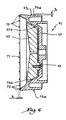
- the bowl 54 shown in Figure 6 can be mounted on the projector shown schematically in Figure 1.
- This bowl essentially comprises a flange 57 made of an electrically conductive material on which is fixed one. deflector 59 by means of several screws 61.
- This bowl differs from those of the previous embodiments essentially in that it does not include an annular piece more insulating than the flange 57, but on the contrary in that the flange 57 extends radially to the outside so as to form the spraying edge 71.
- Note 57c the outer peripheral surface of the flange 57.
- the points 72 to 75 a and 75 b constitute as many privileged zones for discharging by corona the electrical capacity constituted by the flange 57 as a whole.
- the variations in current consumption induced by the emanations, during the creation of a discharge line, in particular by approaching an object of ground, can be detected by the generator 8 mentioned with reference to the first embodiment.
- the points or pins 72, 75 a and 75 b have a height h relative to the spraying edge 71 or to the surfaces 57 c and 57 d of the order of 1 to 2 mm, which allows them to create zones discharge by fragrance without being dangerous for a user who handles the bowl 54.
- the deflector 59 can be equipped with a discharge insert by corona, or even provided, in its central part, with a point of the type of tips 72.
Landscapes
- Electrostatic Spraying Apparatus (AREA)
Claims (13)
- Sprühglocke (4) für einen rotierenden elektrostatischen Projektor (1) für Beschichtungsprodukt, wobei die Glocke einen Verteilungsflansch (7) des Produkts umfasst, der aus einem elektrisch leitendem Material hergestellt ist und während des Betriebs des Projektors auf Hochspannung gebracht wird, damit das Produkt durch Kontakt elektrostatisch aufgeladen wird,
dadurch gekennzeichnet, dass der Flansch an seinem äußeren Umfang (7b) durch ein im wesentlichen ringförmiges, aus einem elektrisch isolierenden Material hergestelltes Teil (20) aus einem elektrisch isolierendem Material begrenzt ist, das einen Zerstäubungsrand oder eine Zerstäubungskante (21) bildet, dass mindestens ein elektrisch leitender Einsatz (22, 25) für eine Stromentladung durch Entladung von einem Ende (22a, 25a, 25b) in den ringförmigen Teil in elektrischem Kontakt mit dem Flansch (7) angeordnet ist und dass das Ende (22a, 25a, 25b) des Einsatzes in Form einer sich verjüngenden Spitze ausgebildet ist und sich bis in die Nähe einer äußeren Oberfläche (20a) des ringförmigen Teils erstreckt. - Sprühglocke nach Anspruch 1, dadurch gekennzeichnet, dass der Einsatz (22, 25) teilweise in einer in dem leitenden Flansch (7) eingearbeiteten Bohrung (23, 26) aufgenommen ist.
- Sprühglocke nach einem der Ansprüche 1 oder 2 mit einem Ablenker (9) des Beschichtungsproduktstroms, der gegenüber einer Fläche (7a), genannt Vorderfläche, des Flansches (7) angeordnet ist, dadurch gekennzeichnet, dass der Ablenker mindestens ein Entladungselement (28) trägt, das sich bis zu einer äußeren Fläche (9a), genannt Vorderfläche, des Ablenkers erstreckt.
- Sprühglocke nach Anspruch 3, dadurch gekennzeichnet, dass das Entladungselement ein Einsatz (28) ist, der entsprechend der Drehachse (XX') der Glocke (4) angeordnet ist.
- Sprühglocke nach einem der vorhergehenden Ansprüche, dadurch gekennzeichnet, dass der oder die Einsätze (22, 25, 28) in Form einer Nadel ausgebildet sind und mit mindestens einem Ende (22a, 25a, 28a) in Form einer Spitze ausgerüstet sind, wobei das Ende zu der äußeren Fläche (20a, 20a1, 20a2, 9a) des ringförmigen Teils (20) oder des Ablenkers (9) versenkt ist.
- Sprühglocke nach Anspruch 5, dadurch gekennzeichnet, dass mindestens ein Einsatz (25) einen Kragen (25c) trägt, der mit einer inneren Schulter (26a) einer Aufnahme (26) des Einsatzes zusammenarbeiten kann.
- Sprühglocke nach Anspruch 5, dadurch gekennzeichnet, dass mindestens ein Einsatz (25) mit zwei Enden (25a, 25b) in Form einer Spitze ausgerüstet ist, wobei die zwei Enden zu zwei äußeren Flächen (20a1, 20a2) des ringförmigen Teils (20) versenkt sind, wobei die zwei äußeren Flächen jeweils zur Drehachse (XX') der Glocke (4) und nach außen bezüglich der Glocke gerichtet sind.
- Sprühglocke nach einem der vorhergehenden Ansprüche, dadurch gekennzeichnet, dass das Ende (22a) des Einsatzes (22) nahe der äußeren Fläche (20a) der Glocke in der Nähe des Randes oder der Kante (21) zur Zerstäubung angeordnet ist.
- Sprühglocke (54) für einen rotierenden elektrostatischen Projektor (1) für Beschichtungsprodukt, wobei die Glocke einen aus einem elektrisch leitenden Material hergestellten Verteilungsflansch (57) des Produkts umfasst, der während des Betriebs des Projektors auf Hochspannung gebracht wird, um das Produkt durch Kontakt elektrostatisch aufzuladen, dadurch gekennzeichnet, dass der Flansch auf einer äußeren Umfangsfläche (57c) in Bezug auf die Drehachse der Glocke mit einem Element zur Stromentladung durch Entladung in Form einer sich verjüngenden Spitze (75a) in einem Stück mit dem Flansch versehen ist, das sich in eine im Wesentlichen orthogonale Richtung zur äußeren Umfangsfläche erstreckt.
- Sprühglocke nach Anspruch 9, dadurch gekennzeichnet, dass sie Entladungsspitzen (75b) aufweist, die auf einer Innenfläche (57d) des Flansches (57) ausgearbeitet sind und zu einem Ablenker (59) der Glocke (54) gerichtet sind.
- Sprühglocke nach einem der Ansprüche 9 oder 10, dadurch gekennzeichnet, dass sie auf einer Zerstäubungskante (71) der Glocke vorgesehene Spitzen (72) umfasst, wobei die Spitzen eine Höhe (h) in Bezug auf die Kante aufweisen, die ihnen erlaubt, Entladungszonen durch Entladung zu erzeugen.
- Sprühglocke nach einem der vorhergehenden Ansprüche, dadurch gekennzeichnet, dass sie mehrere Entladungselemente oder -einsätze (22, 25; 72, 75a, 75b) umfasst, die regelmäßig um die Drehachse (XX') der Glocke (4; 54) verteilt sind.
- Elektrostatischer, rotierender Projektor für Beschichtungsprodukt, dadurch gekennzeichnet, dass er eine Glocke (4; 54) nach einem der vorhergehenden Ansprüche und Mittel zur elektrischen Verbindung (2, 3) des Flansches (7; 57) der Glocke mit einem Hochspannungsgenerator (8) umfasst, wobei der Generator in der Lage ist, Schwankungen des Entladungsstroms, der die Entladungselemente oder -einsätze (22, 25; 72, 75a, 75b) der Glocke passiert, zu detektieren.
Applications Claiming Priority (3)
| Application Number | Priority Date | Filing Date | Title |
|---|---|---|---|
| FR9804269A FR2776946B1 (fr) | 1998-04-01 | 1998-04-01 | Bol de pulverisation et projecteur rotatif electrostatique equipe d'un tel bol |
| FR9804269 | 1998-04-01 | ||
| PCT/FR1999/000752 WO1999049982A1 (fr) | 1998-04-01 | 1999-03-31 | Bol de pulverisation et projecteur rotatif electrostatique equipe d'un tel bol |
Publications (2)
| Publication Number | Publication Date |
|---|---|
| EP1068022A1 EP1068022A1 (de) | 2001-01-17 |
| EP1068022B1 true EP1068022B1 (de) | 2003-07-16 |
Family
ID=9524915
Family Applications (1)
| Application Number | Title | Priority Date | Filing Date |
|---|---|---|---|
| EP99910470A Expired - Lifetime EP1068022B1 (de) | 1998-04-01 | 1999-03-31 | Sprühglocke und rotationszerstäuber mit einer solchen sprühglocke |
Country Status (16)
| Country | Link |
|---|---|
| US (1) | US6347754B1 (de) |
| EP (1) | EP1068022B1 (de) |
| JP (1) | JP2002509795A (de) |
| KR (1) | KR100564289B1 (de) |
| CN (1) | CN1120056C (de) |
| AU (1) | AU2941399A (de) |
| BR (1) | BR9908740A (de) |
| CA (1) | CA2320880A1 (de) |
| DE (1) | DE69909605T2 (de) |
| ES (1) | ES2203089T3 (de) |
| FR (1) | FR2776946B1 (de) |
| HU (1) | HUP0102390A2 (de) |
| PL (1) | PL343080A1 (de) |
| TR (1) | TR200002697T2 (de) |
| TW (1) | TW429168B (de) |
| WO (1) | WO1999049982A1 (de) |
Families Citing this family (11)
| Publication number | Priority date | Publication date | Assignee | Title |
|---|---|---|---|---|
| US6889921B2 (en) * | 2002-09-30 | 2005-05-10 | Illinois Tool Works Inc. | Bell cup skirt |
| DE10324074B4 (de) * | 2003-05-27 | 2006-01-26 | Dürr Systems GmbH | Glockenteller für einen Rotationszerstäuber |
| US8031992B2 (en) | 2004-05-07 | 2011-10-04 | Finisar Corporation | Optoelectronic module and method for producing an optoelectronic module |
| GB2443431B (en) * | 2006-11-02 | 2008-12-03 | Siemens Ag | Fuel-injector nozzle |
| JP5490369B2 (ja) * | 2008-03-12 | 2014-05-14 | ランズバーグ・インダストリー株式会社 | 回転式静電塗装装置及び塗装パターン制御方法 |
| PL2903748T3 (pl) * | 2012-10-01 | 2018-03-30 | Graco Minnesota Inc. | Zespół rozpylacza do elektrostatycznego pistoletu lakierniczego |
| FR3004661B1 (fr) | 2013-04-22 | 2017-06-02 | Sames Tech | Projecteur electrostatique de produit de revetement liquide et installation de projection comprenant un tel projecteur |
| FR3012985B1 (fr) | 2013-11-12 | 2016-12-09 | Sames Tech | Projecteur electrostatique de produit de revetement et installation de projection comprenant un tel projecteur |
| USD910717S1 (en) | 2018-07-31 | 2021-02-16 | Hotstart, Inc. | Rotary atomizer |
| US20200041130A1 (en) | 2018-07-31 | 2020-02-06 | Hotstart, Inc. | Combustor Systems |
| CN109530115A (zh) * | 2019-01-10 | 2019-03-29 | 深圳浥清环保科技有限公司 | 一种静电离心雾化装置 |
Family Cites Families (15)
| Publication number | Priority date | Publication date | Assignee | Title |
|---|---|---|---|---|
| US2901178A (en) * | 1956-08-30 | 1959-08-25 | Edward O Norris | Spraying apparatus |
| FR1438510A (fr) * | 1965-03-26 | 1966-05-13 | Sames Mach Electrostat | Perfectionnements au recouvrement électrostatique |
| SE438966B (sv) * | 1978-12-04 | 1985-05-28 | Gema Ransburg Ag | Sprutanordning for pulver, med i munstycksoppningen tangentiellt inledd spridningsgas |
| BE882450A (fr) * | 1980-03-26 | 1980-07-16 | Ransburg G M B H | Dispositif de dispersion electrostatique en gerbe de substance de revetement |
| JPS5867368A (ja) * | 1981-10-16 | 1983-04-21 | Trinity Ind Corp | 静電塗装方法及びそれに用いる装置 |
| EP0094796B1 (de) * | 1982-05-13 | 1990-10-10 | National Research Development Corporation | Sprühvorrichtung |
| DE8224329U1 (de) * | 1982-08-28 | 1983-01-05 | Hermann Behr & Sohn Gmbh & Co, 7121 Ingersheim | Einrichtung zum vernebeln fluessiger farbe |
| DE3241504A1 (de) * | 1982-10-21 | 1984-04-26 | Basf Farben + Fasern Ag, 2000 Hamburg | Vorrichtung und verfahren zum elekrtostatischen ueberziehen von gegenstaenden mit fluiden |
| FR2587919B1 (fr) * | 1985-10-02 | 1988-05-27 | Sames Sa | Appareil de projection electrostatique protege contre l'apparition d'arcs electriques |
| US4737897A (en) | 1986-10-29 | 1988-04-12 | Honeywell Inc. | Regulated high voltage dc-dc converter with remotely switched output polarity control |
| DE3705815A1 (de) * | 1987-02-24 | 1988-09-01 | Kopperschmidt Mueller & Co | Elektrostatische spruehpistole |
| FR2692501B1 (fr) * | 1992-06-22 | 1995-08-04 | Sames Sa | Dispositif de projection electrostatique de produit de revetement liquide a tete de pulverisation rotative. |
| FR2698564B1 (fr) | 1992-12-01 | 1995-03-03 | Sames Sa | Dispositif de projection de produit de revêtement à élément rotatif de pulvérisation et outil pour le montage et le démontage d'un tel élément rotatif. |
| WO1996036438A1 (en) * | 1995-05-19 | 1996-11-21 | Nordson Corporation | Powder spray gun with rotary distributor |
| US5957395A (en) * | 1997-10-21 | 1999-09-28 | Illinois Tool Works Inc. | Safe charging |
-
1998
- 1998-04-01 FR FR9804269A patent/FR2776946B1/fr not_active Expired - Lifetime
-
1999
- 1999-03-26 TW TW088104799A patent/TW429168B/zh not_active IP Right Cessation
- 1999-03-31 EP EP99910470A patent/EP1068022B1/de not_active Expired - Lifetime
- 1999-03-31 BR BR9908740-5A patent/BR9908740A/pt not_active Application Discontinuation
- 1999-03-31 CA CA002320880A patent/CA2320880A1/fr not_active Abandoned
- 1999-03-31 ES ES99910470T patent/ES2203089T3/es not_active Expired - Lifetime
- 1999-03-31 CN CN99803823A patent/CN1120056C/zh not_active Expired - Fee Related
- 1999-03-31 PL PL99343080A patent/PL343080A1/xx unknown
- 1999-03-31 HU HU0102390A patent/HUP0102390A2/hu unknown
- 1999-03-31 DE DE69909605T patent/DE69909605T2/de not_active Expired - Lifetime
- 1999-03-31 WO PCT/FR1999/000752 patent/WO1999049982A1/fr not_active Ceased
- 1999-03-31 KR KR1020007009618A patent/KR100564289B1/ko not_active Expired - Fee Related
- 1999-03-31 AU AU29413/99A patent/AU2941399A/en not_active Abandoned
- 1999-03-31 JP JP2000540940A patent/JP2002509795A/ja active Pending
- 1999-03-31 US US09/647,198 patent/US6347754B1/en not_active Expired - Lifetime
- 1999-03-31 TR TR2000/02697T patent/TR200002697T2/xx unknown
Also Published As
| Publication number | Publication date |
|---|---|
| KR100564289B1 (ko) | 2006-03-29 |
| FR2776946B1 (fr) | 2000-05-26 |
| DE69909605D1 (de) | 2003-08-21 |
| CN1120056C (zh) | 2003-09-03 |
| PL343080A1 (en) | 2001-07-30 |
| KR20010041463A (ko) | 2001-05-25 |
| US6347754B1 (en) | 2002-02-19 |
| TW429168B (en) | 2001-04-11 |
| ES2203089T3 (es) | 2004-04-01 |
| AU2941399A (en) | 1999-10-18 |
| DE69909605T2 (de) | 2004-04-15 |
| CN1292731A (zh) | 2001-04-25 |
| EP1068022A1 (de) | 2001-01-17 |
| HUP0102390A2 (hu) | 2001-10-28 |
| CA2320880A1 (fr) | 1999-10-07 |
| JP2002509795A (ja) | 2002-04-02 |
| BR9908740A (pt) | 2000-11-21 |
| FR2776946A1 (fr) | 1999-10-08 |
| WO1999049982A1 (fr) | 1999-10-07 |
| TR200002697T2 (tr) | 2000-12-21 |
Similar Documents
| Publication | Publication Date | Title |
|---|---|---|
| EP1068022B1 (de) | Sprühglocke und rotationszerstäuber mit einer solchen sprühglocke | |
| FR2692501A1 (fr) | Dispositif de projection électrostatique de produit de revêtement liquide à tête de pulvérisation rotative. | |
| EP0574305B1 (de) | Vorrichtung zum elektrostatischen Sprühen von pulverformigen Stoffen mit einem rotierenden Ionisierungskopf | |
| FR2762237A1 (fr) | Dispositif de pulverisation a atomisation rotative electrostatique | |
| EP0697917B1 (de) | Farbspritzvorrichtung mit rotierendem zerstäubungselement und werkzeug zum montieren und demontieren dieses elements | |
| EP1480756A1 (de) | Rotationszerstäuber für beschichtungsmittel | |
| EP2988877B1 (de) | Elektrostatische sprühvorrichtung zum versprühen eines beschichtungsflüssigkeitsprodukts und sprühanlage mit solch einer sprühvorrichtung | |
| EP0276849B1 (de) | Rotierender Brecher mit geschützten Schleuderradschaufeln | |
| FR2694924A1 (fr) | Distributeur à roue à alvéoles pour produits en vrac granuleux. | |
| EP0454548B1 (de) | Vorrichtung zum Fliehkraftzerstäuben eines Beschichtungsproduktes, insbesondere zum elektrostatischen Sprühauftragen | |
| FR2598636A1 (fr) | Atomiseur rotatif pour la projection de peintures liquides et analogues | |
| JP3411815B2 (ja) | 回転霧化頭型塗装装置 | |
| EP0552089B1 (de) | Vorrichtung zur Zerstäubung einer Flüssigkeit, insbesondere eines flüssigen Brennstoffes in einem Brenner | |
| EP3068544A1 (de) | Elektrostatische sprühvorrichtung für beschichtungsprodukt und projektionsanordnung mit solch einer sprühvorrichtung | |
| JP3274613B2 (ja) | 回転霧化頭型塗装装置 | |
| EP3456634A1 (de) | Flügel mit einer vorderkante und verfahren zur vermeindung von verstopfung der löscher in der vorderkante | |
| WO1991007230A1 (fr) | Electrocyclone pour le depoussierage de gaz | |
| WO2013153205A1 (fr) | Projecteur rotatif et methode de pulverisation d'un produit de revetement | |
| FR2791279A1 (fr) | Dispositif de projection d'un produit de revetement en poudre et organe de projection equipant un tel dispositif | |
| FR2483326A1 (fr) | Imprimante a jet de gouttelettes pilotees par deviation electrostatique | |
| BE675468A (de) | ||
| FR2723113A1 (fr) | Ensemble de suppression de marques de pate a macher adherant sur un sol | |
| WO1994005427A1 (fr) | Dispositif d'introduction ou d'alimentation d'un materiau dans un broyeur a axe vertical et broyeur equipe de ce dispositif | |
| EP4512532A1 (de) | Sprühvorrichtung und rotationszerstäuber für beschichtungsmittel mit solch einer sprühvorrichtung | |
| FR2706328A1 (fr) | Projecteur électrostatique de produit de revêtement pulvérulent comportant une tête de projection rotative. |
Legal Events
| Date | Code | Title | Description |
|---|---|---|---|
| PUAI | Public reference made under article 153(3) epc to a published international application that has entered the european phase |
Free format text: ORIGINAL CODE: 0009012 |
|
| 17P | Request for examination filed |
Effective date: 20000811 |
|
| AK | Designated contracting states |
Kind code of ref document: A1 Designated state(s): BE CH DE ES FR GB GR IT LI NL PT SE |
|
| AX | Request for extension of the european patent |
Free format text: RO PAYMENT 20000811 |
|
| RAP1 | Party data changed (applicant data changed or rights of an application transferred) |
Owner name: SAMES TECHNOLOGIES |
|
| GRAH | Despatch of communication of intention to grant a patent |
Free format text: ORIGINAL CODE: EPIDOS IGRA |
|
| GRAH | Despatch of communication of intention to grant a patent |
Free format text: ORIGINAL CODE: EPIDOS IGRA |
|
| GRAH | Despatch of communication of intention to grant a patent |
Free format text: ORIGINAL CODE: EPIDOS IGRA |
|
| GRAA | (expected) grant |
Free format text: ORIGINAL CODE: 0009210 |
|
| AK | Designated contracting states |
Designated state(s): BE CH DE ES FR GB GR IT LI NL PT SE |
|
| AX | Request for extension of the european patent |
Extension state: RO |
|
| PG25 | Lapsed in a contracting state [announced via postgrant information from national office to epo] |
Ref country code: NL Free format text: LAPSE BECAUSE OF FAILURE TO SUBMIT A TRANSLATION OF THE DESCRIPTION OR TO PAY THE FEE WITHIN THE PRESCRIBED TIME-LIMIT Effective date: 20030716 |
|
| REG | Reference to a national code |
Ref country code: GB Ref legal event code: FG4D Free format text: NOT ENGLISH |
|
| REG | Reference to a national code |
Ref country code: CH Ref legal event code: EP |
|
| REF | Corresponds to: |
Ref document number: 69909605 Country of ref document: DE Date of ref document: 20030821 Kind code of ref document: P |
|
| REG | Reference to a national code |
Ref country code: SE Ref legal event code: TRGR |
|
| PG25 | Lapsed in a contracting state [announced via postgrant information from national office to epo] |
Ref country code: GR Free format text: LAPSE BECAUSE OF FAILURE TO SUBMIT A TRANSLATION OF THE DESCRIPTION OR TO PAY THE FEE WITHIN THE PRESCRIBED TIME-LIMIT Effective date: 20031016 |
|
| GBT | Gb: translation of ep patent filed (gb section 77(6)(a)/1977) |
Effective date: 20031015 |
|
| NLV1 | Nl: lapsed or annulled due to failure to fulfill the requirements of art. 29p and 29m of the patents act | ||
| PG25 | Lapsed in a contracting state [announced via postgrant information from national office to epo] |
Ref country code: PT Free format text: LAPSE BECAUSE OF FAILURE TO SUBMIT A TRANSLATION OF THE DESCRIPTION OR TO PAY THE FEE WITHIN THE PRESCRIBED TIME-LIMIT Effective date: 20031216 |
|
| PG25 | Lapsed in a contracting state [announced via postgrant information from national office to epo] |
Ref country code: LI Free format text: LAPSE BECAUSE OF NON-PAYMENT OF DUE FEES Effective date: 20040331 Ref country code: CH Free format text: LAPSE BECAUSE OF NON-PAYMENT OF DUE FEES Effective date: 20040331 Ref country code: BE Free format text: LAPSE BECAUSE OF NON-PAYMENT OF DUE FEES Effective date: 20040331 |
|
| REG | Reference to a national code |
Ref country code: ES Ref legal event code: FG2A Ref document number: 2203089 Country of ref document: ES Kind code of ref document: T3 |
|
| PLBE | No opposition filed within time limit |
Free format text: ORIGINAL CODE: 0009261 |
|
| STAA | Information on the status of an ep patent application or granted ep patent |
Free format text: STATUS: NO OPPOSITION FILED WITHIN TIME LIMIT |
|
| 26N | No opposition filed |
Effective date: 20040419 |
|
| BERE | Be: lapsed |
Owner name: *SAMES TECHNOLOGIES Effective date: 20040331 |
|
| REG | Reference to a national code |
Ref country code: CH Ref legal event code: PL |
|
| PGFP | Annual fee paid to national office [announced via postgrant information from national office to epo] |
Ref country code: ES Payment date: 20060317 Year of fee payment: 8 |
|
| PGFP | Annual fee paid to national office [announced via postgrant information from national office to epo] |
Ref country code: IT Payment date: 20060331 Year of fee payment: 8 |
|
| GBPC | Gb: european patent ceased through non-payment of renewal fee |
Effective date: 20070331 |
|
| PGFP | Annual fee paid to national office [announced via postgrant information from national office to epo] |
Ref country code: SE Payment date: 20060217 Year of fee payment: 8 |
|
| PG25 | Lapsed in a contracting state [announced via postgrant information from national office to epo] |
Ref country code: GB Free format text: LAPSE BECAUSE OF NON-PAYMENT OF DUE FEES Effective date: 20070331 |
|
| REG | Reference to a national code |
Ref country code: ES Ref legal event code: FD2A Effective date: 20070402 |
|
| PG25 | Lapsed in a contracting state [announced via postgrant information from national office to epo] |
Ref country code: SE Free format text: LAPSE BECAUSE OF NON-PAYMENT OF DUE FEES Effective date: 20070401 |
|
| PG25 | Lapsed in a contracting state [announced via postgrant information from national office to epo] |
Ref country code: ES Free format text: LAPSE BECAUSE OF NON-PAYMENT OF DUE FEES Effective date: 20070402 |
|
| PGFP | Annual fee paid to national office [announced via postgrant information from national office to epo] |
Ref country code: GB Payment date: 20060307 Year of fee payment: 8 |
|
| PG25 | Lapsed in a contracting state [announced via postgrant information from national office to epo] |
Ref country code: IT Free format text: LAPSE BECAUSE OF NON-PAYMENT OF DUE FEES Effective date: 20070331 |
|
| PGFP | Annual fee paid to national office [announced via postgrant information from national office to epo] |
Ref country code: DE Payment date: 20140311 Year of fee payment: 16 |
|
| PGFP | Annual fee paid to national office [announced via postgrant information from national office to epo] |
Ref country code: FR Payment date: 20140227 Year of fee payment: 16 |
|
| REG | Reference to a national code |
Ref country code: DE Ref legal event code: R119 Ref document number: 69909605 Country of ref document: DE |
|
| REG | Reference to a national code |
Ref country code: FR Ref legal event code: ST Effective date: 20151130 |
|
| PG25 | Lapsed in a contracting state [announced via postgrant information from national office to epo] |
Ref country code: DE Free format text: LAPSE BECAUSE OF NON-PAYMENT OF DUE FEES Effective date: 20151001 |
|
| PG25 | Lapsed in a contracting state [announced via postgrant information from national office to epo] |
Ref country code: FR Free format text: LAPSE BECAUSE OF NON-PAYMENT OF DUE FEES Effective date: 20150331 |