EP1068942B1 - Method of spreading a sheet on a frame member and method of manufacturing a chair by the sheet spreading method - Google Patents
Method of spreading a sheet on a frame member and method of manufacturing a chair by the sheet spreading method Download PDFInfo
- Publication number
- EP1068942B1 EP1068942B1 EP99113839A EP99113839A EP1068942B1 EP 1068942 B1 EP1068942 B1 EP 1068942B1 EP 99113839 A EP99113839 A EP 99113839A EP 99113839 A EP99113839 A EP 99113839A EP 1068942 B1 EP1068942 B1 EP 1068942B1
- Authority
- EP
- European Patent Office
- Prior art keywords
- sheet
- frame member
- metal mold
- spreading
- resin
- Prior art date
- Legal status (The legal status is an assumption and is not a legal conclusion. Google has not performed a legal analysis and makes no representation as to the accuracy of the status listed.)
- Expired - Lifetime
Links
Images


Classifications
-
- A—HUMAN NECESSITIES
- A47—FURNITURE; DOMESTIC ARTICLES OR APPLIANCES; COFFEE MILLS; SPICE MILLS; SUCTION CLEANERS IN GENERAL
- A47C—CHAIRS; SOFAS; BEDS
- A47C7/00—Parts, details, or accessories of chairs or stools
- A47C7/02—Seat parts
- A47C7/28—Seat parts with tensioned springs, e.g. of flat type
- A47C7/282—Seat parts with tensioned springs, e.g. of flat type with mesh-like supports, e.g. elastomeric membranes
-
- A—HUMAN NECESSITIES
- A47—FURNITURE; DOMESTIC ARTICLES OR APPLIANCES; COFFEE MILLS; SPICE MILLS; SUCTION CLEANERS IN GENERAL
- A47C—CHAIRS; SOFAS; BEDS
- A47C31/00—Details or accessories for chairs, beds, or the like, not provided for in other groups of this subclass, e.g. upholstery fasteners, mattress protectors, stretching devices for mattress nets
- A47C31/02—Upholstery attaching means
-
- B—PERFORMING OPERATIONS; TRANSPORTING
- B29—WORKING OF PLASTICS; WORKING OF SUBSTANCES IN A PLASTIC STATE IN GENERAL
- B29C—SHAPING OR JOINING OF PLASTICS; SHAPING OF MATERIAL IN A PLASTIC STATE, NOT OTHERWISE PROVIDED FOR; AFTER-TREATMENT OF THE SHAPED PRODUCTS, e.g. REPAIRING
- B29C39/00—Shaping by casting, i.e. introducing the moulding material into a mould or between confining surfaces without significant moulding pressure; Apparatus therefor
- B29C39/02—Shaping by casting, i.e. introducing the moulding material into a mould or between confining surfaces without significant moulding pressure; Apparatus therefor for making articles of definite length, i.e. discrete articles
- B29C39/10—Shaping by casting, i.e. introducing the moulding material into a mould or between confining surfaces without significant moulding pressure; Apparatus therefor for making articles of definite length, i.e. discrete articles incorporating preformed parts or layers, e.g. casting around inserts or for coating articles
-
- B—PERFORMING OPERATIONS; TRANSPORTING
- B29—WORKING OF PLASTICS; WORKING OF SUBSTANCES IN A PLASTIC STATE IN GENERAL
- B29C—SHAPING OR JOINING OF PLASTICS; SHAPING OF MATERIAL IN A PLASTIC STATE, NOT OTHERWISE PROVIDED FOR; AFTER-TREATMENT OF THE SHAPED PRODUCTS, e.g. REPAIRING
- B29C41/00—Shaping by coating a mould, core or other substrate, i.e. by depositing material and stripping-off the shaped article; Apparatus therefor
- B29C41/02—Shaping by coating a mould, core or other substrate, i.e. by depositing material and stripping-off the shaped article; Apparatus therefor for making articles of definite length, i.e. discrete articles
- B29C41/08—Coating a former, core or other substrate by spraying or fluidisation, e.g. spraying powder
-
- B—PERFORMING OPERATIONS; TRANSPORTING
- B29—WORKING OF PLASTICS; WORKING OF SUBSTANCES IN A PLASTIC STATE IN GENERAL
- B29C—SHAPING OR JOINING OF PLASTICS; SHAPING OF MATERIAL IN A PLASTIC STATE, NOT OTHERWISE PROVIDED FOR; AFTER-TREATMENT OF THE SHAPED PRODUCTS, e.g. REPAIRING
- B29C41/00—Shaping by coating a mould, core or other substrate, i.e. by depositing material and stripping-off the shaped article; Apparatus therefor
- B29C41/02—Shaping by coating a mould, core or other substrate, i.e. by depositing material and stripping-off the shaped article; Apparatus therefor for making articles of definite length, i.e. discrete articles
- B29C41/08—Coating a former, core or other substrate by spraying or fluidisation, e.g. spraying powder
- B29C41/10—Coating a former, core or other substrate by spraying or fluidisation, e.g. spraying powder by fluidisation
-
- B—PERFORMING OPERATIONS; TRANSPORTING
- B29—WORKING OF PLASTICS; WORKING OF SUBSTANCES IN A PLASTIC STATE IN GENERAL
- B29C—SHAPING OR JOINING OF PLASTICS; SHAPING OF MATERIAL IN A PLASTIC STATE, NOT OTHERWISE PROVIDED FOR; AFTER-TREATMENT OF THE SHAPED PRODUCTS, e.g. REPAIRING
- B29C65/00—Joining or sealing of preformed parts, e.g. welding of plastics materials; Apparatus therefor
- B29C65/48—Joining or sealing of preformed parts, e.g. welding of plastics materials; Apparatus therefor using adhesives, i.e. using supplementary joining material; solvent bonding
-
- B—PERFORMING OPERATIONS; TRANSPORTING
- B29—WORKING OF PLASTICS; WORKING OF SUBSTANCES IN A PLASTIC STATE IN GENERAL
- B29C—SHAPING OR JOINING OF PLASTICS; SHAPING OF MATERIAL IN A PLASTIC STATE, NOT OTHERWISE PROVIDED FOR; AFTER-TREATMENT OF THE SHAPED PRODUCTS, e.g. REPAIRING
- B29C66/00—General aspects of processes or apparatus for joining preformed parts
- B29C66/01—General aspects dealing with the joint area or with the area to be joined
- B29C66/05—Particular design of joint configurations
- B29C66/10—Particular design of joint configurations particular design of the joint cross-sections
- B29C66/11—Joint cross-sections comprising a single joint-segment, i.e. one of the parts to be joined comprising a single joint-segment in the joint cross-section
- B29C66/112—Single lapped joints
-
- B—PERFORMING OPERATIONS; TRANSPORTING
- B29—WORKING OF PLASTICS; WORKING OF SUBSTANCES IN A PLASTIC STATE IN GENERAL
- B29C—SHAPING OR JOINING OF PLASTICS; SHAPING OF MATERIAL IN A PLASTIC STATE, NOT OTHERWISE PROVIDED FOR; AFTER-TREATMENT OF THE SHAPED PRODUCTS, e.g. REPAIRING
- B29C66/00—General aspects of processes or apparatus for joining preformed parts
- B29C66/01—General aspects dealing with the joint area or with the area to be joined
- B29C66/05—Particular design of joint configurations
- B29C66/10—Particular design of joint configurations particular design of the joint cross-sections
- B29C66/11—Joint cross-sections comprising a single joint-segment, i.e. one of the parts to be joined comprising a single joint-segment in the joint cross-section
- B29C66/112—Single lapped joints
- B29C66/1122—Single lap to lap joints, i.e. overlap joints
-
- B—PERFORMING OPERATIONS; TRANSPORTING
- B29—WORKING OF PLASTICS; WORKING OF SUBSTANCES IN A PLASTIC STATE IN GENERAL
- B29C—SHAPING OR JOINING OF PLASTICS; SHAPING OF MATERIAL IN A PLASTIC STATE, NOT OTHERWISE PROVIDED FOR; AFTER-TREATMENT OF THE SHAPED PRODUCTS, e.g. REPAIRING
- B29C66/00—General aspects of processes or apparatus for joining preformed parts
- B29C66/01—General aspects dealing with the joint area or with the area to be joined
- B29C66/05—Particular design of joint configurations
- B29C66/10—Particular design of joint configurations particular design of the joint cross-sections
- B29C66/13—Single flanged joints; Fin-type joints; Single hem joints; Edge joints; Interpenetrating fingered joints; Other specific particular designs of joint cross-sections not provided for in groups B29C66/11 - B29C66/12
- B29C66/131—Single flanged joints, i.e. one of the parts to be joined being rigid and flanged in the joint area
-
- B—PERFORMING OPERATIONS; TRANSPORTING
- B29—WORKING OF PLASTICS; WORKING OF SUBSTANCES IN A PLASTIC STATE IN GENERAL
- B29C—SHAPING OR JOINING OF PLASTICS; SHAPING OF MATERIAL IN A PLASTIC STATE, NOT OTHERWISE PROVIDED FOR; AFTER-TREATMENT OF THE SHAPED PRODUCTS, e.g. REPAIRING
- B29C66/00—General aspects of processes or apparatus for joining preformed parts
- B29C66/50—General aspects of joining tubular articles; General aspects of joining long products, i.e. bars or profiled elements; General aspects of joining single elements to tubular articles, hollow articles or bars; General aspects of joining several hollow-preforms to form hollow or tubular articles
- B29C66/51—Joining tubular articles, profiled elements or bars; Joining single elements to tubular articles, hollow articles or bars; Joining several hollow-preforms to form hollow or tubular articles
- B29C66/53—Joining single elements to tubular articles, hollow articles or bars
- B29C66/534—Joining single elements to open ends of tubular or hollow articles or to the ends of bars
- B29C66/5346—Joining single elements to open ends of tubular or hollow articles or to the ends of bars said single elements being substantially flat
-
- B—PERFORMING OPERATIONS; TRANSPORTING
- B29—WORKING OF PLASTICS; WORKING OF SUBSTANCES IN A PLASTIC STATE IN GENERAL
- B29C—SHAPING OR JOINING OF PLASTICS; SHAPING OF MATERIAL IN A PLASTIC STATE, NOT OTHERWISE PROVIDED FOR; AFTER-TREATMENT OF THE SHAPED PRODUCTS, e.g. REPAIRING
- B29C2791/00—Shaping characteristics in general
- B29C2791/001—Shaping in several steps
-
- B—PERFORMING OPERATIONS; TRANSPORTING
- B29—WORKING OF PLASTICS; WORKING OF SUBSTANCES IN A PLASTIC STATE IN GENERAL
- B29C—SHAPING OR JOINING OF PLASTICS; SHAPING OF MATERIAL IN A PLASTIC STATE, NOT OTHERWISE PROVIDED FOR; AFTER-TREATMENT OF THE SHAPED PRODUCTS, e.g. REPAIRING
- B29C65/00—Joining or sealing of preformed parts, e.g. welding of plastics materials; Apparatus therefor
- B29C65/48—Joining or sealing of preformed parts, e.g. welding of plastics materials; Apparatus therefor using adhesives, i.e. using supplementary joining material; solvent bonding
- B29C65/4805—Joining or sealing of preformed parts, e.g. welding of plastics materials; Apparatus therefor using adhesives, i.e. using supplementary joining material; solvent bonding characterised by the type of adhesives
- B29C65/481—Non-reactive adhesives, e.g. physically hardening adhesives
- B29C65/4815—Hot melt adhesives, e.g. thermoplastic adhesives
-
- B—PERFORMING OPERATIONS; TRANSPORTING
- B29—WORKING OF PLASTICS; WORKING OF SUBSTANCES IN A PLASTIC STATE IN GENERAL
- B29C—SHAPING OR JOINING OF PLASTICS; SHAPING OF MATERIAL IN A PLASTIC STATE, NOT OTHERWISE PROVIDED FOR; AFTER-TREATMENT OF THE SHAPED PRODUCTS, e.g. REPAIRING
- B29C65/00—Joining or sealing of preformed parts, e.g. welding of plastics materials; Apparatus therefor
- B29C65/48—Joining or sealing of preformed parts, e.g. welding of plastics materials; Apparatus therefor using adhesives, i.e. using supplementary joining material; solvent bonding
- B29C65/486—Joining or sealing of preformed parts, e.g. welding of plastics materials; Apparatus therefor using adhesives, i.e. using supplementary joining material; solvent bonding characterised by their physical form being non-liquid, e.g. in the form of granules or powders
-
- B—PERFORMING OPERATIONS; TRANSPORTING
- B29—WORKING OF PLASTICS; WORKING OF SUBSTANCES IN A PLASTIC STATE IN GENERAL
- B29C—SHAPING OR JOINING OF PLASTICS; SHAPING OF MATERIAL IN A PLASTIC STATE, NOT OTHERWISE PROVIDED FOR; AFTER-TREATMENT OF THE SHAPED PRODUCTS, e.g. REPAIRING
- B29C66/00—General aspects of processes or apparatus for joining preformed parts
- B29C66/80—General aspects of machine operations or constructions and parts thereof
- B29C66/83—General aspects of machine operations or constructions and parts thereof characterised by the movement of the joining or pressing tools
- B29C66/832—Reciprocating joining or pressing tools
-
- B—PERFORMING OPERATIONS; TRANSPORTING
- B29—WORKING OF PLASTICS; WORKING OF SUBSTANCES IN A PLASTIC STATE IN GENERAL
- B29L—INDEXING SCHEME ASSOCIATED WITH SUBCLASS B29C, RELATING TO PARTICULAR ARTICLES
- B29L2007/00—Flat articles, e.g. films or sheets
- B29L2007/008—Wide strips, e.g. films, webs
-
- B—PERFORMING OPERATIONS; TRANSPORTING
- B29—WORKING OF PLASTICS; WORKING OF SUBSTANCES IN A PLASTIC STATE IN GENERAL
- B29L—INDEXING SCHEME ASSOCIATED WITH SUBCLASS B29C, RELATING TO PARTICULAR ARTICLES
- B29L2012/00—Frames
-
- Y—GENERAL TAGGING OF NEW TECHNOLOGICAL DEVELOPMENTS; GENERAL TAGGING OF CROSS-SECTIONAL TECHNOLOGIES SPANNING OVER SEVERAL SECTIONS OF THE IPC; TECHNICAL SUBJECTS COVERED BY FORMER USPC CROSS-REFERENCE ART COLLECTIONS [XRACs] AND DIGESTS
- Y10—TECHNICAL SUBJECTS COVERED BY FORMER USPC
- Y10T—TECHNICAL SUBJECTS COVERED BY FORMER US CLASSIFICATION
- Y10T29/00—Metal working
- Y10T29/48—Upholstered article making
- Y10T29/481—Method
-
- Y—GENERAL TAGGING OF NEW TECHNOLOGICAL DEVELOPMENTS; GENERAL TAGGING OF CROSS-SECTIONAL TECHNOLOGIES SPANNING OVER SEVERAL SECTIONS OF THE IPC; TECHNICAL SUBJECTS COVERED BY FORMER USPC CROSS-REFERENCE ART COLLECTIONS [XRACs] AND DIGESTS
- Y10—TECHNICAL SUBJECTS COVERED BY FORMER USPC
- Y10T—TECHNICAL SUBJECTS COVERED BY FORMER US CLASSIFICATION
- Y10T29/00—Metal working
- Y10T29/49—Method of mechanical manufacture
- Y10T29/49826—Assembling or joining
- Y10T29/49863—Assembling or joining with prestressing of part
- Y10T29/49867—Assembling or joining with prestressing of part of skin on frame member
-
- Y—GENERAL TAGGING OF NEW TECHNOLOGICAL DEVELOPMENTS; GENERAL TAGGING OF CROSS-SECTIONAL TECHNOLOGIES SPANNING OVER SEVERAL SECTIONS OF THE IPC; TECHNICAL SUBJECTS COVERED BY FORMER USPC CROSS-REFERENCE ART COLLECTIONS [XRACs] AND DIGESTS
- Y10—TECHNICAL SUBJECTS COVERED BY FORMER USPC
- Y10T—TECHNICAL SUBJECTS COVERED BY FORMER US CLASSIFICATION
- Y10T29/00—Metal working
- Y10T29/49—Method of mechanical manufacture
- Y10T29/49826—Assembling or joining
- Y10T29/49885—Assembling or joining with coating before or during assembling
Definitions
- the invention relates to a method of spreading a sheet on a frame-like member such as a core member of a chair seat.
- the former discloses that by inserting a steel wire into each of two opposite sides of a wire mesh, and attaching coil springs having hooks at both ends, with one hook to the steel wire and the other hook to the wire mesh, the wire mesh is spread with a prescribed tension charged against it, by taking advantage of the energizing force of the coil springs.
- a wire mesh is spread by inserting an adapter plate into each of two opposite sides of the wire mesh and then screwing or rivet caulking the adapter plates onto the metal frame while keeping a prescribed tension charged against the wire mesh.
- edge member is apt to be in an uneven finished state and thus, might come off easily.
- an object of the invention is to provide a method of spreading a sheet on a frame member, which prevents an uneven tension charged against the spread sheet, and by reducing the number of parts necessary for the spreading, enables a more economical sheet spreading process.
- Another object of the invention is to provide a method of easily forming a protective member (equivalent to an edge member) for protecting the frame member.
- a further object of the invention is to apply the above sheet spreading method and protective member forming method to the seat and the backrest of a chair.
- a sheet spreading method of the invention placed on a metal mold having a recess corresponding to the shape of a frame member formed therein and a cooling device attached thereto, is a sheet larger than needed for spreading it on the frame member.
- the sheet is clamped to the metal mold in at least four directions.
- a molten coating of thermoplastic resin is then formed on the surface of the frame member.
- the process of spreading a sheet on the frame member is completed when the frame member is released from the clamping and taken out of the metal mold. Since the attached sheet is larger than needed, the excess of the sheet is removed by trimming along the periphery either before or after taking the frame member out of the metal mold.
- the ultimate tension charged against the spread sheet depends on the shape of the frame member, the ultimate tension is thus controllable by adjusting the frame member's shape.
- the method of the invention it is possible to spread a sheet on a frame member with an even tension charged against by means of simple structures, such as an aforementioned metal mold and clamps, and of a simple process of forming a coating. Moreover, the metal mold and the clamps are reusable when the shape of the frame member is the same. Therefore, if the present method is employed to spread a sheet on a large number of frame members, the number of necessary elements per frame member can be relatively reduced.
- the order of two processes i.e. clamping a sheet and forming a coating on the frame member, is decided in accordance with the hardenability of the coating because the coating should be molten at least at the time of fitting the frame member into the recess. Specifically, if the coating hardens in a short time, the sheet is clamped first and then the coatings formed on the frame member, which is promptly fit into the recess. If the coating takes time to harden, oppositely, either process may be performed first.
- the frame member is made of metal
- the sheet is a resin mesh or a wire mesh
- the coating is formed by melting and making a powder resin adhere to a preheated frame member.
- the frame member is preheated in order for the powder resin to melt and adhere, the sheet will not melt when the frame member is pressed into the recess if the sheet is a wire mesh.
- polyester which is heat-resistant up until 230°C, is employed as a resin, the problem of melting the sheet is avoidable so long as the temperature of the frame member is kept below 230°C (for example 200°C).
- a pre-heated frame member is placed in a flow dipping tank in which powdered resin is suspended in order to make the resin adhere to the frame member.
- the powder resin melts and adheres to the frame member, and thus the coating is formed making the whole sheet spreading process quite simple.
- powder resin is sprinkled in the recess before clamping the sheet on the metal mold.
- the powder resin melts and penetrates the sheet, and thus, surface treatment of the sheet is performed.
- the part of the sheet surrounding the frame member is covered with an even resin coating, thereby producing an equal finished state of surface treatment to every product.
- the thickness of the coating is determined to ensure that by the time of removing the frame member from the metal mold the resin has collected like beading along the border line between the sheet and the frame member. Doing so prevents the sheet from easily coming off on the border line and enables the sheet to be charged with a higher tension.
- the sheet spreading method of the invention it is possible to spread, with an even tension charged against it, a sheet on a frame member. Therefore, if the method is applied to the seat or the backrest of a chair, nondirectional flexibility is obtained and thus, such a chair is comfortable to sit on.
- a cloth covering When the invention is applied to the seat or the backrest of a chair, a cloth covering may be employed as the sheet or arranged under the wire mesh, enabling the cloth covering also to be spreadable. Further, if the recess in the metal mold is formed corresponding to the required surface shape of the cloth covering, and in addition to the cloth covering, a urethane foam cushion and a sheet (a mesh is preferable) are laid in this order on the metal mold, those being spreadable at one time, a simpler process of forming a cushioned chair seat or backrest by spreading is enabled.
- Another aspect of the invention is a method of forming a protective member for protecting a frame member, which comprises of forming a protective member of a synthetic resin wrapping from the periphery of the frame member to the border line between the frame member and the sheet by injection molding of synthetic resin after putting the frame member, with the sheet already spread, into the metal mold for injection molding.
- This method extremely simplifies the protective member forming process. Since the protective member is formed integrally with the frame member, in addition to having a good finished appearance, its adhesion to the frame member is quite strong, thus the protective member does not come off or break easily from the frame member.
- the above protective member is especially advantageous.
- a seat or a backrest having a protective member formed around its core member is easily manufactured.
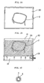
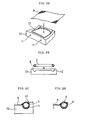
- FIGS. 1A through 1C and FIGS. 2A through 2D show the process of spreading a mesh on a core member 2 of a chair backrest by the method of spreading a sheet according to the invention.
- the core member 2 is prepared by bending a pipe and welding the same to form a frame member.
- the core member 2 is heated to around 200°C in a furnace 20 as shown in FIG. 1A and placed in a flow dipping tank 30 as shown in FIG. 1B.
- the flow dipping tank 30 comprises a powder resin suspension chamber 31 filled with powdered thermoplastic resin 36 ( hereinafter referred to as "powder resin 36") and a pressurized air chamber 32 into which air is introduced from the outside.
- FIG. 1C shows a cross section of the core member 2 to which the powder resin 36 has adhered.
- a coating 6 of the powder resin 36 is formed on the surface of the pipe 4 which constitutes the core member 2.
- the coating 6 is formed with a thickness of about 500 ⁇ m or more.
- a mesh 8 is placed on a metal mold 10.
- the mesh 8 is cut into a rectangular which is one size larger than the core member 2.
- a recess 12 whose shape corresponds to that of the core member 2 is formed in the top side of the metal mold 10, which is provided with a cooling device for cooling the metal mold 10.
- a cooling water circulation channel along the recess 12, through which cooling water is circulated in order to cool the metal mold 10.
- FIG. 2A shows a cooling water inlet 11 for pouring cooling water into the cooling water circulation channel and a cooling water outlet 13 for discharging the water whose temperature has been raised due to being circulated in the cooling water circulation channel.
- FIG. 3 is a plan view of the metal mold 10, showing the state of the core member 2 being put into the recess 12.
- the metal mold 10 is provided with six clamp handles 41 for clamping the mesh 8 and four clamp handles 43 for pressing the core member 2 against the metal mold 10.
- Numeral 45 represents a rubber frame
- numeral 47 represents the position where the mesh 8 is placed.
- the clamp handles 41 are designed to press the mesh 8 on the rubber frame 45, which enables a tight clamping of the mesh 8.
- FIG. 4 is a side elevational view taken from the right side of FIG.3.
- the mesh 8 which is sandwiched by the core member 2 and the metal mold 10, transforms in accordance with the shape of the recess 12 in the metal mold 10 with a tension charged against, and at the same time part of the resin which forms the coating 6 adhering to the surface of the core member 2 penetrates the mesh 8.
- the mesh 8 may be clamped to the metal mold 10 with a prescribed tension charged against.
- One of the methods of charging a tension against the mesh 8 is to firstly clamp one of the opposite two sides of the mesh 8, secondly pull the other side away from the above clamped side, thereby charging a tension, and finally clamp the other side.
- FIGS. 5A through 5F illustrate this process schematically.
- the core member 52 of the chair seat is formed as a frame member, as shown in FIG. 5A, by bending a sheet metal to a L-shaped cross section, further bending the above bent metal 54 to an almost square shape, and then welding the same. Since the core member 52 is heated to around 200°C and put into a flow dipping tank filled with powder resin, the same as the core member 2, a resin coating 6 with a thickness of about 500 ⁇ m or more is formed on the surface as shown in FIG. 5B.
- a mesh 58 is placed on a metal mold 60 having an inner surface 62 formed in accordance with the shape of the core member 52 and is clamped.
- the core member 52 is pressed against the metal mold 60 (FIG. 5D)
- part of the resin which forms the coating 6 penetrates the mesh 8.
- the coating 6 becomes solid by cooling, and the spreading process is completed (FIGS. 5E, 5F).
- the backrest and the seat of a chair which are formed by spreading the meshes 8 and 58 on the core members 2 and 52, respectively, according to the above described method have nondirectional flexibility and such a chair is comfortable to sit on.
- the recess 12 in the metal mold 10 in accordance with the required surface shape of a cloth covering 72 of the backrest and clamp the cloth covering 72 and the mesh 8 with a cushion 70 between them.
- spreading and fixing the cloth covering 72 and the cushion 70 are also completed at the same time, which means an achievement of a simpler process.
- FIG.6B it may also be possible to form the recess 62 in the metal mold 60 in accordance with the required surface shape of a cloth covering 72 of the seat and clamp the cloth covering 72 and the mesh 8 with a cushion 70 between them.
- FIG. 6C illustrates that the backrest, on which the cloth covering 72 also has been spread as shown in FIG 6A, is put into a metal mold for injection molding and thus a protective member 76 is formed .
- the protective member 76 for the cloth covering 72 can be easily formed and the finished appearance is favorable.
- Such a frame has a disadvantage of being apt to come off easily or even break.
- the disadvantage can be overcome by employing the protective member 76 because the same is formed integrally with the pipe 4 and other parts.
- a seat shown in FIG. 6B may also be put into a metal mold designed for injection molding for a seat to form the protective member 76.
- the formation of the protective member 76 may be applied to a core member on which a mesh or the like is spread by the processes other than the aforementioned.
Landscapes
- Engineering & Computer Science (AREA)
- Mechanical Engineering (AREA)
- Chair Legs, Seat Parts, And Backrests (AREA)
- Casting Or Compression Moulding Of Plastics Or The Like (AREA)
- Shaping By String And By Release Of Stress In Plastics And The Like (AREA)
- Blow-Moulding Or Thermoforming Of Plastics Or The Like (AREA)
- Moulds For Moulding Plastics Or The Like (AREA)
Priority Applications (5)
| Application Number | Priority Date | Filing Date | Title |
|---|---|---|---|
| JP09328998A JP3200409B2 (ja) | 1998-04-06 | 1998-04-06 | シート張設方法、椅子の座、および背凭 |
| US09/259,872 US6065197A (en) | 1998-04-06 | 1999-03-01 | Method of spreading a sheet on a frame member and method of manufacturing a chair by the sheet spreading method |
| DE69903411T DE69903411T2 (de) | 1998-04-06 | 1999-07-15 | Verfahren zum Anspannen einer Folie an einem Rahmen, und Verfahren zur Herstellung eines Sitzes durch dieses Anspannungsverfahren |
| EP99113839A EP1068942B1 (en) | 1998-04-06 | 1999-07-15 | Method of spreading a sheet on a frame member and method of manufacturing a chair by the sheet spreading method |
| ES99113839T ES2185277T3 (es) | 1998-04-06 | 1999-07-15 | Metodo de estirado de una lamina sobre un miembro de un marco y metodo de fabricacion de una silla mediante dicho metodo de estirado. |
Applications Claiming Priority (2)
| Application Number | Priority Date | Filing Date | Title |
|---|---|---|---|
| JP09328998A JP3200409B2 (ja) | 1998-04-06 | 1998-04-06 | シート張設方法、椅子の座、および背凭 |
| EP99113839A EP1068942B1 (en) | 1998-04-06 | 1999-07-15 | Method of spreading a sheet on a frame member and method of manufacturing a chair by the sheet spreading method |
Publications (2)
| Publication Number | Publication Date |
|---|---|
| EP1068942A1 EP1068942A1 (en) | 2001-01-17 |
| EP1068942B1 true EP1068942B1 (en) | 2002-10-09 |
Family
ID=26153050
Family Applications (1)
| Application Number | Title | Priority Date | Filing Date |
|---|---|---|---|
| EP99113839A Expired - Lifetime EP1068942B1 (en) | 1998-04-06 | 1999-07-15 | Method of spreading a sheet on a frame member and method of manufacturing a chair by the sheet spreading method |
Country Status (5)
| Country | Link |
|---|---|
| US (1) | US6065197A (es) |
| EP (1) | EP1068942B1 (es) |
| JP (1) | JP3200409B2 (es) |
| DE (1) | DE69903411T2 (es) |
| ES (1) | ES2185277T3 (es) |
Families Citing this family (21)
| Publication number | Priority date | Publication date | Assignee | Title |
|---|---|---|---|---|
| JP4932983B2 (ja) * | 1999-07-15 | 2012-05-16 | タカノ株式会社 | 椅子の座あるいは背凭れ等として機能する構造物の製造方法及びこれを利用する構造物 |
| US6758528B2 (en) | 1999-12-28 | 2004-07-06 | Asahi Gomu Kako Co., Ltd. | Cushion structure manufacturing method and apparatus of the same |
| JP4677643B2 (ja) * | 2001-02-28 | 2011-04-27 | テック株式会社 | 表皮張設成形品の製造方法、及び該製造方法に用いる表皮張設用型 |
| US6739033B2 (en) * | 2001-03-29 | 2004-05-25 | Scimed Life Systems, Inc. | Thermal regulation of a coated work-piece during the reconfiguration of the coated work-piece |
| US6983997B2 (en) | 2001-06-29 | 2006-01-10 | Haworth, Inc. | Chair having a suspension seat assembly |
| CN100586401C (zh) * | 2003-04-16 | 2010-02-03 | 波雷克斯外科手术用品公司 | 颅面植入物 |
| US8298292B2 (en) * | 2003-04-16 | 2012-10-30 | Howmedica Osteonics Corp. | Craniofacial implant |
| US6996895B2 (en) * | 2003-06-11 | 2006-02-14 | Sava Cvek | Elastomeric material application system |
| US7984952B2 (en) * | 2004-10-14 | 2011-07-26 | Brunswick Corporation | Modular vehicle seat having water-permeable seating surfaces |
| US20100007190A1 (en) * | 2005-03-01 | 2010-01-14 | Eric Johnson | Chair back |
| CA2550097C (en) * | 2005-06-10 | 2013-05-14 | Haworth, Inc. | Assembly apparatus and process for a chair back |
| US7461442B2 (en) * | 2005-06-10 | 2008-12-09 | Haworth, Inc. | Assembly apparatus and process for a chair back |
| JP4593450B2 (ja) * | 2005-11-25 | 2010-12-08 | トヨタ紡織株式会社 | シートの製造方法 |
| CN100471643C (zh) * | 2006-09-30 | 2009-03-25 | 立兆股份有限公司 | 使塑料在柔软布上成型的生产方法 |
| JP5129976B2 (ja) * | 2007-04-16 | 2013-01-30 | 旭ゴム化工株式会社 | 座席のシート部、背もたれ部等に使用されるクッション構造体とその製造法 |
| JP5248282B2 (ja) * | 2008-11-19 | 2013-07-31 | トヨタ紡織株式会社 | 被張付材の張設構造 |
| RU2518280C2 (ru) * | 2008-12-12 | 2014-06-10 | Формвэй Фурнитуре Лимитед | Кресло и опорная структура |
| EP2668871B1 (en) | 2011-01-27 | 2017-07-19 | Okamura Corporation | Chair backrest device |
| WO2014179720A1 (en) | 2013-05-02 | 2014-11-06 | University Of South Florida | Implantable sonic windows |
| JP6643046B2 (ja) * | 2015-11-06 | 2020-02-12 | 株式会社イトーキ | 椅子の体圧支持装置 |
| USD889152S1 (en) | 2018-06-05 | 2020-07-07 | Herman Miller, Inc. | Chair |
Family Cites Families (17)
| Publication number | Priority date | Publication date | Assignee | Title |
|---|---|---|---|---|
| FR921143A (fr) * | 1945-10-30 | 1947-04-28 | Procédé et dispositif pour la fabrication de filtres ou de tamis industriels | |
| US2838100A (en) * | 1955-12-12 | 1958-06-10 | John W Follows | Chair, sofa, or similar article |
| US2845699A (en) * | 1955-12-13 | 1958-08-05 | Lee L Woodard Sons | Method of making contoured dished articles |
| US3361612A (en) * | 1962-02-12 | 1968-01-02 | Francis W. Rowbottam | Apparatus for screen assembly |
| FR2258903A1 (en) * | 1974-01-28 | 1975-08-22 | Sweco Europ Sa | Disposable ring holder for vibrating sieve - with upper and lower sections around screen joined by adhesive or fusion of thermoplastic elements |
| JPS60878B2 (ja) * | 1977-06-15 | 1985-01-10 | 株式会社日立製作所 | ミシンの針位置検出装置 |
| JPS5420900A (en) * | 1977-07-19 | 1979-02-16 | Mitsui Ocean Dev & Eng | Water tank for live fish transport and discharging |
| JPS5423523A (en) * | 1977-07-22 | 1979-02-22 | West Electric Co | Electronic flash device having chargee voltage indicator for use in photography |
| JPS5621039A (en) * | 1979-07-31 | 1981-02-27 | Fujitsu Ltd | Measuring apparatus for sealing distortion of glass body |
| EP0130744A3 (en) * | 1983-07-01 | 1986-03-05 | Sweco, Inc. | Separator screen and method of making same |
| US4555293A (en) * | 1983-07-26 | 1985-11-26 | French Robert C | Method and apparatus for thermo-bonding seams in thermoplastic material |
| US6017335A (en) * | 1983-12-12 | 2000-01-25 | Burnham; Warren R. | Method for making a tubular product, especially a catheter, and article made thereby |
| JPS6112830A (ja) * | 1984-06-29 | 1986-01-21 | Nippon Steel Corp | 鋼材の冷却方法 |
| DE3515937A1 (de) * | 1985-05-03 | 1986-11-06 | Hein, Lehmann AG, 4000 Düsseldorf | Siebbelag fuer eine siebmaschine |
| US4743323A (en) * | 1986-11-04 | 1988-05-10 | Siebolt Hettinga | Method of molding a composite article |
| JP2607920B2 (ja) * | 1988-06-28 | 1997-05-07 | 戸田工業株式会社 | 磁気記録用板状複合フェライト微粒子粉末及びその製造法 |
| JPH06245841A (ja) * | 1993-02-26 | 1994-09-06 | Kansei Corp | 椅子の製造方法 |
-
1998
- 1998-04-06 JP JP09328998A patent/JP3200409B2/ja not_active Expired - Lifetime
-
1999
- 1999-03-01 US US09/259,872 patent/US6065197A/en not_active Expired - Lifetime
- 1999-07-15 ES ES99113839T patent/ES2185277T3/es not_active Expired - Lifetime
- 1999-07-15 DE DE69903411T patent/DE69903411T2/de not_active Expired - Lifetime
- 1999-07-15 EP EP99113839A patent/EP1068942B1/en not_active Expired - Lifetime
Also Published As
| Publication number | Publication date |
|---|---|
| DE69903411D1 (de) | 2002-11-14 |
| ES2185277T3 (es) | 2003-04-16 |
| JPH11290153A (ja) | 1999-10-26 |
| JP3200409B2 (ja) | 2001-08-20 |
| DE69903411T2 (de) | 2003-08-28 |
| EP1068942A1 (en) | 2001-01-17 |
| US6065197A (en) | 2000-05-23 |
Similar Documents
| Publication | Publication Date | Title |
|---|---|---|
| US6065197A (en) | Method of spreading a sheet on a frame member and method of manufacturing a chair by the sheet spreading method | |
| US6292990B1 (en) | Method of spreading a sheet on a frame member and method of manufacturing a chair by the sheet spreading method | |
| KR102529652B1 (ko) | 몰드-인 패스너 | |
| DE69205112T2 (de) | Formeneinsatz. | |
| DE69428362T2 (de) | Flächenreissverschlusseinsatzherstellungsverfahren | |
| US5486329A (en) | Automotive door trim and method for fabricating the same | |
| JPS6339316A (ja) | 布材にて被覆された挾付け型縁当て及びその製造法 | |
| CA2283983C (en) | Adhesive body | |
| WO1995001863A1 (en) | Back-to-back hook fastener | |
| CA2091041A1 (en) | Plastic heat set molding | |
| DE60223212T2 (de) | Verfahren zum Herstellen eines Sitzes oder eines Teils eines Sitzes | |
| EP0543066B1 (en) | Automotive door trim and method for fabricating the same | |
| JPH057672A (ja) | クツシヨン体におけるカバーの包着構造 | |
| JP3053295B2 (ja) | 自動車用内装部品およびその製造方法 | |
| JP3284642B2 (ja) | 表皮一体樹脂成形品の製造方法 | |
| JPH03138114A (ja) | スタンピング成形品の製造方法 | |
| EP0300597A2 (en) | Method of forming an insert film | |
| JP2004113597A (ja) | 暖房装置付座席の製造方法 | |
| US6994812B1 (en) | Mold tool and method for forming a trim covered foam substrate of a seat assembly | |
| JPH061783Y2 (ja) | 発泡成形型 | |
| JPH08238701A (ja) | 表皮材 | |
| CA2091042A1 (en) | Thick bodies heat set molding | |
| JPH0976263A (ja) | 内装材の製造方法 | |
| JP3601016B2 (ja) | ステンレススチールモールへの保護部材接着方法 | |
| JP3366710B2 (ja) | 車両用サンバイザの製造方法 |
Legal Events
| Date | Code | Title | Description |
|---|---|---|---|
| PUAI | Public reference made under article 153(3) epc to a published international application that has entered the european phase |
Free format text: ORIGINAL CODE: 0009012 |
|
| AK | Designated contracting states |
Kind code of ref document: A1 Designated state(s): DE ES FR IT |
|
| AX | Request for extension of the european patent |
Free format text: AL;LT;LV;MK;RO;SI |
|
| 17P | Request for examination filed |
Effective date: 20010313 |
|
| R17P | Request for examination filed (corrected) |
Effective date: 20010228 |
|
| AKX | Designation fees paid |
Free format text: DE ES FR IT |
|
| GRAG | Despatch of communication of intention to grant |
Free format text: ORIGINAL CODE: EPIDOS AGRA |
|
| 17Q | First examination report despatched |
Effective date: 20011219 |
|
| GRAG | Despatch of communication of intention to grant |
Free format text: ORIGINAL CODE: EPIDOS AGRA |
|
| GRAH | Despatch of communication of intention to grant a patent |
Free format text: ORIGINAL CODE: EPIDOS IGRA |
|
| GRAH | Despatch of communication of intention to grant a patent |
Free format text: ORIGINAL CODE: EPIDOS IGRA |
|
| GRAH | Despatch of communication of intention to grant a patent |
Free format text: ORIGINAL CODE: EPIDOS IGRA |
|
| GRAA | (expected) grant |
Free format text: ORIGINAL CODE: 0009210 |
|
| AK | Designated contracting states |
Kind code of ref document: B1 Designated state(s): DE ES FR IT |
|
| REF | Corresponds to: |
Ref document number: 69903411 Country of ref document: DE Date of ref document: 20021114 |
|
| ET | Fr: translation filed | ||
| REG | Reference to a national code |
Ref country code: ES Ref legal event code: FG2A Ref document number: 2185277 Country of ref document: ES Kind code of ref document: T3 |
|
| PLBE | No opposition filed within time limit |
Free format text: ORIGINAL CODE: 0009261 |
|
| STAA | Information on the status of an ep patent application or granted ep patent |
Free format text: STATUS: NO OPPOSITION FILED WITHIN TIME LIMIT |
|
| 26N | No opposition filed |
Effective date: 20030710 |
|
| PGFP | Annual fee paid to national office [announced via postgrant information from national office to epo] |
Ref country code: FR Payment date: 20110729 Year of fee payment: 13 |
|
| PGFP | Annual fee paid to national office [announced via postgrant information from national office to epo] |
Ref country code: ES Payment date: 20120726 Year of fee payment: 14 Ref country code: IT Payment date: 20120731 Year of fee payment: 14 Ref country code: DE Payment date: 20120810 Year of fee payment: 14 |
|
| REG | Reference to a national code |
Ref country code: FR Ref legal event code: ST Effective date: 20130329 |
|
| PG25 | Lapsed in a contracting state [announced via postgrant information from national office to epo] |
Ref country code: FR Free format text: LAPSE BECAUSE OF NON-PAYMENT OF DUE FEES Effective date: 20120731 |
|
| PG25 | Lapsed in a contracting state [announced via postgrant information from national office to epo] |
Ref country code: DE Free format text: LAPSE BECAUSE OF NON-PAYMENT OF DUE FEES Effective date: 20140201 |
|
| REG | Reference to a national code |
Ref country code: DE Ref legal event code: R119 Ref document number: 69903411 Country of ref document: DE Effective date: 20140201 |
|
| PG25 | Lapsed in a contracting state [announced via postgrant information from national office to epo] |
Ref country code: IT Free format text: LAPSE BECAUSE OF NON-PAYMENT OF DUE FEES Effective date: 20130715 |
|
| REG | Reference to a national code |
Ref country code: ES Ref legal event code: FD2A Effective date: 20150408 |
|
| PG25 | Lapsed in a contracting state [announced via postgrant information from national office to epo] |
Ref country code: ES Free format text: LAPSE BECAUSE OF NON-PAYMENT OF DUE FEES Effective date: 20130716 |