EP1070612A2 - Kondensator - Google Patents
Kondensator Download PDFInfo
- Publication number
- EP1070612A2 EP1070612A2 EP00115663A EP00115663A EP1070612A2 EP 1070612 A2 EP1070612 A2 EP 1070612A2 EP 00115663 A EP00115663 A EP 00115663A EP 00115663 A EP00115663 A EP 00115663A EP 1070612 A2 EP1070612 A2 EP 1070612A2
- Authority
- EP
- European Patent Office
- Prior art keywords
- condenser
- liquid tank
- auxiliary machinery
- machinery part
- pressure switch
- Prior art date
- Legal status (The legal status is an assumption and is not a legal conclusion. Google has not performed a legal analysis and makes no representation as to the accuracy of the status listed.)
- Withdrawn
Links
- 239000007788 liquid Substances 0.000 claims abstract description 48
- 239000002826 coolant Substances 0.000 claims abstract description 21
- 230000002093 peripheral effect Effects 0.000 claims abstract description 14
- 238000001816 cooling Methods 0.000 claims abstract description 10
- 239000007791 liquid phase Substances 0.000 claims abstract description 10
- 230000002349 favourable effect Effects 0.000 description 4
- 238000009434 installation Methods 0.000 description 4
- 230000003247 decreasing effect Effects 0.000 description 3
- 239000012071 phase Substances 0.000 description 3
- 230000005855 radiation Effects 0.000 description 3
- 238000005057 refrigeration Methods 0.000 description 3
- 238000004378 air conditioning Methods 0.000 description 2
- 239000000126 substance Substances 0.000 description 2
- XLYOFNOQVPJJNP-UHFFFAOYSA-N water Substances O XLYOFNOQVPJJNP-UHFFFAOYSA-N 0.000 description 2
- 238000005219 brazing Methods 0.000 description 1
- 239000000470 constituent Substances 0.000 description 1
- 239000002274 desiccant Substances 0.000 description 1
- 230000006866 deterioration Effects 0.000 description 1
- 230000000694 effects Effects 0.000 description 1
- 238000005259 measurement Methods 0.000 description 1
- 238000007789 sealing Methods 0.000 description 1
- 238000003466 welding Methods 0.000 description 1
Images

Classifications
-
- F—MECHANICAL ENGINEERING; LIGHTING; HEATING; WEAPONS; BLASTING
- F28—HEAT EXCHANGE IN GENERAL
- F28F—DETAILS OF HEAT-EXCHANGE AND HEAT-TRANSFER APPARATUS, OF GENERAL APPLICATION
- F28F9/00—Casings; Header boxes; Auxiliary supports for elements; Auxiliary members within casings
- F28F9/02—Header boxes; End plates
- F28F9/0246—Arrangements for connecting header boxes with flow lines
- F28F9/0256—Arrangements for coupling connectors with flow lines
-
- F—MECHANICAL ENGINEERING; LIGHTING; HEATING; WEAPONS; BLASTING
- F25—REFRIGERATION OR COOLING; COMBINED HEATING AND REFRIGERATION SYSTEMS; HEAT PUMP SYSTEMS; MANUFACTURE OR STORAGE OF ICE; LIQUEFACTION SOLIDIFICATION OF GASES
- F25B—REFRIGERATION MACHINES, PLANTS OR SYSTEMS; COMBINED HEATING AND REFRIGERATION SYSTEMS; HEAT PUMP SYSTEMS
- F25B39/00—Evaporators; Condensers
- F25B39/04—Condensers
-
- F—MECHANICAL ENGINEERING; LIGHTING; HEATING; WEAPONS; BLASTING
- F28—HEAT EXCHANGE IN GENERAL
- F28F—DETAILS OF HEAT-EXCHANGE AND HEAT-TRANSFER APPARATUS, OF GENERAL APPLICATION
- F28F9/00—Casings; Header boxes; Auxiliary supports for elements; Auxiliary members within casings
- F28F9/02—Header boxes; End plates
- F28F9/0246—Arrangements for connecting header boxes with flow lines
-
- F—MECHANICAL ENGINEERING; LIGHTING; HEATING; WEAPONS; BLASTING
- F25—REFRIGERATION OR COOLING; COMBINED HEATING AND REFRIGERATION SYSTEMS; HEAT PUMP SYSTEMS; MANUFACTURE OR STORAGE OF ICE; LIQUEFACTION SOLIDIFICATION OF GASES
- F25B—REFRIGERATION MACHINES, PLANTS OR SYSTEMS; COMBINED HEATING AND REFRIGERATION SYSTEMS; HEAT PUMP SYSTEMS
- F25B2339/00—Details of evaporators; Details of condensers
- F25B2339/04—Details of condensers
- F25B2339/044—Condensers with an integrated receiver
-
- F—MECHANICAL ENGINEERING; LIGHTING; HEATING; WEAPONS; BLASTING
- F25—REFRIGERATION OR COOLING; COMBINED HEATING AND REFRIGERATION SYSTEMS; HEAT PUMP SYSTEMS; MANUFACTURE OR STORAGE OF ICE; LIQUEFACTION SOLIDIFICATION OF GASES
- F25B—REFRIGERATION MACHINES, PLANTS OR SYSTEMS; COMBINED HEATING AND REFRIGERATION SYSTEMS; HEAT PUMP SYSTEMS
- F25B2500/00—Problems to be solved
- F25B2500/01—Geometry problems, e.g. for reducing size
-
- F—MECHANICAL ENGINEERING; LIGHTING; HEATING; WEAPONS; BLASTING
- F25—REFRIGERATION OR COOLING; COMBINED HEATING AND REFRIGERATION SYSTEMS; HEAT PUMP SYSTEMS; MANUFACTURE OR STORAGE OF ICE; LIQUEFACTION SOLIDIFICATION OF GASES
- F25B—REFRIGERATION MACHINES, PLANTS OR SYSTEMS; COMBINED HEATING AND REFRIGERATION SYSTEMS; HEAT PUMP SYSTEMS
- F25B2700/00—Sensing or detecting of parameters; Sensors therefor
- F25B2700/19—Pressures
- F25B2700/195—Pressures of the condenser
-
- F—MECHANICAL ENGINEERING; LIGHTING; HEATING; WEAPONS; BLASTING
- F25—REFRIGERATION OR COOLING; COMBINED HEATING AND REFRIGERATION SYSTEMS; HEAT PUMP SYSTEMS; MANUFACTURE OR STORAGE OF ICE; LIQUEFACTION SOLIDIFICATION OF GASES
- F25B—REFRIGERATION MACHINES, PLANTS OR SYSTEMS; COMBINED HEATING AND REFRIGERATION SYSTEMS; HEAT PUMP SYSTEMS
- F25B43/00—Arrangements for separating or purifying gases or liquids; Arrangements for vaporising the residuum of liquid refrigerant, e.g. by heat
- F25B43/006—Accumulators
Definitions
- the present invention relates to a condenser which is employed in a refrigeration cycle in an air conditioning apparatus or the like for a vehicle.
- the condenser which is employed in the refrigeration cycle in the air conditioning apparatus for the vehicle comprises a pair of header pipes.
- One of the header pipes is provided with a liquid tank for storing a cooling medium which has been condensed and liquidized by cooling, while the other header pipe is provided with auxiliary machinery parts such as a pressure switch, etc.
- auxiliary machinery parts such as the pressure switch. are generally provided at some midpoints of a pipe which connects the header pipe and an expansion valve. Besides, it has been known that the auxiliary machinery parts are directly fitted to the header pipe without employing the connecting pipe, as disclosed in Japanese Publication No. JP-A-9-257337 of unexamined Patent Application.
- the auxiliary machinery part In the latter case in which the auxiliary machinery part is directly fitted to the header pipe, the auxiliary machinery part will be largely bulged outward from the header pipe. Therefore, the auxiliary machinery part is apt to interfere with other functional parts when it is installed in an engine room, and subjected to a serious restriction for installation. There still remains another problem, in some cases, that since there is no ample working space, a mounting work of a connecting coupler for sending a signal to the auxiliary machinery part will become worse.
- an object of the invention is to provide a condenser which will overcome the above described problems.
- a condenser which comprises a plurality of cooling tubes connected and communicated with one another in multisteps in a vertical direction bridging a pair of header pipes, one of the header pipes being provided with a liquid tank for storing a cooling medium in a liquid phase which has been condensed and liquidized by cooling, characterized in that an auxiliary machinery part is fitted to a peripheral wall face of the liquid tank.
- the auxiliary machinery part is disposed at a side of a front face of the condenser.
- the auxiliary machinery part is mounted widthwise and disposed in proximity to a front face of the condenser.
- the auxiliary machinery part can be mounted without reducing a heat radiation area of the condenser and an inner capacity of the liquid tank, and allowability of the installation space will be increased.
- the auxiliary machinery part is fitted to a lower zone of the liquid tank.
- the larger mounting area than that of the header pipe will be secured on the peripheral wall face of the liquid tank, and therefore, the auxiliary machinery part can be easily mounted. Moreover, the arrangement is very favorable in respect of the allowability of mounting.
- the mounting work of the auxiliary machinery part can be easily conducted from the forward side of the front part of the engine room, and the arrangement is very favorable in respect of workability.
- the thickness of the condenser in the back and forth direction can be made small, and the auxiliary machinery part can be fitted to the lower zone of the liquid tank, the allowability of the installation space will be increased. It is also possible to dispose the auxiliary machinery part in the stable cooling medium in the liquid phase, and therefore, the measuring accuracy of the pressure switch or the like will be improved.
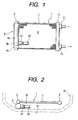
- reference numeral 1 designates a condenser.
- the condenser 1 includes a pair of left and right header pipes 3, and cooling tubes 7 with fins which are connected and communicated with one another in multisteps in a vertical direction bridging both the header pipes 3 to constitute a cooling core 5.
- One of the header pipes 3 of the condenser 1 is provided with a liquid tank 9, and the other header pipe 3 is provided with an inlet 11 and an outlet 13 for a cooling medium.
- the condenser 1 is installed at a foremost position in a front part of an engine room 15 in such a manner that a front face 19 of the condenser 1 is exposed at a front face of the engine room to which a front grille 17 is attached.
- the condenser 1 is adapted to cool a cooling medium in a gas phase having high temperature and high pressure which is introduced from a compressor located outside the drawings into the header pipes 3 through the cooling medium inlet 11, thereby to condense and liquidize the cooling medium.
- the condensed and liquidized cooling medium in a liquid phase is collected in one of the header pipes 3, and then stored in the liquid tank 9.
- liquid tank 9 In the liquid tank 9 are incorporated a drying agent for absorbing water in the cooling medium in the liquid phase, and a filter for removing small foreign substances contained therein, both of which are not shown in the drawings.
- the liquid tank 9 is in a form of a cylinder vertically elongated and having a diameter larger than that of the header pipe 3.
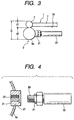
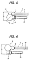
- the liquid tank 9 is attached to a front face (at a lower side in Fig. 2) of the one header pipe 3, and an auxiliary machinery part such as a pressure switch 23 is attached to a lower side of a peripheral wall face 9a of the liquid tank 9 by way of a connecting block 21.
- the liquid tank 9 is made up of a cylindrical body 9b and a lid 9c fixedly or removably attached to the cylindrical body 9b, and the cylindrical body 9b and the lid 9c define the peripheral wall face 9a of the liquid tank 9.
- the auxiliary machinery part may be attached to a part of the peripheral wall face 9a of the liquid tank 9 which is defined by the cylindrical body 9b of the liquid tank 9 or to a part of the peripheral wall face 9a of the liquid tank 9 which is defined by the lid 9c of the liquid tank 9.
- Function of the pressure switch 23 is to detect pressure of the cooling medium in the liquid phase in the refrigeration cycle and to turn on or off an electromagnetic switch for actuating the compressor outside the drawings according to a detected signal by way of a signal cable, or to control adjustment of capacity of the compressor.
- the pressure switch 23 is mounted widthwise (in a lateral direction in Fig. 3) in proximity to the front face 19 of the condenser 1, and accommodated within the diameter of the liquid tank 9.
- an overall thickness D of the condenser 1 can be set within, a size consisting of a thickness d1 of a main body of the condenser 1 plus the diameter d2 of the liquid tank 9, and therefore, the condenser 1 can be designed to be small in a direction of the thickness D.
- the liquid tank 9 may be disposed at a position which is displaced outward from the front face at a determined angle ⁇ with respect to the header pipe 3 as shown in Fig. 5, depending on a relative mounting space according to a type of the vehicle.
- liquid tank 9 may be fitted just to the side of the header pipe 3 on a same axis as shown in Fig. 6.
- the connecting block 21 of such a type that a fitting portion for fitting the pressure switch 23 is provided on its inner side face (on the right hand in the drawing) is employed, and bonded to the front face (a lower side in the drawing) of the liquid tank 9 by brazing.
- This arrangement enables the pressure switch 23 to be mounted in proximity to the front face 19 of the condenser 1 by fitting the pressure switch 23 to the fitting portion of the connecting block 21.
- the overall thickness D can be made small.
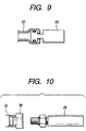
- the connecting block 21 for fitting the pressure switch 23 has a female screw thread 25 which serves as a portion to be fitted in an interior thereof, as shown in Fig. 4.
- the connecting block 21 is inserted into a mount hole 27 which is formed in a peripheral wall 9a of the liquid tank 9 and integrally fixed by blazing around the inserted area.
- the female screw thread 25 of the connecting block 21 is screw-threadedly engaged with a male screw thread 29 formed at a distal end of the pressure switch 23, and the engaged area is kept in a sealed condition by means of a sealing member 31 such as an O-ring.
- the connecting block 21 may be composed of an outer cylindrical portion 33, and an integral inner cylindrical portion 35 which is bent into the interior form the outer cylindrical portion 33.
- An arcuate outer peripheral face of the outer cylindrical portion 33 is abutted against the peripheral wall face 9a of the liquid tank 9, and the abutted faces are integrally blazed.
- a distal end of the inner cylindrical portion 35 may be inserted into the liquid tank 9, and the female screw thread 25 to be engaged with the male screw thread 29 of the pressure switch 23 may be provided on an inner face of the inner cylindrical portion 35.
- the pressure switch 23 can be fitted to the peripheral wall face 9a of the liquid tank 9 from a forward side of the front part of the engine room 15. Accordingly, the mounting work can be conducted easily and the capacity of the liquid tank 9 will not be decreased. Moreover, mounting allowability will be increased because of the larger mounting space.
- the pressure switch 23 is arranged in proximity to the front face 19 of the condenser 1 within the diameter of the liquid tank 9, the overall thickness D can be thin without decreasing the heat radiation area of the condenser 1. As the results, allowability of the installation space will be increased, and the condenser 1 can be provided at a position where the mounting work can be conducted easily.
- the cooling medium in the gas phase introduced from the cooling medium inlet 11 is cooled while passing the cooling tubes 7 and condensed to be liquidized. While the cooling medium in the liquid phase which has been condensed and liquidized passes through the liquid tank 9, the water and the small foreign substances are removed, and then, the cooling medium flows toward the cooling medium outlet 13. During these movements, the pressure switch 23 conducts measurements in the cooling medium in the liquid phase in which the cooling medium is more stable than in a two-phase zone of both gas and liquid which will be a factor of an outer turbulence, and therefore, the measuring accuracy will be enhanced.
- Figs. 8 and 9 show a second embodiment in which the pressure switch 23 is fitted to the liquid tank 9 by way of a pipe 37.
- One end of the pipe 37 is brazed to the liquid tank 9 which has been fitted to an outward side face of the header pipe 3 in the backward thereof, while the other end of the pipe 37 is extended in proximity to the front face 19 of the condenser 1.
- the distal end of the pressure switch 23 is integrally fitted by caulking to an extended end of the pipe 37, as shown in Fig. 9.
- a similar effect can be expected by fixing a connecting block 39 to an end of the pipe 37 which is extended in proximity to the front face 19 of the condenser 1 and by fitting the pressure switch 23 to the connecting block 39 as shown in Fig. 10.
- the auxiliary machinery part may include a charge valve for charging the cooling medium into the cycle, or a fusible plug which will be fused to relieve a pressure in the cycle to the exterior when an ambient temperature has risen excessively for some reason.
Landscapes
- Engineering & Computer Science (AREA)
- Physics & Mathematics (AREA)
- Mechanical Engineering (AREA)
- Thermal Sciences (AREA)
- General Engineering & Computer Science (AREA)
- Air-Conditioning For Vehicles (AREA)
- Heat-Exchange Devices With Radiators And Conduit Assemblies (AREA)
Applications Claiming Priority (2)
| Application Number | Priority Date | Filing Date | Title |
|---|---|---|---|
| JP20959899 | 1999-07-23 | ||
| JP11209598A JP2001041617A (ja) | 1999-07-23 | 1999-07-23 | 凝縮器 |
Publications (2)
| Publication Number | Publication Date |
|---|---|
| EP1070612A2 true EP1070612A2 (de) | 2001-01-24 |
| EP1070612A3 EP1070612A3 (de) | 2002-08-21 |
Family
ID=16575483
Family Applications (1)
| Application Number | Title | Priority Date | Filing Date |
|---|---|---|---|
| EP00115663A Withdrawn EP1070612A3 (de) | 1999-07-23 | 2000-07-20 | Kondensator |
Country Status (3)
| Country | Link |
|---|---|
| US (1) | US6691771B1 (de) |
| EP (1) | EP1070612A3 (de) |
| JP (1) | JP2001041617A (de) |
Families Citing this family (5)
| Publication number | Priority date | Publication date | Assignee | Title |
|---|---|---|---|---|
| JP2005321151A (ja) * | 2004-05-10 | 2005-11-17 | Sanden Corp | 熱交換器 |
| JP4707462B2 (ja) * | 2005-05-31 | 2011-06-22 | カルソニックカンセイ株式会社 | 熱交換器の配管接続構造 |
| US9194631B2 (en) * | 2012-11-20 | 2015-11-24 | Calsonickansei North America, Inc. | Heat exchanger |
| DE102015210231A1 (de) * | 2015-06-03 | 2016-12-08 | Bayerische Motoren Werke Aktiengesellschaft | Wärmetauscher für ein Kühlsystem, Kühlsystem sowie Baugruppe |
| JP2019027719A (ja) * | 2017-08-01 | 2019-02-21 | 株式会社デンソー | シリンダ部品 |
Citations (2)
| Publication number | Priority date | Publication date | Assignee | Title |
|---|---|---|---|---|
| JPH09257337A (ja) | 1996-01-16 | 1997-10-03 | Calsonic Corp | 補機部品付コンデンサ |
| JPH11209598A (ja) | 1998-01-29 | 1999-08-03 | Mitsubishi Chemical Corp | 樹脂組成物 |
Family Cites Families (6)
| Publication number | Priority date | Publication date | Assignee | Title |
|---|---|---|---|---|
| US5664432A (en) | 1993-03-24 | 1997-09-09 | Tripac International, Inc. | Vehicle air conditioning condenser |
| US5415014A (en) * | 1994-03-21 | 1995-05-16 | Thermo King Corporation | Refrigerant receiver tank assembly |
| DE69626595T2 (de) | 1995-10-18 | 2003-09-18 | Calsonic Kansei Corp., Tokio/Tokyo | Verflüssiger mit einem Flüssigkeitsbehälter |
| US5901573A (en) * | 1995-11-02 | 1999-05-11 | Calsonic Corporation | Condenser structure with liquid tank |
| JP3512931B2 (ja) | 1995-12-21 | 2004-03-31 | 昭和電工株式会社 | 受液器付き凝縮器 |
| JPH1125479A (ja) * | 1997-07-01 | 1999-01-29 | Sony Corp | 受発光素子および光学ピックアップ装置 |
-
1999
- 1999-07-23 JP JP11209598A patent/JP2001041617A/ja active Pending
-
2000
- 2000-07-20 US US09/620,578 patent/US6691771B1/en not_active Expired - Fee Related
- 2000-07-20 EP EP00115663A patent/EP1070612A3/de not_active Withdrawn
Patent Citations (2)
| Publication number | Priority date | Publication date | Assignee | Title |
|---|---|---|---|---|
| JPH09257337A (ja) | 1996-01-16 | 1997-10-03 | Calsonic Corp | 補機部品付コンデンサ |
| JPH11209598A (ja) | 1998-01-29 | 1999-08-03 | Mitsubishi Chemical Corp | 樹脂組成物 |
Also Published As
| Publication number | Publication date |
|---|---|
| EP1070612A3 (de) | 2002-08-21 |
| US6691771B1 (en) | 2004-02-17 |
| JP2001041617A (ja) | 2001-02-16 |
Similar Documents
| Publication | Publication Date | Title |
|---|---|---|
| US6446464B1 (en) | Condenser module and dryer | |
| US5813249A (en) | Refrigeration cycle | |
| US8950213B2 (en) | Receiver and receiver-integrated condenser | |
| US20110146332A1 (en) | Accumulator of air conditioner | |
| JP3925158B2 (ja) | 冷媒凝縮器 | |
| US5911274A (en) | Joint portion of heat exchanger | |
| US6691771B1 (en) | Condenser | |
| US20020059806A1 (en) | Refrigeration cycle apparatus | |
| US6981389B2 (en) | Receiver and service cartridge for a condenser system | |
| US6276445B1 (en) | Heat exchanger with heat insulating member disposed between condenser and radiator tanks | |
| EP1209426B1 (de) | Entspannungsventil | |
| JP2002213842A (ja) | 膨張弁に対する二重管の接続構造及び膨張弁 | |
| JP4513241B2 (ja) | 減圧装置 | |
| EP1319908B1 (de) | Wärmetauscher | |
| KR100421079B1 (ko) | 보조부품을구비한응축기(condenserprovidedwithauxiliarypart)및 그에 보조부품 을부착하기위한커넥터 | |
| US5768911A (en) | Refrigerating compressor oil cooling probe device | |
| JP5746872B2 (ja) | コンデンサ | |
| EP1016557B1 (de) | Kondensator für Klimaanlage für Fahrzeuge mit integrierter Expansionsvorrichtung | |
| JP4719555B2 (ja) | 熱交換器 | |
| JP2009156526A (ja) | 冷凍サイクル装置のフィルタの収納構造 | |
| JPH09196513A (ja) | レシーバドライヤ一体型コンデンサ | |
| JP2004045012A (ja) | 冷凍サイクル装置の凝縮器 | |
| JP3840624B2 (ja) | 自動車用空調装置のコンデンサ | |
| CN222480836U (zh) | 储液干燥器以及汽车空调系统 | |
| JPH08271102A (ja) | 冷凍装置 |
Legal Events
| Date | Code | Title | Description |
|---|---|---|---|
| PUAI | Public reference made under article 153(3) epc to a published international application that has entered the european phase |
Free format text: ORIGINAL CODE: 0009012 |
|
| AK | Designated contracting states |
Kind code of ref document: A2 Designated state(s): AT BE CH CY DE DK ES FI FR GB GR IE IT LI LU MC NL PT SE |
|
| AX | Request for extension of the european patent |
Free format text: AL;LT;LV;MK;RO;SI |
|
| PUAL | Search report despatched |
Free format text: ORIGINAL CODE: 0009013 |
|
| AK | Designated contracting states |
Kind code of ref document: A3 Designated state(s): AT BE CH CY DE DK ES FI FR GB GR IE IT LI LU MC NL PT SE |
|
| AX | Request for extension of the european patent |
Free format text: AL;LT;LV;MK;RO;SI |
|
| 17P | Request for examination filed |
Effective date: 20021023 |
|
| 17Q | First examination report despatched |
Effective date: 20030206 |
|
| AKX | Designation fees paid |
Designated state(s): DE FR GB |
|
| STAA | Information on the status of an ep patent application or granted ep patent |
Free format text: STATUS: THE APPLICATION IS DEEMED TO BE WITHDRAWN |
|
| 18D | Application deemed to be withdrawn |
Effective date: 20041228 |