EP1073259A2 - Geräuschdetektor, Geräuschdetektiosverfahren, Signalverarbeiter und Signalverarbeitungsverfahren - Google Patents
Geräuschdetektor, Geräuschdetektiosverfahren, Signalverarbeiter und Signalverarbeitungsverfahren Download PDFInfo
- Publication number
- EP1073259A2 EP1073259A2 EP00306457A EP00306457A EP1073259A2 EP 1073259 A2 EP1073259 A2 EP 1073259A2 EP 00306457 A EP00306457 A EP 00306457A EP 00306457 A EP00306457 A EP 00306457A EP 1073259 A2 EP1073259 A2 EP 1073259A2
- Authority
- EP
- European Patent Office
- Prior art keywords
- signal
- circuit
- level
- amplitude
- noise
- Prior art date
- Legal status (The legal status is an assumption and is not a legal conclusion. Google has not performed a legal analysis and makes no representation as to the accuracy of the status listed.)
- Granted
Links
Images

Classifications
-
- H—ELECTRICITY
- H04—ELECTRIC COMMUNICATION TECHNIQUE
- H04N—PICTORIAL COMMUNICATION, e.g. TELEVISION
- H04N5/00—Details of television systems
- H04N5/76—Television signal recording
- H04N5/91—Television signal processing therefor
- H04N5/911—Television signal processing therefor for the suppression of noise
-
- H—ELECTRICITY
- H04—ELECTRIC COMMUNICATION TECHNIQUE
- H04N—PICTORIAL COMMUNICATION, e.g. TELEVISION
- H04N1/00—Scanning, transmission or reproduction of documents or the like, e.g. facsimile transmission; Details thereof
- H04N1/40—Picture signal circuits
- H04N1/409—Edge or detail enhancement; Noise or error suppression
-
- G—PHYSICS
- G06—COMPUTING OR CALCULATING; COUNTING
- G06T—IMAGE DATA PROCESSING OR GENERATION, IN GENERAL
- G06T5/00—Image enhancement or restoration
- G06T5/70—Denoising; Smoothing
-
- G—PHYSICS
- G06—COMPUTING OR CALCULATING; COUNTING
- G06T—IMAGE DATA PROCESSING OR GENERATION, IN GENERAL
- G06T2207/00—Indexing scheme for image analysis or image enhancement
- G06T2207/20—Special algorithmic details
- G06T2207/20172—Image enhancement details
- G06T2207/20192—Edge enhancement; Edge preservation
Definitions
- the present invention relates to a noise detector and a noise detection method for detecting noise of an image signal as well as a signal processor and a signal processing method employing the noise detector and the noise detection method.
- Japanese Patent Laying-Open No. 7-307942 discloses a conventional signal processor eliminating noise from an image signal.
- Fig. 5 is a block diagram showing the structure of the conventional signal processor.
- the signal processor shown in Fig. 5 comprises a vertical adaptive filter 8 and a horizontal adaptive filter 9.
- the vertical adaptive filter 8 includes a vertical logical filter 41, a vertical unevenness determination part 42 and a selector 43.
- the horizontal adaptive filter 9 includes a horizontal logical filter 44, a horizontal unevenness determination part 45 and a selector 46.
- the vertical unevenness determination part 42 determines the magnitude of vertical unevenness around each pixel and outputs the result of the determination to the selector 43.
- the selector 43 outputs a signal of the pixel to the horizontal adaptive filter 9 as such.
- the selector 43 outputs the image signal from which vertical noise is eliminated by the vertical logical filter 41 to the horizontal adaptive filter 9.
- the horizontal unevenness determination part 45 determines the magnitude of horizontal unevenness around each pixel and outputs the result of the determination to the selector 46.
- the selector 46 outputs the image signal output from the vertical adaptive filter 8 as such.
- the selector 46 outputs the image signal from which horizontal noise is eliminated by the horizontal logical filter 44.
- the signal processor shown in Fig. 5 can eliminate noise from segments or edges included in the image signal without deteriorating the resolution, i.e., without blurring the segments or edges.
- the vertical and horizontal logical filters 41 and 44 disadvantageously blur portions continuously exhibiting fine details, such as the surfaces of clothes, the skin of a human being and a wood, for example, specific to the image signal and reduce the texture thereof.
- An object of the present invention is to provide a signal processor and a signal processing method capable of properly correcting an image signal without reducing the texture specific to the image signal also in a portion continuously exhibiting fine details.
- Another object of the present invention is to provide a noise detector and a noise detection method, employed for the aforementioned signal processor and signal processing method, capable of detecting mosquito noise and ringing of an image signal.
- the noise detector extracts the high-frequency component of the image signal and detects the level thereof, whereby the small-amplitude edge around the large-amplitude edge of the image signal can be detected on the basis of the detected level and this portion can be detected as noise. Consequently, mosquito noise and ringing caused around the large-amplitude edge of the image signal can be detected.
- the noise detection circuit may include an extension circuit outputting an extended signal obtained by extending the peak of the level signal detected by the level detection circuit, a conversion circuit outputting a 1/n signal obtained by converting the level of the extended signal output from the extension circuit to 1/n times and a small-amplitude detection circuit comparing the 1/n signal output from the conversion circuit with the level signal output from the level detection circuit for detecting the small-amplitude edge around the large-amplitude edge of the image signal.
- the small-amplitude edge existing around the large-amplitude edge corresponding to the peak of the level signal, smaller than 1/n of the level of the large-amplitude edge can be detected by comparing the 1/n signal obtained by extending the peak of the level signal and compressing the same to 1/n times with the level signal, and the small-amplitude edge can be detected as mosquito noise and ringing.
- the noise detection circuit may further include a large-amplitude detection circuit comparing the extended signal output from the extension circuit with a prescribed reference value for detecting a large-amplitude edge having a greater level than the reference value, for detecting the small-amplitude edge detected by the small-amplitude detection circuit as noise with respect to the large-amplitude edge detected by the large-amplitude detection circuit.
- the large-amplitude edge which is a signal specific to the image signal having a greater level than the reference value can be detected by comparing the extended signal obtained by extending the peak of the level signal corresponding to the large-amplitude edge with the prescribed reference value. Therefore, a small-amplitude edge around the large-amplitude edge, which is a signal specific to the image signal, can be detected as noise, and mosquito noise and ringing can be more correctly detected.
- the small-amplitude detection circuit may output a first detection result signal indicating that the 1/n signal output from the conversion circuit is greater than the level signal output from the level detection circuit
- the large-amplitude detection circuit may output a second detection result signal indicating that the extended signal output from the extension circuit is greater than the reference value
- the noise detection circuit may further include a logic circuit ANDing the first detection result signal output from the small-amplitude detection circuit and the second detection result signal output from the large-amplitude detection circuit.
- the first detection result signal indicates a portion where the 1/n signal is greater than the level signal, i.e., a portion excluding a large-amplitude edge portion while the second detection result signal indicates a portion where the extended signal is greater than the reference value, i.e., a small-amplitude edge portion around the large-amplitude edge including the large-amplitude edge portion. Therefore, only the small-amplitude edge around the large-amplitude edge can be detected by ANDing the outputs. Consequently, only mosquito noise and ringing can be detected from the portion around the large-amplitude edge of the image signal with a simple structure employing a binary signal.
- the high-frequency component extraction circuit may include a horizontal extraction circuit extracting a horizontal high-frequency component of the ipput image signal, a vertical extraction circuit extracting a vertical high-frequency component of the input image signal and an adder circuit adding the horizontal high-frequency component extracted by the horizontal extraction circuit and the vertical high-frequency component extracted by the vertical extraction circuit to each other, the level detection circuit may detect the level of the sum of the high-frequency components by the adder circuit and outputting the result of detection as the level signal, and the noise detection circuit may detect horizontal and vertical small-amplitude edges around horizontal and vertical large-amplitude edges of the image signal on the basis of the level signal detected by the level detection circuit.
- the horizontal and vertical high-frequency components are extracted and added to each other, and the level of the sum of the high-frequency components is thereafter detected so that the horizontal and vertical small-amplitude edges around the horizontal and vertical large-amplitude edges of the image signal can be detected as noise on the basis of the level signal. Therefore, horizontal and vertical mosquito noise and ringing caused around the horizontal and vertical large-amplitude edges of the image signal can be detected.
- the extracted horizontal and vertical high-frequency components are added to each other for performing subsequent horizontal and vertical processing in common, whereby the structure following addition is so simplified that the horizontal and vertical mosquito noise and ringing can be detected with a simple structure.
- a signal processor comprises a detection circuit detecting horizontal and/or vertical small-amplitude edge(s) around horizontal and/or vertical large-amplitude edge(s) of an input image signal as noise and a processing circuit performing horizontal and/or vertical correction of the image signal in response to the result of detection in the detection circuit.
- the signal processor detects the horizontal and/or vertical small amplitude edge(s) around the horizontal and/or vertical large-amplitude edge(s) of the image signal as noise thereby detecting mosquito noise and ringing of the image signal and performing horizontal and/or vertical correction of the input image signal in response to the result of detection. Therefore, the image signal can be properly corrected in response to the states of mosquito noise and ringing. Consequently, the image signal can be properly corrected without reducing the texture specific to the image signal also in a portion continuously exhibiting fine details.
- the processing circuit may include a smoothing circuit performing horizontal and/or vertical smoothing of the image signal in response to noise detected by the detection circuit.
- the image signal is subjected to horizontal and/or vertical smoothing in response to the detected noise, i.e., mosquito noise and ringing, whereby proper smoothing can be performed in response to the states of the mosquito noise and the ringing.
- the detected noise i.e., mosquito noise and ringing
- the smoothing circuit preferably performs horizontal and/or vertical smoothing of the image signal when the detection circuit detects noise.
- the image signal is subjected to horizontal and/or vertical smoothing when noise, i.e., mosquito noise and ringing take place, whereby only mosquito noise and ringing can be smoothed for implementing an image having neither mosquito noise nor ringing.
- the processing circuit may include a contour correction circuit performing horizontal and/or vertical contour correction of the image signal in response to noise detected by the detection circuit.
- the image signal is subjected to horizontal and/or vertical contour correction in response to the detected noise, i.e., mosquito noise and ringing, whereby proper contour correction can be performed in response to the states of the mosquito noise and the ringing.
- the detected noise i.e., mosquito noise and ringing
- the contour correction circuit preferably performs the horizontal and/or vertical contour correction of the image signal when the detection circuit detects no noise.
- the image signal is subjected to horizontal and/or vertical contour correction when no noise, i.e., neither mosquito noise nor ringing takes place, whereby a high-quality image enhanced in an edge portion specific to the image signal can be implemented without enhancing mosquito noise and ringing.
- the detection circuit may include a high-frequency component extraction circuit extracting a high-frequency component of the input image signal, a level detection circuit detecting the level of the high-frequency component extracted by the high-frequency component extraction circuit and outputting the result of detection as a level signal and a noise detection circuit detecting the small-amplitude edge around the large-amplitude edge of the image signal on the basis of the level signal detected by the level detection circuit.
- the high-frequency component of the image signal is extracted for detecting the level thereof, whereby the small-amplitude edge around the large-amplitude edge of the image signal can be detected on the basis of the detected level and this portion can be detected as noise. Therefore, mosquito noise and ringing caused around the large-amplitude edge of the image signal can be detected.
- the noise detection circuit may include an extension circuit outputting an extended signal obtained by extending the peak of the level signal detected by the level detection circuit, a conversion circuit outputting a 1/n signal obtained by converting the level of the extended signal output from the extension circuit to 1/n times and a small-amplitude detection circuit comparing the 1/n signal output from the conversion circuit with the level signal output from the level detection circuit for detecting the small-amplitude edge around the large-amplitude edge of the image signal.
- the small-amplitude edge existing around the large-amplitude edge corresponding to the peak of the level signal, smaller than 1/n of the level of the large-amplitude edge can be detected by comparing the 1/n signal obtained by extending the peak of the level signal and compressing the same to 1/n times with the level signal, and this small-amplitude edge can be detected as mosquito noise and ringing.
- the noise detection circuit may further include a large-amplitude detection circuit comparing the extended signal output from the extension circuit with a prescribed reference value for detecting a large-amplitude edge having a greater level than the reference value, for detecting the small-amplitude edge detected by the small-amplitude detection circuit as noise with respect to the large-amplitude edge detected by the large-amplitude detection circuit.
- the large-amplitude edge which is a signal specific to the image signal having a greater level than the reference value
- the large-amplitude edge can be detected by comparing the extended signal obtained by extending the peak of the level signal corresponding to the large-amplitude edge with the prescribed reference value. Therefore, a small-amplitude edge around the large-amplitude edge, which is a signal specific to the image signal, can be detected as noise, and mosquito noise and ringing can be more correctly detected.
- the small-amplitude detection circuit may output a first detection result signal indicating that the 1/n signal output from the conversion circuit is greater than the level signal output from the level detection circuit
- the large-amplitude detection circuit may output a second detection result signal indicating that the extended signal output from the extension circuit is greater than the reference value
- the noise detection circuit may further include a logic circuit ANDing the first detection result signal output from the small-amplitude detection circuit and the second detection result signal output from the large-amplitude detection circuit.
- the first detection result signal indicates a portion where the 1/n signal is greater than the level signal, i.e., a portion excluding a large-amplitude edge portion while the second detection result signal indicates a portion where the extended signal is greater than the reference value, i.e., a small-amplitude edge portion around the large-amplitude edge including the large-amplitude edge portion. Therefore, only the small-amplitude edge around the large-amplitude edge can be detected by ANDing the outputs. Consequently, only mosquito noise and ringing can be detected from the portion around the large-amplitude edge of the image signal with a simple structure employing a binary signal.
- the high-frequency component extraction circuit may include a horizontal extraction circuit extracting a horizontal high-frequency component of the input image signal, a vertical extraction circuit extracting a vertical high-frequency component of the input image signal and an adder circuit adding the horizontal high-frequency component extracted by the horizontal extraction circuit and the vertical high-frequency component extracted by the vertical extraction circuit to each other, the level detection circuit may detect the level of the sum of the high-frequency components obtained by the adder circuit and outputting the result of detection as the level signal, and the noise detection circuit may detect horizontal and vertical small-amplitude edges around horizontal and vertical large-amplitude edges of the image signal on the basis of the level signal detected by the level detection circuit.
- the horizontal and vertical high-frequency components are extracted and added to each other, and the level of the sum of the high-frequency components is thereafter detected so that the horizontal and vertical small-amplitude edges around the horizontal and vertical large-amplitude edges of the image signal can be detected as noise on the basis of the level signal. Therefore, horizontal and vertical mosquito noise and ringing caused around the horizontal and vertical large-amplitude edges of the image signal can be detected.
- the extracted horizontal and vertical high-frequency components are added to each other for performing subsequent horizontal and vertical processing in common, whereby the structure following addition is so simplified that the horizontal and vertical mosquito noise and ringing can be detected with a simple structure.
- a noise detection method comprises steps of extracting a high-frequency component of an input image signal, detecting the level of the extracted high-frequency component and outputting the result of detection as a level signal, and detecting a small-amplitude edge around a large-amplitude edge of the image signal as noise on the basis of the level signal.
- the high-frequency component of the image signal is extracted for detecting the level thereof in the noise detection method, whereby the small-amplitude edge around the large-amplitude edge of the image signal can be detected on the basis of the detected level and this portion can be detected as noise. Consequently, mosquito noise and ringing caused around the large-amplitude edge of the image signal can be detected.
- the noise detection step may include steps of outputting an extended signal obtained by extending the peak of the level signal, outputting a 1/n signal obtained by converting the level of the extended signal to 1/n times, and comparing the 1/n signal with the level signal and detecting the small-amplitude edge around the large-amplitude edge of the image signal.
- the small-amplitude edge existing around the large-amplitude edge corresponding to the peak of the level signal, smaller than 1/n of the level of the large-amplitude edge can be detected by comparing the 1/n signal obtained by extending the peak of the level signal and compressing the same to 1/n times with the level signal, and this small-amplitude edge can be detected as mosquito noise and ringing.
- the noise detection step may further include a step of comparing the extended signal with a prescribed reference level and detecting a large-amplitude edge having a greater level than the reference value, for detecting the small-amplitude edge as noise with respect to the large-amplitude edge.
- the large-amplitude edge which is a signal specific to the image signal having a greater level than the reference value
- the large-amplitude edge can be detected by comparing the extended signal obtained by extending the peak of the level signal corresponding to the large-amplitude edge with the prescribed reference value. Therefore, a small-amplitude edge around the large-amplitude edge specific to the image signal can be detected as noise, and mosquito noise and ringing can be more correctly detected.
- a signal processing method comprises steps of detecting horizontal and/or vertical small-amplitude edge(s) around horizontal and/or vertical large-amplitude edge(s) of an input image signal as noise and performing horizontal and/or vertical correction of the image signal in response to the result of detection of the noise.
- mosquito noise and ringing of the image signal are detected by detecting the horizontal and/or vertical small-amplitude edge(s) around the horizontal and/vertical large-amplitude edge(s) of the image signal for performing horizontal and/or vertical correction of the input image signal in response to the result of detection. Therefore, the image signal can be properly corrected in response to the states of the mosquito noise and the ringing. Consequently, the image signal can be properly corrected without reducing the texture specific to the image signal also in a portion continuously exhibiting fine details.
- the step of performing correction may include a step of performing horizontal and/or vertical smoothing of the image signal when noise is detected in the noise detection step.
- the image signal is subjected to horizontal and/or vertical smoothing when noise, i.e., mosquito noise and ringing take place, whereby only the mosquito noise and the ringing can be smoothed for implementing an image having neither mosquito noise nor ringing.
- noise i.e., mosquito noise and ringing
- the step of performing correction may include a step of performing horizontal and/or vertical contour correction of the image signal when no noise is detected in the noise detection step.
- the image signal is subjected to horizontal and/or vertical contour correction when no noise, i.e., neither mosquito noise or ringing takes place, whereby a high-quality image having an enhanced edge portion specific to the image signal can be implemented without enhancing mosquito noise and ringing.
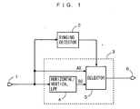
- the signal processor shown in Fig. 1 comprises a ringing detector 2 and a signal smoother 3.
- the signal smoother 3 includes a horizontal/vertical low-pass filter (LPF) 4 and a selector 5.
- LPF horizontal/vertical low-pass filter
- the ringing detector 2 detects horizontal and vertical small-amplitude edges around horizontal and vertical large-amplitude edges of an image signal input through an image signal input terminal 1 as noise, and outputs the result of detection to the selector 5.
- the noise detected by the ringing detector 2 including ringing caused when transferring a digital image and mosquito noise caused when compression-coding the digital image, corresponds to ringing components caused around the large-amplitude edges.
- the ringing detector 2 corresponds to the detection circuit
- the signal smoother 3 corresponds to the processing circuit and the smoothing circuit.
- the image signal is input through the image signal input terminal 1, so that the ringing detector 2 detects portions causing mosquito noise and ringing around the large-amplitude edges of the image signal and outputs the result of detection to the selector 5.
- the selector 5 When the ringing detector 2 detects that the image signal has a portion causing mosquito noise and ringing, on the other hand, the selector 5 outputs the signal input in the input terminal B0, i.e., the image signal smoothed by the horizontal/vertical low-pass filter 4 to the image signal output terminal 6.
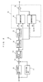
- Fig. 2 is a block diagram showing the structure of the ringing detector 2 shown in Fig. 1.
- the ringing detector 2 shown in Fig. 2 includes a horizontal high-pass filter (HPF) 10, a vertical high-pass filter (HPF) 11, an adder 12, an absolute value detector 13, a signal extender 14, a level converter 15 and a ringing determination part 19.
- the ringing determination part 19 includes comparators 16 and 17 and an AND gate 18.
- the adder 12 adds the horizontal high-frequency component extracted by the horizontal high-pass filter 10 and the vertical high-frequency component extracted by the vertical high-pass filter 11 to each other, and outputs the result to the absolute value detector 13.
- the absolute value detector 13 obtains the absolute value of the sum of the high-frequency components, and outputs the result to the signal extender 14 as a level signal.
- the signal extender 14 outputs an extended signal obtained by horizontally and vertically extending the peak of the level signal output from the absolute value detector 13 to the level converter 15.
- the level converter 15 outputs a 1/n signal obtained by converting the level of the extended signal output from the signal extender 14 to 1/n times to an input terminal A1 of the comparator 16.
- the value n is set for detecting small-amplitude edges having levels less than 1/n of the levels of the large-amplitude edges as mosquito noise and ringing.
- the value n which can be set to an arbitrary value such as an integer or a real number, is preferably set to a value of at least 2 and not more than 8, more preferably at least 4 and not more than 8.
- the value n can be arbitrarily set from outside the signal processor, or may alternatively be previously stored in the signal processor if the value n is previously decided.
- the comparator 16 compares the 1/n signal input in the input terminal A1 from the level converter 15 with the level signal input in another input terminal B1 from the absolute value detector 13 and outputs "1" (high in this embodiment) to the AND gate 18 when the 1/n signal is greater than the level signal while otherwise outputting "0" (low in this embodiment) to the AND gate 18.
- the comparator 17 compares the extended signal input in an input terminal A2 from the signal extender 14 with a reference value SL input in another input terminal B2, for outputting "1" to the AND gate 18 when the extended signal is greater than the reference value SL, while otherwise outputting "0" to the AND gate 18.
- the reference value SL is employed for detecting a signal specific to the image signal from the large-amplitude edges of the image signal. While an arbitrary value such as an integer or a real number can be employed as the reference value SL, a value of at least 64 is preferably employed when employing data of eight bits, i.e., 256 gradations as the maximum level of the image signal, for example.
- the reference value SL may be arbitrarily set from outside the signal processor, or may alternatively be previously stored in the signal processor when the value thereof is previously decided.
- the comparator 17 may alternatively compare the 1/n signal output from the level converter 15 with the reference value SL, which is also set to 1/n times in this case.
- the AND gate 18 is connected to the selector 5 shown in Fig. 1, for outputting a signal of "1" to the selector 5 when both of the output signals from the comparators 16 and 17 are “1", while otherwise outputting a signal of "0" to the selector 5.
- the horizontal high-pass filter 10, the vertical high-pass filter 11 and the adder 12 correspond to the high-frequency component extraction circuit
- the absolute value detector 13 corresponds to the level detection circuit
- the signal extender 14 corresponds to the extension circuit
- the level converter 15 corresponds to the conversion circuit
- the comparator 16 corresponds to the small-amplitude detection circuit
- the comparator 17 corresponds to the large-amplitude detection circuit
- the AND gate 18 corresponds to the logic circuit.
- the horizontal high-pass filter 10 corresponds to the horizontal extraction circuit
- the vertical high-pass filter 11 corresponds to the vertical extension circuit
- the adder 12 corresponds to the adder circuit.
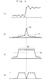
- Fig. 3 is a waveform diagram for illustrating the operations of the ringing detector shown in Fig. 2. Only horizontal processing of the ringing detector is hereafter described for simplifying the illustration. Vertical processing of the ringing detector is substantially similar to the horizontal processing described below except that delay processing is different due to different delay times for the processed signal and a memory corresponding thereto is employed, and hence redundant description is not repeated.
- the horizontal and vertical high-pass filters 10 and 11 extract horizontal and vertical high-frequency components from the image signal respectively, and the adder 12 adds the extracted high-frequency components to each other.
- the absolute value detector 13 obtains the absolute value of the sum of the high-frequency components and outputs a level signal having a peak point P1 corresponding to a large-amplitude edge shown at (1) in Fig. 3, as shown by a solid line at (2) in Fig. 3.
- the level converter 15 outputs a 1/n signal obtained by converting the extended signal shown by the solid line at (3) in Fig. 3 to 1/n times, as shown by a broken line at (2) in Fig. 3.
- the comparator 16 compares the 1/n signal shown by the broken line at (2) in Fig. 3 with the level signal shown by the solid line, for outputting a result signal of "1" to the AND gate 18 when the 1/n signal is greater than the level signal, while otherwise outputting a result signal of "0" to the AND gate 18.
- the 1/n signal is greater than the level signal except the peak point P1, and hence the part other than the peak point P1 is output as "1" while the part of the peak point P1 is output as "0".
- the comparator 17 compares the extended signal shown by the solid line at (3) in Fig. 3 with the reference value SL shown by a broken line, for outputting a result signal of "1" to the AND gate 18 when the extended signal is greater than the reference value SL, while otherwise outputting a result signal of "0" to the AND gate 18.
- the extended signal is greater than the reference value SL in a peak part P2 corresponding the central pixel, the four pixels on the right and the four pixels on the left, i.e., nine pixels in total, and hence the peak part P2 is output as "1" while the remaining part is output as "0".
- the AND gate 18 ANDs the result signals output from the comparators 16 and 17, and outputs a signal shown at (4) in Fig. 3 to the selector 5 shown in Fig. 1.
- the part corresponding to the peak point P1 is output as "0”
- the parts corresponding to the four pixels on the right and the four pixels on the left are output as "1”
- the remaining parts on both sides of these parts are output as "0".
- the comparator 16 compares the level of the small-amplitude edge around the large-amplitude edge with the level of the large-amplitude edge converted to 1/n times and the comparator 17 compares the level of the large-amplitude edge with the reference value SL, thereby detecting the small-amplitude edge around the large-amplitude edge as noise only when the large-amplitude edge has a level greater than that of the reference value SL and the level of the small-amplitude edge around the same is less than the level of the large-amplitude edge converted to 1/n times. Consequently, only mosquito noise and ringing can be correctly detected independently of parts specific to the image signal.
- the ringing detector 2 shown in Fig. 2 performing vertical processing similarly to the above, can detect vertical and horizontal small-amplitude edges around vertical and horizontal large-amplitude edges of the image signal as noise, for detecting horizontal and vertical mosquito noise and ringing around the horizontal and vertical large-amplitude edges of the image signal.
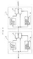
- FIG. 4 is a block diagram showing the structure of the signal processor according to the second embodiment of the present invention.
- the signal processor shown in Fig. 4 comprises a ringing detector 2 and a contour corrector 7.
- the contour corrector 7 includes a horizontal/vertical high-pass filter (HPF) 22, an adder 23 and a selector 24.
- HPF horizontal/vertical high-pass filter
- the ringing detector 2 shown in Fig. 4 is similar to that shown in Fig. 2, and hence redundant description is not repeated.
- the horizontal/vertical high-pass filter 22 extracts horizontal and vertical high-frequency components from an image signal input through an image signal input terminal 1, and outputs the extracted high-frequency components to the adder 23.
- the adder 23 adds the horizontal and vertical high-frequency components output from the horizontal/vertical high-pass filter 22 and the image signal input through the image signal input terminal 1 to each other, and outputs a contour-corrected image signal to an input terminal A3 of the selector 24.
- Another input terminal B3 of the selector 24 receives the image signal as such through the image signal input terminal 1.
- the selector 24 selects either the contour-corrected image signal input from the input terminal A3 or the image signal input from the input terminal B3 in response to a noise detection result output from the ringing detector 2 and outputs the selected signal to an image signal output terminal 6.
- the ringing detector 2 corresponds to the noise detection circuit
- the contour corrector 7 corresponds to the processing circuit and the contour correction circuit.
- the image signal is input through the image signal input terminal 1, and the ringing detector 2 detects portions causing mosquito noise and ringing around large-amplitude edges of the input image signal and outputs the result of detection to the selector 24.
- the selector 24 When the ringing detector 2 detects portions causing neither mosquito noise nor ringing, the selector 24 outputs the signal input in the input terminal A3, i.e., the image signal subjected to contour correction by the horizontal/vertical high-pass filter 22 and the adder 23 to the image signal output terminal 6.
- the selector 24 When the ringing detector 2 detects portions causing mosquito noise and ringing, the selector 24 outputs the image signal input from the image signal input terminal 1 in the input terminal B3 to the image signal output terminal 6 as such. In this case, therefore, no contour correction is performed but the image signal is output as such.
- the ringing detector 2 may alternatively detect the levels of the mosquito noise and the ringing for deciding whether or not to perform smoothing or contour correction in response to the levels of the mosquito noise and the ringing or changing the degree of the smoothing or the contour correction in response to the levels of the mosquito noise and the ringing.
- the present invention is also applicable to the case of only horizontally or vertically processing the image signal.
- ringing detector 2 and the signal processor are formed by hardware in each of the aforementioned embodiments, the processing of the aforementioned parts may alternatively be performed through software with a DSP (digital signal processor) or the like, to attain effects similar to the above.
- DSP digital signal processor
Landscapes
- Engineering & Computer Science (AREA)
- Multimedia (AREA)
- Signal Processing (AREA)
- Physics & Mathematics (AREA)
- General Physics & Mathematics (AREA)
- Theoretical Computer Science (AREA)
- Picture Signal Circuits (AREA)
- Image Processing (AREA)
- Studio Circuits (AREA)
- Noise Elimination (AREA)
Applications Claiming Priority (2)
| Application Number | Priority Date | Filing Date | Title |
|---|---|---|---|
| JP11215000A JP2001045336A (ja) | 1999-07-29 | 1999-07-29 | ノイズ検出装置、ノイズ検出方法、信号処理装置および信号処理方法 |
| JP21500099 | 1999-07-29 |
Publications (3)
| Publication Number | Publication Date |
|---|---|
| EP1073259A2 true EP1073259A2 (de) | 2001-01-31 |
| EP1073259A3 EP1073259A3 (de) | 2003-10-01 |
| EP1073259B1 EP1073259B1 (de) | 2005-06-22 |
Family
ID=16665053
Family Applications (1)
| Application Number | Title | Priority Date | Filing Date |
|---|---|---|---|
| EP00306457A Expired - Lifetime EP1073259B1 (de) | 1999-07-29 | 2000-07-28 | Rauschdetektor und Rauschdetektionsverfahren |
Country Status (7)
| Country | Link |
|---|---|
| US (1) | US6795588B1 (de) |
| EP (1) | EP1073259B1 (de) |
| JP (1) | JP2001045336A (de) |
| KR (1) | KR100679789B1 (de) |
| CN (1) | CN1187961C (de) |
| DE (1) | DE60020910T2 (de) |
| SG (1) | SG93250A1 (de) |
Cited By (1)
| Publication number | Priority date | Publication date | Assignee | Title |
|---|---|---|---|---|
| EP2052350A4 (de) * | 2006-07-19 | 2011-08-03 | Trident Microsystems Inc | Verfahren und system zur verringerung von moskitorauschen in einem digitalbild |
Families Citing this family (24)
| Publication number | Priority date | Publication date | Assignee | Title |
|---|---|---|---|---|
| KR20020068079A (ko) * | 2000-11-13 | 2002-08-24 | 코닌클리케 필립스 일렉트로닉스 엔.브이. | 비대칭 과도 신호들의 검출 및 보정 |
| FR2818863A1 (fr) * | 2000-12-26 | 2002-06-28 | Koninkl Philips Electronics Nv | Procede de traitement de donnees |
| JP3734430B2 (ja) * | 2001-05-09 | 2006-01-11 | 三菱電機株式会社 | 輪郭補正回路 |
| FR2841423A1 (fr) * | 2002-06-25 | 2003-12-26 | Koninkl Philips Electronics Nv | Procede de detection d'artefacts de bloc |
| CN100505525C (zh) * | 2002-11-01 | 2009-06-24 | 松下电器产业株式会社 | 滤波电路 |
| WO2004040755A1 (ja) * | 2002-11-01 | 2004-05-13 | Matsushita Electric Industrial Co., Ltd. | フィルタ回路及び無線装置 |
| ATE474393T1 (de) * | 2003-05-21 | 2010-07-15 | Koninkl Philips Electronics Nv | Verfahren und vorrichtung zur authentifikation eines physischen gegenstandes |
| US7339601B2 (en) * | 2003-07-10 | 2008-03-04 | Samsung Electronics Co., Ltd. | Methods of suppressing ringing artifact of decompressed images |
| JP4072491B2 (ja) * | 2003-10-23 | 2008-04-09 | キヤノン株式会社 | 画像処理装置、画像処理方法、プログラム及びコンピュータ可読媒体 |
| JP2005167399A (ja) * | 2003-11-28 | 2005-06-23 | Noritsu Koki Co Ltd | 画像ノイズ除去方法 |
| US7570831B2 (en) * | 2004-04-29 | 2009-08-04 | Hewlett-Packard Development Company, L.P. | System and method for estimating image noise |
| JP4129254B2 (ja) * | 2004-08-03 | 2008-08-06 | 富士フイルム株式会社 | ノイズ低減装置および方法 |
| JP2006050358A (ja) * | 2004-08-06 | 2006-02-16 | Pioneer Electronic Corp | 映像信号処理装置 |
| JP4457346B2 (ja) * | 2004-11-12 | 2010-04-28 | ノーリツ鋼機株式会社 | 画像ノイズ除去方法 |
| US7136536B2 (en) * | 2004-12-22 | 2006-11-14 | Telefonaktiebolaget L M Ericsson (Publ) | Adaptive filter |
| JP2006340005A (ja) | 2005-06-01 | 2006-12-14 | Sony Corp | ディジタル信号処理装置とディジタル信号処理方法およびプログラム。 |
| US7548660B2 (en) * | 2005-09-30 | 2009-06-16 | Intel Corporation | System and method of spatio-temporal edge-preserved filtering techniques to reduce ringing and mosquito noise of digital pictures |
| JP4135953B2 (ja) * | 2005-12-05 | 2008-08-20 | インターナショナル・ビジネス・マシーンズ・コーポレーション | 波形測定装置及びその測定方法 |
| US8115967B2 (en) * | 2006-11-28 | 2012-02-14 | Silverbrook Research Pty Ltd | Localized signal data preservation within signal bandwidth |
| DE102011106647A1 (de) * | 2011-07-05 | 2013-01-10 | J. Eberspächer GmbH & Co. KG | Antischall-system für abgasanlagen und verfahren zum steuern desselben |
| US10010898B2 (en) | 2013-03-15 | 2018-07-03 | S. C. Johnson & Son, Inc. | Dispensing systems with wave sensors |
| KR102211592B1 (ko) * | 2014-03-19 | 2021-02-04 | 삼성전자주식회사 | 전자 장치 및 이의 영상 처리 방법 |
| CN105588609A (zh) * | 2016-02-24 | 2016-05-18 | 叶志刚 | 一种用于侦测蚊子的装置 |
| KR102704879B1 (ko) | 2022-10-06 | 2024-09-09 | 주식회사 라우드에이아이 | 센싱신호로부터 노이즈를 제거하기 위한 장치 및 노이즈 제거하기 위한 방법 |
Family Cites Families (16)
| Publication number | Priority date | Publication date | Assignee | Title |
|---|---|---|---|---|
| JP2801213B2 (ja) * | 1988-08-22 | 1998-09-21 | 日本電信電話株式会社 | 画像雑音除去処理方法 |
| JPH0767176B2 (ja) * | 1990-11-28 | 1995-07-19 | 松下電器産業株式会社 | 符号化雑音除去フィルタ |
| DE69230548T2 (de) * | 1991-08-23 | 2000-06-15 | Mitsubishi Denki K.K., Tokio/Tokyo | Pixelinterpolationsschaltkreis und Anwendungen |
| JPH05328121A (ja) * | 1992-05-20 | 1993-12-10 | Ricoh Co Ltd | 画像処理方法およびその装置 |
| JP2673778B2 (ja) * | 1994-02-22 | 1997-11-05 | 国際電信電話株式会社 | 動画像の復号化における雑音低減装置 |
| JPH07307942A (ja) | 1994-05-13 | 1995-11-21 | Hitachi Ltd | 画像雑音除去装置 |
| US5754699A (en) * | 1994-11-24 | 1998-05-19 | Victor Company Of Japan, Ltd. | Method of reducing mosquito noise generated during decoding process of image data and device for decoding image data using the same |
| JPH08163594A (ja) * | 1994-12-12 | 1996-06-21 | Sony Corp | 動画像復号化方法及び動画像復号化装置 |
| EP0721286A3 (de) * | 1995-01-09 | 2000-07-26 | Matsushita Electric Industrial Co., Ltd. | Einrichtung zur Dekodierung von Videosignalen mit Verminderung von Artefakten |
| US5852475A (en) | 1995-06-06 | 1998-12-22 | Compression Labs, Inc. | Transform artifact reduction process |
| JP3221291B2 (ja) * | 1995-07-26 | 2001-10-22 | ソニー株式会社 | 画像処理装置、画像処理方法、ノイズ除去装置及びノイズ除去方法 |
| US5819035A (en) * | 1995-10-20 | 1998-10-06 | Matsushita Electric Industrial Co., Ltd. | Post-filter for removing ringing artifacts of DCT coding |
| JPH10191326A (ja) * | 1996-11-08 | 1998-07-21 | Sony Corp | 画像処理装置および方法 |
| US6148115A (en) * | 1996-11-08 | 2000-11-14 | Sony Corporation | Image processing apparatus and image processing method |
| US6088065A (en) * | 1997-09-03 | 2000-07-11 | Victor Company Of Japan, Ltd. | Contour correction apparatus and method |
| JP3863294B2 (ja) * | 1998-07-02 | 2006-12-27 | 株式会社日立製作所 | ノイズ低減信号処理回路および映像表示装置 |
-
1999
- 1999-07-29 JP JP11215000A patent/JP2001045336A/ja active Pending
-
2000
- 2000-07-24 SG SG200004131A patent/SG93250A1/en unknown
- 2000-07-28 US US09/628,678 patent/US6795588B1/en not_active Expired - Fee Related
- 2000-07-28 KR KR1020000043608A patent/KR100679789B1/ko not_active Expired - Fee Related
- 2000-07-28 DE DE2000620910 patent/DE60020910T2/de not_active Expired - Lifetime
- 2000-07-28 EP EP00306457A patent/EP1073259B1/de not_active Expired - Lifetime
- 2000-07-31 CN CNB001224654A patent/CN1187961C/zh not_active Expired - Fee Related
Cited By (1)
| Publication number | Priority date | Publication date | Assignee | Title |
|---|---|---|---|---|
| EP2052350A4 (de) * | 2006-07-19 | 2011-08-03 | Trident Microsystems Inc | Verfahren und system zur verringerung von moskitorauschen in einem digitalbild |
Also Published As
| Publication number | Publication date |
|---|---|
| DE60020910T2 (de) | 2006-04-27 |
| KR100679789B1 (ko) | 2007-02-07 |
| JP2001045336A (ja) | 2001-02-16 |
| SG93250A1 (en) | 2002-12-17 |
| EP1073259A3 (de) | 2003-10-01 |
| DE60020910D1 (de) | 2005-07-28 |
| CN1187961C (zh) | 2005-02-02 |
| US6795588B1 (en) | 2004-09-21 |
| EP1073259B1 (de) | 2005-06-22 |
| CN1283036A (zh) | 2001-02-07 |
| KR20010015457A (ko) | 2001-02-26 |
Similar Documents
| Publication | Publication Date | Title |
|---|---|---|
| US6795588B1 (en) | Noise detector, noise detection method, signal processor and signal processing method | |
| JP2871127B2 (ja) | 画像処理装置及び方法 | |
| KR100687645B1 (ko) | 움직임 검출 장치 및 그것을 이용한 잡음 제거 장치 | |
| GB2247377A (en) | Motion signal processor. | |
| JP4169188B2 (ja) | 画像処理方法 | |
| US6999130B2 (en) | Luminance signal/chrominance signal separation device, and luminance signal/chrominance signal separation method | |
| EP1285407A2 (de) | Randdetektionsverfahren und -vorrichtung | |
| KR100281877B1 (ko) | 임펄스노이즈감소장치및그방법 | |
| JPH08163408A (ja) | ノイズ検出回路、ノイズ除去回路及び輪郭強調回路 | |
| US5635990A (en) | Apparatus for cancelling noise and improving details of images | |
| JP3314043B2 (ja) | 動き検出回路とノイズ低減装置 | |
| JPH1132236A (ja) | 画像処理装置 | |
| KR20020093076A (ko) | 화상 노이즈 저감 방법 및 장치 | |
| JPH1117954A (ja) | 映像信号処理装置 | |
| US6781625B2 (en) | Noise reducing apparatus | |
| US7400775B2 (en) | Edge enhancement system and method and imaging system | |
| JPH0981754A (ja) | 動き検出回路 | |
| JPH08102873A (ja) | フィルタ構造及びろ波方法 | |
| JPH0856316A (ja) | 画像処理装置 | |
| US7639287B2 (en) | Video imaging apparatus having non-linear input-output characteristic for improved image contrast control | |
| JP4832411B2 (ja) | ノイズ低減処理装置及びノイズ低減処理方法 | |
| JP3014102B2 (ja) | 輪郭補正回路 | |
| JPH07111605A (ja) | 雑音除去回路 | |
| JP3355656B2 (ja) | ディジタル画像信号からのエッジ抽出装置および方法 | |
| JP4019503B2 (ja) | 映像信号処理装置及び映像信号処理方法 |
Legal Events
| Date | Code | Title | Description |
|---|---|---|---|
| PUAI | Public reference made under article 153(3) epc to a published international application that has entered the european phase |
Free format text: ORIGINAL CODE: 0009012 |
|
| AK | Designated contracting states |
Kind code of ref document: A2 Designated state(s): AT BE CH CY DE DK ES FI FR GB GR IE IT LI LU MC NL PT SE |
|
| AX | Request for extension of the european patent |
Free format text: AL;LT;LV;MK;RO;SI |
|
| PUAL | Search report despatched |
Free format text: ORIGINAL CODE: 0009013 |
|
| AK | Designated contracting states |
Kind code of ref document: A3 Designated state(s): AT BE CH CY DE DK ES FI FR GB GR IE IT LI LU MC NL PT SE |
|
| AX | Request for extension of the european patent |
Extension state: AL LT LV MK RO SI |
|
| RIC1 | Information provided on ipc code assigned before grant |
Ipc: 7G 06T 5/00 B Ipc: 7H 04N 7/26 A Ipc: 7H 04N 1/409 B |
|
| 17P | Request for examination filed |
Effective date: 20040330 |
|
| 17Q | First examination report despatched |
Effective date: 20040428 |
|
| AKX | Designation fees paid |
Designated state(s): DE FR GB |
|
| RTI1 | Title (correction) |
Free format text: NOISE DETECTOR AND NOISE DETECTION METHOD |
|
| GRAP | Despatch of communication of intention to grant a patent |
Free format text: ORIGINAL CODE: EPIDOSNIGR1 |
|
| GRAS | Grant fee paid |
Free format text: ORIGINAL CODE: EPIDOSNIGR3 |
|
| GRAA | (expected) grant |
Free format text: ORIGINAL CODE: 0009210 |
|
| AK | Designated contracting states |
Kind code of ref document: B1 Designated state(s): DE FR GB |
|
| REG | Reference to a national code |
Ref country code: GB Ref legal event code: FG4D |
|
| REF | Corresponds to: |
Ref document number: 60020910 Country of ref document: DE Date of ref document: 20050728 Kind code of ref document: P |
|
| ET | Fr: translation filed | ||
| PLBE | No opposition filed within time limit |
Free format text: ORIGINAL CODE: 0009261 |
|
| STAA | Information on the status of an ep patent application or granted ep patent |
Free format text: STATUS: NO OPPOSITION FILED WITHIN TIME LIMIT |
|
| 26N | No opposition filed |
Effective date: 20060323 |
|
| REG | Reference to a national code |
Ref country code: GB Ref legal event code: 746 Effective date: 20100127 |
|
| REG | Reference to a national code |
Ref country code: FR Ref legal event code: PLFP Year of fee payment: 16 |
|
| PGFP | Annual fee paid to national office [announced via postgrant information from national office to epo] |
Ref country code: DE Payment date: 20150722 Year of fee payment: 16 Ref country code: GB Payment date: 20150722 Year of fee payment: 16 |
|
| PGFP | Annual fee paid to national office [announced via postgrant information from national office to epo] |
Ref country code: FR Payment date: 20150629 Year of fee payment: 16 |
|
| REG | Reference to a national code |
Ref country code: DE Ref legal event code: R119 Ref document number: 60020910 Country of ref document: DE |
|
| GBPC | Gb: european patent ceased through non-payment of renewal fee |
Effective date: 20160728 |
|
| PG25 | Lapsed in a contracting state [announced via postgrant information from national office to epo] |
Ref country code: FR Free format text: LAPSE BECAUSE OF NON-PAYMENT OF DUE FEES Effective date: 20160801 Ref country code: DE Free format text: LAPSE BECAUSE OF NON-PAYMENT OF DUE FEES Effective date: 20170201 |
|
| REG | Reference to a national code |
Ref country code: FR Ref legal event code: ST Effective date: 20170331 |
|
| PG25 | Lapsed in a contracting state [announced via postgrant information from national office to epo] |
Ref country code: GB Free format text: LAPSE BECAUSE OF NON-PAYMENT OF DUE FEES Effective date: 20160728 |