EP1076385A2 - Un procédé de connexion de fils, un procédé de détection de connexion de fils, un dispositif de connexion de fils et un dispositif de détection de connexion de fils - Google Patents
Un procédé de connexion de fils, un procédé de détection de connexion de fils, un dispositif de connexion de fils et un dispositif de détection de connexion de fils Download PDFInfo
- Publication number
- EP1076385A2 EP1076385A2 EP00116871A EP00116871A EP1076385A2 EP 1076385 A2 EP1076385 A2 EP 1076385A2 EP 00116871 A EP00116871 A EP 00116871A EP 00116871 A EP00116871 A EP 00116871A EP 1076385 A2 EP1076385 A2 EP 1076385A2
- Authority
- EP
- European Patent Office
- Prior art keywords
- wire
- wires
- tape
- joint
- plate
- Prior art date
- Legal status (The legal status is an assumption and is not a legal conclusion. Google has not performed a legal analysis and makes no representation as to the accuracy of the status listed.)
- Granted
Links
- 238000000034 method Methods 0.000 title claims abstract description 26
- 238000005520 cutting process Methods 0.000 claims abstract description 34
- 238000001514 detection method Methods 0.000 claims abstract description 28
- 238000005096 rolling process Methods 0.000 claims abstract description 14
- 238000004804 winding Methods 0.000 claims abstract description 6
- 238000005491 wire drawing Methods 0.000 claims description 6
- 230000008859 change Effects 0.000 claims description 4
- 239000000853 adhesive Substances 0.000 claims description 3
- 230000001070 adhesive effect Effects 0.000 claims description 3
- 239000012790 adhesive layer Substances 0.000 abstract description 4
- 239000000835 fiber Substances 0.000 abstract description 2
- 239000004020 conductor Substances 0.000 description 11
- 238000002788 crimping Methods 0.000 description 11
- 230000009471 action Effects 0.000 description 6
- 230000002950 deficient Effects 0.000 description 3
- 238000010586 diagram Methods 0.000 description 3
- 238000004519 manufacturing process Methods 0.000 description 3
- 229920001342 Bakelite® Polymers 0.000 description 2
- 238000005299 abrasion Methods 0.000 description 2
- XAGFODPZIPBFFR-UHFFFAOYSA-N aluminium Chemical compound [Al] XAGFODPZIPBFFR-UHFFFAOYSA-N 0.000 description 2
- 229910052782 aluminium Inorganic materials 0.000 description 2
- 239000004637 bakelite Substances 0.000 description 2
- 238000006073 displacement reaction Methods 0.000 description 2
- 238000009413 insulation Methods 0.000 description 2
- 239000010410 layer Substances 0.000 description 2
- 230000007246 mechanism Effects 0.000 description 2
- 230000000903 blocking effect Effects 0.000 description 1
- 230000006835 compression Effects 0.000 description 1
- 238000007906 compression Methods 0.000 description 1
- 238000010276 construction Methods 0.000 description 1
- 230000001419 dependent effect Effects 0.000 description 1
- 238000010292 electrical insulation Methods 0.000 description 1
- 230000012447 hatching Effects 0.000 description 1
- 238000005304 joining Methods 0.000 description 1
- 239000002245 particle Substances 0.000 description 1
- 238000003825 pressing Methods 0.000 description 1
- 230000004044 response Effects 0.000 description 1
- 239000000523 sample Substances 0.000 description 1
- 238000003466 welding Methods 0.000 description 1
Images


Classifications
-
- H—ELECTRICITY
- H01—ELECTRIC ELEMENTS
- H01R—ELECTRICALLY-CONDUCTIVE CONNECTIONS; STRUCTURAL ASSOCIATIONS OF A PLURALITY OF MUTUALLY-INSULATED ELECTRICAL CONNECTING ELEMENTS; COUPLING DEVICES; CURRENT COLLECTORS
- H01R4/00—Electrically-conductive connections between two or more conductive members in direct contact, i.e. touching one another; Means for effecting or maintaining such contact; Electrically-conductive connections having two or more spaced connecting locations for conductors and using contact members penetrating insulation
- H01R4/10—Electrically-conductive connections between two or more conductive members in direct contact, i.e. touching one another; Means for effecting or maintaining such contact; Electrically-conductive connections having two or more spaced connecting locations for conductors and using contact members penetrating insulation effected solely by twisting, wrapping, bending, crimping, or other permanent deformation
- H01R4/14—Electrically-conductive connections between two or more conductive members in direct contact, i.e. touching one another; Means for effecting or maintaining such contact; Electrically-conductive connections having two or more spaced connecting locations for conductors and using contact members penetrating insulation effected solely by twisting, wrapping, bending, crimping, or other permanent deformation by wrapping
-
- H—ELECTRICITY
- H01—ELECTRIC ELEMENTS
- H01R—ELECTRICALLY-CONDUCTIVE CONNECTIONS; STRUCTURAL ASSOCIATIONS OF A PLURALITY OF MUTUALLY-INSULATED ELECTRICAL CONNECTING ELEMENTS; COUPLING DEVICES; CURRENT COLLECTORS
- H01R4/00—Electrically-conductive connections between two or more conductive members in direct contact, i.e. touching one another; Means for effecting or maintaining such contact; Electrically-conductive connections having two or more spaced connecting locations for conductors and using contact members penetrating insulation
- H01R4/10—Electrically-conductive connections between two or more conductive members in direct contact, i.e. touching one another; Means for effecting or maintaining such contact; Electrically-conductive connections having two or more spaced connecting locations for conductors and using contact members penetrating insulation effected solely by twisting, wrapping, bending, crimping, or other permanent deformation
- H01R4/12—Electrically-conductive connections between two or more conductive members in direct contact, i.e. touching one another; Means for effecting or maintaining such contact; Electrically-conductive connections having two or more spaced connecting locations for conductors and using contact members penetrating insulation effected solely by twisting, wrapping, bending, crimping, or other permanent deformation by twisting
-
- H—ELECTRICITY
- H01—ELECTRIC ELEMENTS
- H01R—ELECTRICALLY-CONDUCTIVE CONNECTIONS; STRUCTURAL ASSOCIATIONS OF A PLURALITY OF MUTUALLY-INSULATED ELECTRICAL CONNECTING ELEMENTS; COUPLING DEVICES; CURRENT COLLECTORS
- H01R4/00—Electrically-conductive connections between two or more conductive members in direct contact, i.e. touching one another; Means for effecting or maintaining such contact; Electrically-conductive connections having two or more spaced connecting locations for conductors and using contact members penetrating insulation
- H01R4/70—Insulation of connections
-
- Y—GENERAL TAGGING OF NEW TECHNOLOGICAL DEVELOPMENTS; GENERAL TAGGING OF CROSS-SECTIONAL TECHNOLOGIES SPANNING OVER SEVERAL SECTIONS OF THE IPC; TECHNICAL SUBJECTS COVERED BY FORMER USPC CROSS-REFERENCE ART COLLECTIONS [XRACs] AND DIGESTS
- Y10—TECHNICAL SUBJECTS COVERED BY FORMER USPC
- Y10T—TECHNICAL SUBJECTS COVERED BY FORMER US CLASSIFICATION
- Y10T156/00—Adhesive bonding and miscellaneous chemical manufacture
- Y10T156/12—Surface bonding means and/or assembly means with cutting, punching, piercing, severing or tearing
- Y10T156/125—Plural severing means each acting on a different work piece
-
- Y—GENERAL TAGGING OF NEW TECHNOLOGICAL DEVELOPMENTS; GENERAL TAGGING OF CROSS-SECTIONAL TECHNOLOGIES SPANNING OVER SEVERAL SECTIONS OF THE IPC; TECHNICAL SUBJECTS COVERED BY FORMER USPC CROSS-REFERENCE ART COLLECTIONS [XRACs] AND DIGESTS
- Y10—TECHNICAL SUBJECTS COVERED BY FORMER USPC
- Y10T—TECHNICAL SUBJECTS COVERED BY FORMER US CLASSIFICATION
- Y10T156/00—Adhesive bonding and miscellaneous chemical manufacture
- Y10T156/12—Surface bonding means and/or assembly means with cutting, punching, piercing, severing or tearing
- Y10T156/1317—Means feeding plural workpieces to be joined
-
- Y—GENERAL TAGGING OF NEW TECHNOLOGICAL DEVELOPMENTS; GENERAL TAGGING OF CROSS-SECTIONAL TECHNOLOGIES SPANNING OVER SEVERAL SECTIONS OF THE IPC; TECHNICAL SUBJECTS COVERED BY FORMER USPC CROSS-REFERENCE ART COLLECTIONS [XRACs] AND DIGESTS
- Y10—TECHNICAL SUBJECTS COVERED BY FORMER USPC
- Y10T—TECHNICAL SUBJECTS COVERED BY FORMER US CLASSIFICATION
- Y10T29/00—Metal working
- Y10T29/51—Plural diverse manufacturing apparatus including means for metal shaping or assembling
- Y10T29/5147—Plural diverse manufacturing apparatus including means for metal shaping or assembling including composite tool
- Y10T29/5148—Plural diverse manufacturing apparatus including means for metal shaping or assembling including composite tool including severing means
-
- Y—GENERAL TAGGING OF NEW TECHNOLOGICAL DEVELOPMENTS; GENERAL TAGGING OF CROSS-SECTIONAL TECHNOLOGIES SPANNING OVER SEVERAL SECTIONS OF THE IPC; TECHNICAL SUBJECTS COVERED BY FORMER USPC CROSS-REFERENCE ART COLLECTIONS [XRACs] AND DIGESTS
- Y10—TECHNICAL SUBJECTS COVERED BY FORMER USPC
- Y10T—TECHNICAL SUBJECTS COVERED BY FORMER US CLASSIFICATION
- Y10T29/00—Metal working
- Y10T29/53—Means to assemble or disassemble
- Y10T29/5313—Means to assemble electrical device
- Y10T29/532—Conductor
- Y10T29/53209—Terminal or connector
- Y10T29/53213—Assembled to wire-type conductor
- Y10T29/53235—Means to fasten by deformation
Definitions
- the present invention relates to a method and apparatus for connecting wires in particular at the time of exchanging (replacing) wire when terminals are mounted on wires during manufacturing of a wiring harness, and to a method and apparatus for detecting a wire joint.
- wires are drawn from a plurality of wire supplies to a cutting/mounting apparatus to be cut to a specified length and have terminals crimped into connection with (mounted on) their cut ends.
- one wire drawn from the wire supply is cut and an other wire is connected with its cut ends in order to replace the one wire by the other wire when the one wire is used up or the one wire needs to be replaced.
- connection methods (means) (1) to (5) have been conventionally known. Specifically, (1): to insert ends of the wires to be connected into a sleeve and compress the sleeve to connect the wire ends, (2): to weld the wire ends to be connected as disclosed in Japanese Unexamined Patent Publication No.
- connection portion is unstable, i.e. burrs and/or flash are likely to be formed. If flash or the like is formed, it may disadvantageously catch a nozzle through which the wire is fed.
- means (3) it is difficult to position and abut the wire ends against each other. If the wire ends are overlapped, burrs are likely to be formed. The burrs cause a problem of, e.g. catching the nozzle.
- the aluminum tape itself is expensive and is generally wound by hand, causing a poor operability and a low connection reliability.
- the means (5) it is difficult to twist or braid the strands at the both wire ends. Since it is difficult to automate this operation, it is generally done by hand, causing a poor operability and a low connection reliability.
- a wiring harness there is a step of cutting a wire drawn from a wire supply to a specified length and mounting terminals on both ends of the cut wire by crimping, insulation displacement, etc.
- An example of the apparatus for mounting the terminals is a wire cutting/crimping apparatus.
- a wire joint detecting apparatus is provided in a wire running path extending from the wire supply to the wire cutting/crimping apparatus in order to detect and remove a position of a wire joint by cutting it off so that a product includes no wire joint.
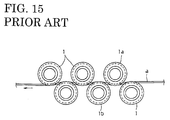
- the wire joint has been detected as follows. Since the wire joint is generally formed by twisting exposed conductors, a voltage is applied to a pair of opposite untwisting rollers 1 (1a, 1b in FIG. 15) provided along a running path of a wire a", so that the rollers 1a, 1b are electrically connected via the wire joint where the conductors are exposed when the wire joint comes to between the rollers 1a, 1b, thereby detecting the wire joint.
- the joint is detected by, e.g. a color sensor.
- a detection error may occur due to, for example, a defective contact between the wire a" and the rollers 1a, 1b. Further, the wire joint cannot be detected unless the conductors are exposed.
- the detection by the color sensor does not require the conductors to be exposed.
- the sensor itself is expensive, it is difficult to adjust the sensor for the detection and an error detection is frequently made.
- an object of the present invention is to provide wire connecting method and apparatus which have a high connection reliability and can be easily automated. Moreover, it is an object to provide a wire joint detection method and apparatus reliably allowing a detection of a wire joint, in particular regardless of whether or not conductors are exposed at the wire joint.
- a wire connecting method for connecting wires by placing the wires on the substantially same axis such that ends thereof substantially face each other and winding a tape over and around the ends of the wires, comprising the steps of:
- a tape is at least partly wound over and around ends of wires by substantially linearly aligning the wire ends to be connected in their longitudinal directions and rolling them.
- the tape is wound over and around the wire ends as the wire ends are rolled, thereby connecting the wires. Since the piece of tape displays a strong resistance to a tearing force acting in its longitudinal direction, the wires are strongly connected. Particularly, if the tape contains reinforced fibers, it displays a stronger tear resistance.
- one wire drawn from one of a plurality of wire supplies is replaced by an other wire drawn from an other one of the plurality of wire supplies while being guided to a wire processing apparatus, and connecting the two wires, wherein the end of the other wire is positioned substantially on the same axis as a cut end of the one wire after the one wire is cut on the base plate, and the both wire ends are then rolled to at least partly wind the tape over and around them.
- the above method can be employed when replacing one wire drawn from one of a plurality of wire supplies by an other wire drawn from an other one of the plurality of wire supplies while being guided to a wire processing apparatus midway, and connecting the two wires.
- the end of the other wire is positioned on the same axis as a cut end of the one wire after the one wire is cut on the base plate, and the both wire ends are then rolled to wind the tape over and around them.
- the both wire ends are rolled in an opposite direction to return to a path along which the wire is substantially drawn and guided.
- the wire ends are clamped and pulled in directions away from each other after the wires are connected by the tape to allow for a check whether or not the wire ends are or can be disengaged from each other, thereby judging whether or not the connection is satisfactory. Further, if the wire ends are clamped and pulled in directions away from each other after the wires are connected by the tape to check whether the wire ends are disengaged from each other, thereby judging whether or not the connection is satisfactory based on, the movement of the wire processing apparatus can be controlled in accordance with a connection judgment signal to prevent possible problems caused by a breakage of the wire and the like resulting from a defective connection.
- a wire joint detecting method for detecting a joint of two wires comprising the steps of:
- a wire joint makes a step on the outer surface of a wire regardless of which connecting means is employed and is designed to detect a joint by this step.
- a joint formed by twisting conductors of wires exposed by stripping sheaths at ends of the wires provides a step because the twisted portion of the conductors has a larger diameter or a step between the conductor and the sheath-coated portion of the wire. If the wires are connected by mounting a sleeve or welding, a step is also formed by the sleeve or a filling, respectively.
- the invention is then designed to detect the joint by rotating or pivoting a detector by a step formed by a joint of a running wire and actuating a switch by this rotation. If the detector is caught by the step, it is rotated or pivoted as the joint runs. The switch is actuated by this action to detect the joint.
- switches such as a micro switch and a photoelectric switch can be suitably selected as the above switch.
- the micro switch detects the joint of the wire by projection and retraction of an actuator resulting from the rotation of the detector, whereas the photoelectric switch detects it by a change in an amount of light detected thereby resulting from the rotation of the detector.
- a wire connecting apparatus in particular an automated wire connecting apparatus, preferably used in connection with a wire connecting method according to the invention or an embodiment thereof, comprising:
- the jigs are provided for drawing the tape from a roll of tape, substantially positioning it with respect to or aligning it substantially in parallel to the ends of the wires and cutting it to a specified length.
- the above construction there may be further provided jigs for clamping the wires on a wire drawing/guiding path which jigs are provided on the apparatus frame above and below the base plate, the one jig being movable upward along the wire drawing/guiding path. Then, the above connection judgment can be made by moving the one jig after the wires are clamped by the both jigs. In other words, the connection is satisfactory if the movement of the one jig stops at such a position where the wires are just straightened, whereas it is not satisfactory if the one jig moves beyond such a position.
- the wire connecting apparatus further comprises jigs for clamping the wires on a wire drawing/guiding path which jigs are provided on the apparatus frame on substantially opposed sides of or substantially above and below the base plate, wherein the one jig is movable away from the other jig or base plate, preferably substantially along or on the wire drawing/guiding path.
- the movable plate may be split into two sections for the one wire and the other wire, respectively, and the split sections of the movable plate may be (supported to be) elastically movable substantially toward and away from the wires. Then, even if diameters of the wires to be connected differ, the two split sections of the movable plate take up a diameter difference by elastically adjusting their distances to the wire ends, thereby enabling a smooth connection.
- a wire joint detecting apparatus in particular for use with a wire connecting apparatus according to the invention or an embodiment thereof, comprising:
- an operable plate and the detection switch which is actuated by a pivotal movement of the operable plate are provided on a frame, and the detector for coming into contact with the running wire is rotatably or pivotably mounted on the operable plate, and wherein the detector is rotated or pivoted by a step formed on the wire by the joint, the operable plate is pivoted by the rotation of the detector to actuate or activate the detection switch, and the joint of the wire is detected by a signal of the detection switch.
- the detection switch is a photoelectric switch
- the joint of the wire is detected by a change in an amount of light detected by the photoelectric switch resulting from the rotation of the detector.
- a surface of the detector to be held in sliding contact with the wire is formed by a substantially V-shaped groove in which the wire is at least partly fittable or insertable.
- a wire joint detecting apparatus for detecting a joint of two wires, in particular used in connection with a wire connecting apparatus according to the invention or an embodiment thereof, preferably used in connection with the wire joint detecting method according to the invention, comprising:
- the detector for pivoting the operable plate takes such a shape that a distance between a point of sliding contact with the wire and a center of rotation changes, for example, a polygon such as a rectangle or triangle.
- the center of the polygon serves as an axis of rotation. If surfaces of a V-shaped groove are employed as contact surfaces of the detector with the wire to increase points of contact (see e.g. FIG. 14), a joint can be detected even if it forms a small step, thereby improving a detection accuracy.
- the switch is actuated, for example, by having its actuator or the like pushed by the pivotal movement of the operable plate.
- a specific embodiment of the invention is such an operable plate and a detection switch which is actuated by a pivotal movement of the operable plate are provided on a frame, and a detector for coming into contact with a running wire is rotatably mounted on the operable plate, and wherein the detector is rotated by a step formed on the wire by a joint, the operable plate is pivoted by the rotation of the detector to actuate the detection switch, and the joint of the wire is detected by a signal of the detection switch.
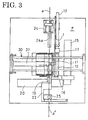
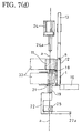
- FIGS. 1 to 8 One embodiment of the invention is shown in FIGS. 1 to 8. This embodiment is described mainly with reference to FIG. 1.
- An apparatus frame F is provided with a base plate 11 used for rolling wire ends (i.e. causing the wires or wire ends to pivot or rotate around their axis or around a direction of their longitudinal extension), a movable plate 33 used for rolling wire ends, a cutting device 18 for cutting a wire a", a transferring plate 19 onto which a wire to be connected is or can be transferred, and a tape drawing device 16 for drawing a tape t".
- a forcible wire withdrawing or dropping mechanism which forcibly withdraws the portion of the wire a" which is no longer needed, i.e.
- Such forcible wire withdrawing mechanism may include a withdrawing roller in contact or to be brought into contact with the portion of the wire a" to be withdrawn.
- the base plate 11 is secured to the frame F, and an auxiliary base plate 12 is so provided at one side of the base plate 11 as to be movable toward and away from the frame F by an unillustrated air cylinder or other moving or actuating means such as a step motor.
- the auxiliary base plate 12 is retracted toward the frame F when the tape drawing device 16 draws the tape t while being moved forward to be substantially flush with the base plate 11 when the tape t is wound around the wire a".
- a roll of tape 13 is provided above the base plate 11, and the tape t is or can be guided from the tape roll 13 to a position above the auxiliary base plate 12 via guide rollers 14a, 14b.
- the tape t has an adhesive layer formed on its inner surface in its rolled state, and slightly hangs down while having its adhesive layer adhered to the lower guide roller 14b.
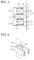
- the tape t is positioned on the auxiliary base plate 12 by clamping and lowering the hanging piece of the tape t by a clamping jig 16a of the vertically movable drawing device 16. At this time, as shown in FIG.
- one of clamping pieces 16b, 16c of the clamping jig 16a substantially facing to each other is supported via an insulating plate 16d such as a Bakelite plate, so that voltage is preferably applied to the clamping pieces 16b, 16c while providing an electrical insulation therebetween.
- an insulating plate 16d such as a Bakelite plate
- the clamping pieces 16b, 16c are brought into contact with each other to create an electrical connection, thereby enabling detection of the error clamping. If an error clamping signal is produced, succeeding operations are not performed.
- a tape pulling-down operation follows.
- the drawing device 16 is vertically moved by an unillustrated driving means provided in the guide 15.
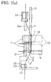
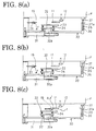
- the tape t After being pulled down by a specified length, the tape t is cut by a cutting device 17 and has its cut end pressed and supported by a probe provided in the cutting device 17 (at point S in FIG. 7(d)).
- the tape t is released when the cutting device 17 is moved forward at a moment when the wire a" is brought to an end position of the tape t by the movable plate 33 to be described later.
- the drawing device 16 is retracted forward. Accordingly, the movement of the movable plate 33 is neither interfered nor hindered.
- the cutting device 17 is reciprocatingly moved preferably forward and backward preferably by an air cylinder 17a, and the drawing device 16 are caused to clamp the tape t and retract by opening and closing movements and a retracting movement (forward movement) of the clamping jig 16a at its leading end. These movements are preferably caused by an unillustrated air cylinder.
- the base plate 11 is preferably split into first or upper and second or lower sections, between which the cutting device 18 is provided.
- the cutting device 18 is actuated by an air cylinder 18a to cut the wire a" substantially vertically guided and clamps the upper part of the cut wire a".
- the cutting device 18 releases the wire a" at a moment when or after the wire a" is clamped between the movable plate 33 and the base plate 11, and is substantially retracted into a clearance between the upper and lower sections of the base plate 11.
- the movable plate 33 is preferably also split into first or upper and second or lower sections. Since being located between the upper and lower sections of the movable plate 33, the cutting device 18 neither interferes nor hinders the movement of the movable plate 33.
- the transferring plate 19 is transversely movable by a guide 20.
- a wire a'" to be connected is laterally inserted into clips 21 e.g. from the right side to be clamped and supported.
- the transferring plate 19 is transversely moved or moved in a direction at an angle different from 0° or 180°, preferably substantially normal with respect to the direction of extension of the wires a/a' by an unillustrated driving means provided in the guide 20.
- a U-shaped arm 22 is provided below the transferring plate 19, and the wire a'" is inserted into a clip 23 provided in an intermediate position of the arm 22 e.g. from the right side to be clamped.
- the arm 22 also drives away the lower part of the wire a'" cut by a leading end 22a of the arm 22, so that this lower part of the wire a'" does not stand as a hindrance.
- Guiding jigs 24, 25 each provided with a chuck are provided on the frame F at substantially opposed sides of or above and below the base plate 11, respectively.
- the upper guiding jig 24 moves upward while clamping the wire a" by means of the chuck upon being actuated by an air cylinder 24a.
- the lower guiding jig 25 clamps and fixes or positions the wire a'" upon being actuated by an air cylinder 25a.
- the upper and lower guiding jigs 24, 25 clamp the wires a", a'" while the upper guiding jig 24 moves upward, thereby straightening the wires a", a'" to judge as to whether the tape t has been satisfactorily wound as described later.
- An auxiliary frame 30 is provided on the front surface of the base plate 11 of the frame F such that it is pivotal preferably along forward and backward directions about its left end.
- a movable plate 32 is so provided on the frame 30 via a slider 32a as to be transversely movable by an air cylinder 31.
- the movable plate 33 preferably split into upper and lower sections is provided.
- the movable plate 33 is so supported on the movable plate 32 as to be movable toward and away from the movable plate 32, and is preferably biased in a direction away from the movable plate 32 by biasing means such as springs 34. Therefore, as shown in FIG.
- the movable plate 33 smoothly holds the wires a", a'" in cooperation with the base plate 11 by the elastic force of the springs 34 even if the diameters of the wires a", a'" differ when the movable plate 33 is pressed into contact with the base plate 11 with the wires a", a'" provided therebetween.
- Stoppers 35 are provided at the leading end of the frame 30.
- the length of the stoppers 35 is adjustable, and a contact degree (degree of proximity or distance) of the movable plate 33 with respect to the base plates 11, 12 can be adjusted by adjusting the length of the stoppers 35.
- This adjustment is effective in preventing abrasion of the outer surfaces of the plates 33, 11, 12.
- a non-slip layer to which e.g. sand-like particles are adhered is formed on the contact surface of each of the plates 11, 12, 19 and 33 so that the wires a", a'" can be smoothly rolled.
- the contact degree By adjusting the contact degree, the abrasion of the non-slip layers can be prevented.
- a piston rod 37a of an air cylinder 37 fixed to the frame F is coupled to or fixed with a hook 36 at the leading end of the frame 30 via a pin.
- the frame 30 is pulled toward the base plate 11 by the actuation of the air cylinder 37, thereby bringing the movable plate 33 substantially into contact (or closer to) the base plate 11 and the like with the wires a", a'" located therebetween.
- the movable plate 33 is moved to the right by actuating the air cylinder 31 to wind the tape t over and around the wires a", a'" by rolling the wires a", a'".
- the clips 21, 23 are provided with clamp completion switches. At this stage, unless these switches are on, the connecting operation is preferably not started even if the start switch is turned on. This is because a connection error is likely to occur if the wires a", a'" are insufficiently clamped by the clips 21, 23.
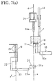
- connection operation is performed as follows. First, in the state shown in FIGS. 2, 7(a) and 8(a), the tape drawing device 16 is moved upward to clamp the tape t by means of the clamping jig 16a (see FIGS. 7(b) and 8(b)), and draws the tape t so as to at least partly extend it substantially along the auxiliary base plate 12 (see FIGS. 7(c) and 8(c)). Simultaneously with the completion of this operation, the tape t is cut and the transferring plate 19 is moved to the right to abut against the lower base plate 11 (see FIGS. 7(c) and 8(c)).
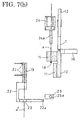
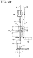
- the frame 30 is moved closer to the frame F so that the movable plate 33 comes into contact with (closer to) the base plate 11 with the wires a", a'" located therebetween (see FIGS. 7(d) and 8(d)), and the movable plate 33 is moved to the right (see FIGS. 7(e) and 8(e)).
- the wires a", a'" are rolled between the base plate 11 and the movable plate 33 (preferably due to a relative movement thereof along a direction at an angle different from 0° or 180°, preferably substantially normal to the extension direction of the wire(s) a/a') and, consequently, are rolled on the tape t on the auxiliary base plate 12.
- the tape t is wound over and around the wires a", a'" to substantially connect or join them as shown in FIG. 9 (see FIGS. 7(e) and 8(e)).
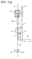
- the movable plate 33 is moved to the left to untwist the wires a", a'" (see FIGS. 7(f) and 8(f)), and the frame 30 is moved away from the frame F to return the movable plate 33 to its initial position.
- the upper and lower guiding jigs 24, 25 clamp the wires a", a'" and the upper guiding jig 24 is moved upward to judge whether or not the connection is satisfactory (see FIGS. 7(g) and 8(g)).
- the above operations are performed to automatically connect the wires a", a'" when the wires a", a'" are exchanged.
- the inventive method and apparatus thus constructed achieve a high connection reliability and easily enable automation of the wire connection.
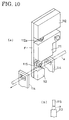
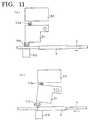
- FIGS. 10 and 11 show one embodiment of the invention, which is provided in a wire running path to a wire processing apparatus such as a wire cutting/crimping apparatus.
- An operable plate 111 is pivotally or rotatably provided on a frame F, and a micro switch 112 is provided above or in proximity of the operable plate 111 in a direction of movement thereof.
- a micro switch 112 is provided above or in proximity of the operable plate 111 in a direction of movement thereof.
- an actuator 112a is pushed up to actuate the micro switch 112.
- any other detector sensing a pivotal movement such as a proximity sensor, a light/diode sensor or the like may be used.
- a wire contacting jig 113 and a guide 114 are provided on the frame F below or at an opposite side of the operable plate 111, and a wire a" runs through or on the wire contacting jig 113 and the guide 114.
- a substantially rectangular detector 115 rotatable about its center axis is provided at an end of the operable plate 111 substantially facing the wire contacting jig 113. One side of the detector 115 is constantly held in sliding contact with the wire a" running on the wire contacting jig 113.
- the operable plate 111 is substantially not pivoted or rotated away from the wire a e.g. upward, i.e. the micro switch 112 is not turned on as shown in FIG. 11(a).
- the succeeding side of the rotated detector 115 comes into sliding contact with the wire a" (joint t"), and the operable plate 111 is pivoted downward to return substantially to its normal state for detecting a next joint t".
- the joints t" of the wire a" are successively detected by repeating the above operation.
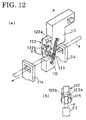
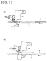
- FIGS. 12 and 13 show an embodiment in which a photoelectric switch 122 is used instead of the micro switch 112.
- a spring 123 is provided between the operable plate 111 and the wire contacting jig 113, so that the detector 115 can be securely held in sliding contact with the wire a" by a biasing force of the spring 123.
- the photoelectric switch 122 is comprised of a light detector 122a and a light emitter 122b mounted on the operable plate 111 with the detector 115 located therebetween.
- the operable plate 111 is substantially not pivoted or rotated upward as shown in FIG. 13 and, accordingly, a light present between the light detector 122a and the light emitter 122b of the photoelectric switch 122 is not blocked by the detector 115. If a joint formed e.g. by a tape t" reaches the wire contacting jig 113 in this state, the detector 115 is rotated or pivoted as shown in FIG. 13(b) and in phantom in FIG. 12(b), thereby blocking the light between the light detector 122a and the light emitter 122b as indicated by hatching in FIG. 13(b), with the result that the photoelectric switch 122 is actuated in response to a change in an amount of light detected thereby to detect the joint t" of the wire a".
- the operable plate 111 (detector 115) and the jig 113 may be electrically insulated from each other by making the frame F of an insulating plate such as a Bakelite plate, and a voltage may be applied to between the plate 111 and the jig 113 to detect a joint formed by twisting conductors of the wires as described above.
- the joint can be detected by an electrical connection established between the detector 115 and the jig 113 by the joint t".
- joint is detected by the wound tape t in this embodiment, other known joints formed by twisting the conductors or mounting a sleeve can also be detected if there is a step.
- the joint is detected by its step as described above in the present invention, it can be securely detected without any restriction factor such as the exposure of the conductors.
Landscapes
- Manufacturing Of Electrical Connectors (AREA)
- Supply And Installment Of Electrical Components (AREA)
- Ropes Or Cables (AREA)
- Processing Of Terminals (AREA)
Applications Claiming Priority (6)
| Application Number | Priority Date | Filing Date | Title |
|---|---|---|---|
| JP22612499 | 1999-08-10 | ||
| JP22613099A JP3639749B2 (ja) | 1999-08-10 | 1999-08-10 | 電線接続方法及び電線自動接続装置 |
| JP22612499 | 1999-08-10 | ||
| JP22613099 | 1999-08-10 | ||
| JP2000216193 | 2000-07-17 | ||
| JP2000216193A JP3881163B2 (ja) | 1999-08-10 | 2000-07-17 | 電線つなぎ目検出装置 |
Publications (3)
| Publication Number | Publication Date |
|---|---|
| EP1076385A2 true EP1076385A2 (fr) | 2001-02-14 |
| EP1076385A3 EP1076385A3 (fr) | 2002-05-08 |
| EP1076385B1 EP1076385B1 (fr) | 2004-10-27 |
Family
ID=27331128
Family Applications (1)
| Application Number | Title | Priority Date | Filing Date |
|---|---|---|---|
| EP20000116871 Expired - Lifetime EP1076385B1 (fr) | 1999-08-10 | 2000-08-04 | Un procédé de connexion de fils et un dispositif de connexion de fils |
Country Status (3)
| Country | Link |
|---|---|
| US (3) | US6685786B1 (fr) |
| EP (1) | EP1076385B1 (fr) |
| DE (1) | DE60015252T2 (fr) |
Cited By (6)
| Publication number | Priority date | Publication date | Assignee | Title |
|---|---|---|---|---|
| EP3065221A1 (fr) * | 2015-03-03 | 2016-09-07 | Delphi Technologies, Inc. | Procédé permettant d'établir une connexion entre au moins deux câbles et dispositif permettant de fournir une connexion de câble isolé |
| CN109590724A (zh) * | 2018-12-26 | 2019-04-09 | 中国科学院长春光学精密机械与物理研究所 | 一种片状器件立式装调方法 |
| CN112093588A (zh) * | 2019-06-18 | 2020-12-18 | 卓郎纺织解决方案两合股份有限公司 | 用于纱线连接装置的摩擦盘 |
| CN112398051A (zh) * | 2020-10-22 | 2021-02-23 | 衡阳市捷讯实业有限公司 | 一种电线生产的线材穿套管成型装置 |
| CN117260254A (zh) * | 2023-09-21 | 2023-12-22 | 厦门同智科技有限公司 | 一种柱型灯装配生产线 |
| CN119764961A (zh) * | 2024-12-30 | 2025-04-04 | 东莞海弘智能科技有限公司 | 一种全自动单头套管缠胶布插壳机 |
Families Citing this family (7)
| Publication number | Priority date | Publication date | Assignee | Title |
|---|---|---|---|---|
| US7189940B2 (en) * | 2002-12-04 | 2007-03-13 | Btu International Inc. | Plasma-assisted melting |
| FR2962250B1 (fr) * | 2010-07-05 | 2014-05-02 | Laselec | Procede de marquage d'un cable, machine de marquage de cables et allonge pour cable |
| TWI693417B (zh) * | 2018-12-12 | 2020-05-11 | 裕群精密科技有限公司 | 電子線夾測試機 |
| CN114639520B (zh) | 2020-12-15 | 2025-07-15 | 泰科电子(上海)有限公司 | 检测机构、导线定位装置及导线加工设备 |
| CN112787115A (zh) * | 2021-01-21 | 2021-05-11 | 昆山沪光汽车电器股份有限公司 | 一种新能源汽车导线线夹 |
| CN115995775B (zh) * | 2023-03-23 | 2023-05-30 | 云南百冠电线电缆有限公司 | 一种5g建设线缆铺设定位导向设备及方法 |
| CN119381856B (zh) * | 2024-12-30 | 2025-03-14 | 常州锐迪夫电子科技有限公司 | 一种线束焊接装置 |
Family Cites Families (21)
| Publication number | Priority date | Publication date | Assignee | Title |
|---|---|---|---|---|
| US2279299A (en) * | 1940-11-05 | 1942-04-14 | John F Cavanagh | Splicer for rubber thread |
| US2279300A (en) * | 1941-10-16 | 1942-04-14 | John F Cavanagh | Method of splicing rubber thread |
| JPS52102787A (en) * | 1976-02-25 | 1977-08-29 | Kobe Steel Ltd | Method of detecting abnormal state of continuously traveling wire |
| GB2024052B (en) * | 1978-06-15 | 1982-07-14 | Lansing Bagnall Ltd | Method and apparatus for wiring loom production |
| DE3144281A1 (de) | 1981-11-07 | 1983-05-19 | Peter Dipl.-Wirtsch.-Ing. 6101 Fränkisch-Crumbach Born | Verfahren und vorrichtung zur vorbereitung der anschlussenden von dreiadrigen beweglichen elektrischen leitungen |
| US4607430A (en) * | 1984-11-13 | 1986-08-26 | Westinghouse Electric Corp. | Method and apparatus for high density wire harness manufacture |
| US4832767A (en) * | 1988-01-28 | 1989-05-23 | Eller Donald G | Wire splice wrapping apparatus and method |
| US5226995A (en) * | 1991-05-28 | 1993-07-13 | The Rockefeller University | Method and apparatus for joining plastic optical fibers |
| JPH05345324A (ja) * | 1992-06-16 | 1993-12-27 | Furukawa Electric Co Ltd:The | 絶縁電線への電子線照射方法 |
| JPH0624319A (ja) | 1992-07-08 | 1994-02-01 | Mazda Motor Corp | 車両のアンチスキッドブレ−キ装置 |
| JP2930282B2 (ja) | 1993-04-26 | 1999-08-03 | 矢崎総業株式会社 | ジョイント検出機構を備えた電線送り装置 |
| JPH0714446A (ja) * | 1993-06-24 | 1995-01-17 | Matsushita Electric Works Ltd | 自動配線装置 |
| JPH0878128A (ja) | 1994-09-08 | 1996-03-22 | Sumitomo Wiring Syst Ltd | 粘着テープの巻き付け装置 |
| JP3026726B2 (ja) | 1994-11-11 | 2000-03-27 | 矢崎総業株式会社 | 電線ジョイント装置及びジョイント電線製造方法 |
| DE69510021T2 (de) * | 1994-12-15 | 2000-02-03 | Sumitomo Wiring Systems, Ltd. | Einrichtung zur Lagekorrektur eines Drahtes |
| JP2915346B2 (ja) | 1996-05-01 | 1999-07-05 | 株式会社フジクラ | 電力ケーブルの絶縁テープ巻き付け装置 |
| JP3470500B2 (ja) | 1996-05-20 | 2003-11-25 | 住友電装株式会社 | テーピングホイールおよびそれを用いたテープ巻き装置 |
| JPH103979A (ja) * | 1996-06-14 | 1998-01-06 | Yazaki Corp | 定尺電線の製造方法および装置 |
| JP3314626B2 (ja) | 1996-09-12 | 2002-08-12 | 住友電装株式会社 | 自己診断機能付電線除去部分検出装置 |
| JPH1167286A (ja) | 1997-08-18 | 1999-03-09 | Sumitomo Wiring Syst Ltd | 電線連結装置および連結スリーブ |
| JP3324485B2 (ja) * | 1998-01-23 | 2002-09-17 | 住友電装株式会社 | テーピング装置 |
-
2000
- 2000-08-04 EP EP20000116871 patent/EP1076385B1/fr not_active Expired - Lifetime
- 2000-08-04 US US09/632,963 patent/US6685786B1/en not_active Expired - Lifetime
- 2000-08-04 DE DE60015252T patent/DE60015252T2/de not_active Expired - Lifetime
-
2002
- 2002-10-03 US US10/265,888 patent/US7036544B2/en not_active Expired - Lifetime
- 2002-10-09 US US10/268,492 patent/US6936124B2/en not_active Expired - Lifetime
Cited By (9)
| Publication number | Priority date | Publication date | Assignee | Title |
|---|---|---|---|---|
| EP3065221A1 (fr) * | 2015-03-03 | 2016-09-07 | Delphi Technologies, Inc. | Procédé permettant d'établir une connexion entre au moins deux câbles et dispositif permettant de fournir une connexion de câble isolé |
| CN105938941A (zh) * | 2015-03-03 | 2016-09-14 | 戴尔菲技术公司 | 在电缆间提供连接的方法和用于提供绝缘电缆连接的设备 |
| CN109590724A (zh) * | 2018-12-26 | 2019-04-09 | 中国科学院长春光学精密机械与物理研究所 | 一种片状器件立式装调方法 |
| CN112093588A (zh) * | 2019-06-18 | 2020-12-18 | 卓郎纺织解决方案两合股份有限公司 | 用于纱线连接装置的摩擦盘 |
| CN112093588B (zh) * | 2019-06-18 | 2022-09-02 | 卓郎纺织解决方案两合股份有限公司 | 用于纱线连接装置的摩擦盘 |
| CN112398051A (zh) * | 2020-10-22 | 2021-02-23 | 衡阳市捷讯实业有限公司 | 一种电线生产的线材穿套管成型装置 |
| CN112398051B (zh) * | 2020-10-22 | 2022-07-26 | 潮州市朝辉电器有限公司 | 一种电线生产的线材穿套管成型装置 |
| CN117260254A (zh) * | 2023-09-21 | 2023-12-22 | 厦门同智科技有限公司 | 一种柱型灯装配生产线 |
| CN119764961A (zh) * | 2024-12-30 | 2025-04-04 | 东莞海弘智能科技有限公司 | 一种全自动单头套管缠胶布插壳机 |
Also Published As
| Publication number | Publication date |
|---|---|
| US20030034461A1 (en) | 2003-02-20 |
| US6685786B1 (en) | 2004-02-03 |
| US20030029574A1 (en) | 2003-02-13 |
| DE60015252D1 (de) | 2004-12-02 |
| DE60015252T2 (de) | 2006-02-02 |
| EP1076385A3 (fr) | 2002-05-08 |
| EP1076385B1 (fr) | 2004-10-27 |
| US7036544B2 (en) | 2006-05-02 |
| US6936124B2 (en) | 2005-08-30 |
Similar Documents
| Publication | Publication Date | Title |
|---|---|---|
| EP1076385A2 (fr) | Un procédé de connexion de fils, un procédé de détection de connexion de fils, un dispositif de connexion de fils et un dispositif de détection de connexion de fils | |
| US5138910A (en) | Electrical cable stripping method and stripping device | |
| EP0531912B1 (fr) | Machine et procédé pour la connection de faisceaux électriques | |
| US6363604B1 (en) | Method and apparatus for cutting braided sheath of shielding wire | |
| EP0117273A1 (fr) | Appareil pour fixer automatiquement des connecteurs à des fins de câbles | |
| JPH0684577A (ja) | 端子挿入装置 | |
| EP0667658B1 (fr) | Dispositif et procédé pour mesurer la hauteur de sertissage | |
| EP0615317B1 (fr) | Dispositif de guidage de câble électrique | |
| US4622733A (en) | Branch wire connecting apparatus | |
| EP4718643A1 (fr) | Appareil et procédé de coupe et d'insertion de conducteur externe | |
| EP4285449B1 (fr) | Dispositif de sertissage de borne électrique qui empêche le retrait de sertissage défectueux | |
| US20050132770A1 (en) | Wire-processing device | |
| EP0753911B1 (fr) | Dispositif de guidage et de coupage de fils | |
| EP0356252A2 (fr) | Dispositif de terminaison aux deux extrémités et de pose pour un système de câblage automatique | |
| JPH0877846A (ja) | 電気ハ−ネス製造装置 | |
| JPH06231860A (ja) | 端子挿入装置 | |
| JP4094188B2 (ja) | 被覆電線の皮剥き方法および装置 | |
| US20250309600A1 (en) | Twisted Pair Cable Processing System, Twisted Pair Cable Cutting Method and Untwisting Method | |
| JP2908717B2 (ja) | 丸形二芯電源コードへのプラグ端子の圧着方法及びその装置 | |
| JPH0650287U (ja) | 電線の測長装置 | |
| JPH0555994B2 (fr) | ||
| JPH03280376A (ja) | ケーブルをコネクタに装着する装置 | |
| JPH10321063A (ja) | フラットハーネス製造治具 | |
| JP2000123654A (ja) | 識別装置及び識別方法 | |
| JPH0650285U (ja) | 多芯ケーブルの布線装置 |
Legal Events
| Date | Code | Title | Description |
|---|---|---|---|
| PUAI | Public reference made under article 153(3) epc to a published international application that has entered the european phase |
Free format text: ORIGINAL CODE: 0009012 |
|
| 17P | Request for examination filed |
Effective date: 20000831 |
|
| AK | Designated contracting states |
Kind code of ref document: A2 Designated state(s): AT BE CH CY DE DK ES FI FR GB GR IE IT LI LU MC NL PT SE |
|
| AX | Request for extension of the european patent |
Free format text: AL;LT;LV;MK;RO;SI |
|
| PUAL | Search report despatched |
Free format text: ORIGINAL CODE: 0009013 |
|
| AK | Designated contracting states |
Kind code of ref document: A3 Designated state(s): AT BE CH CY DE DK ES FI FR GB GR IE IT LI LU MC NL PT SE |
|
| AX | Request for extension of the european patent |
Free format text: AL;LT;LV;MK;RO;SI |
|
| RIC1 | Information provided on ipc code assigned before grant |
Free format text: 7H 01R 43/00 A, 7H 01R 4/12 B, 7H 01R 4/70 B, 7H 01R 43/28 B, 7H 02G 1/14 B |
|
| AKX | Designation fees paid |
Designated state(s): DE FR GB |
|
| 17Q | First examination report despatched |
Effective date: 20031001 |
|
| GRAP | Despatch of communication of intention to grant a patent |
Free format text: ORIGINAL CODE: EPIDOSNIGR1 |
|
| RTI1 | Title (correction) |
Free format text: A WIRE CONNECTING METHOD AND A WIRE CONNECTING APPARATUS |
|
| GRAS | Grant fee paid |
Free format text: ORIGINAL CODE: EPIDOSNIGR3 |
|
| GRAA | (expected) grant |
Free format text: ORIGINAL CODE: 0009210 |
|
| AK | Designated contracting states |
Kind code of ref document: B1 Designated state(s): DE FR GB |
|
| REG | Reference to a national code |
Ref country code: GB Ref legal event code: FG4D |
|
| REG | Reference to a national code |
Ref country code: IE Ref legal event code: FG4D |
|
| REF | Corresponds to: |
Ref document number: 60015252 Country of ref document: DE Date of ref document: 20041202 Kind code of ref document: P |
|
| ET | Fr: translation filed | ||
| PG25 | Lapsed in a contracting state [announced via postgrant information from national office to epo] |
Ref country code: GB Free format text: LAPSE BECAUSE OF NON-PAYMENT OF DUE FEES Effective date: 20050804 |
|
| PLBE | No opposition filed within time limit |
Free format text: ORIGINAL CODE: 0009261 |
|
| STAA | Information on the status of an ep patent application or granted ep patent |
Free format text: STATUS: NO OPPOSITION FILED WITHIN TIME LIMIT |
|
| 26N | No opposition filed |
Effective date: 20050728 |
|
| GBPC | Gb: european patent ceased through non-payment of renewal fee |
Effective date: 20050804 |
|
| PGFP | Annual fee paid to national office [announced via postgrant information from national office to epo] |
Ref country code: DE Payment date: 20120731 Year of fee payment: 13 Ref country code: FR Payment date: 20120823 Year of fee payment: 13 |
|
| PG25 | Lapsed in a contracting state [announced via postgrant information from national office to epo] |
Ref country code: DE Free format text: LAPSE BECAUSE OF NON-PAYMENT OF DUE FEES Effective date: 20140301 |
|
| REG | Reference to a national code |
Ref country code: DE Ref legal event code: R119 Ref document number: 60015252 Country of ref document: DE Effective date: 20140301 |
|
| REG | Reference to a national code |
Ref country code: FR Ref legal event code: ST Effective date: 20140430 |
|
| PG25 | Lapsed in a contracting state [announced via postgrant information from national office to epo] |
Ref country code: FR Free format text: LAPSE BECAUSE OF NON-PAYMENT OF DUE FEES Effective date: 20130902 |