EP1077138A1 - Impression en ligne et traitement par étapes de matériel en bande - Google Patents
Impression en ligne et traitement par étapes de matériel en bande Download PDFInfo
- Publication number
- EP1077138A1 EP1077138A1 EP99202655A EP99202655A EP1077138A1 EP 1077138 A1 EP1077138 A1 EP 1077138A1 EP 99202655 A EP99202655 A EP 99202655A EP 99202655 A EP99202655 A EP 99202655A EP 1077138 A1 EP1077138 A1 EP 1077138A1
- Authority
- EP
- European Patent Office
- Prior art keywords
- printing
- band material
- transport path
- advancing
- processing
- Prior art date
- Legal status (The legal status is an assumption and is not a legal conclusion. Google has not performed a legal analysis and makes no representation as to the accuracy of the status listed.)
- Withdrawn
Links
- 239000000463 material Substances 0.000 title claims abstract description 124
- 238000007639 printing Methods 0.000 title claims abstract description 119
- 238000012545 processing Methods 0.000 title claims abstract description 53
- 230000015572 biosynthetic process Effects 0.000 claims abstract description 10
- 238000011144 upstream manufacturing Methods 0.000 claims description 13
- 238000000034 method Methods 0.000 claims description 11
- 238000007789 sealing Methods 0.000 description 71
- 239000003566 sealing material Substances 0.000 description 16
- 238000004080 punching Methods 0.000 description 8
- 230000005540 biological transmission Effects 0.000 description 7
- 239000006187 pill Substances 0.000 description 6
- 230000008901 benefit Effects 0.000 description 5
- 239000005022 packaging material Substances 0.000 description 5
- 238000004806 packaging method and process Methods 0.000 description 4
- 238000013461 design Methods 0.000 description 3
- 230000000694 effects Effects 0.000 description 3
- 229910000838 Al alloy Inorganic materials 0.000 description 2
- 230000009471 action Effects 0.000 description 2
- 230000006978 adaptation Effects 0.000 description 2
- 238000006073 displacement reaction Methods 0.000 description 2
- 230000008569 process Effects 0.000 description 2
- 230000000717 retained effect Effects 0.000 description 2
- 230000004913 activation Effects 0.000 description 1
- XAGFODPZIPBFFR-UHFFFAOYSA-N aluminium Chemical compound [Al] XAGFODPZIPBFFR-UHFFFAOYSA-N 0.000 description 1
- 229910052782 aluminium Inorganic materials 0.000 description 1
- 230000004888 barrier function Effects 0.000 description 1
- 239000002775 capsule Substances 0.000 description 1
- 238000010276 construction Methods 0.000 description 1
- 238000005520 cutting process Methods 0.000 description 1
- 230000001419 dependent effect Effects 0.000 description 1
- 238000004519 manufacturing process Methods 0.000 description 1
- 239000011159 matrix material Substances 0.000 description 1
- 230000009467 reduction Effects 0.000 description 1
- 230000004044 response Effects 0.000 description 1
- 238000007651 thermal printing Methods 0.000 description 1
- 238000012546 transfer Methods 0.000 description 1
- 238000012795 verification Methods 0.000 description 1
Images

Classifications
-
- B—PERFORMING OPERATIONS; TRANSPORTING
- B41—PRINTING; LINING MACHINES; TYPEWRITERS; STAMPS
- B41J—TYPEWRITERS; SELECTIVE PRINTING MECHANISMS, i.e. MECHANISMS PRINTING OTHERWISE THAN FROM A FORME; CORRECTION OF TYPOGRAPHICAL ERRORS
- B41J15/00—Devices or arrangements of selective printing mechanisms, e.g. ink-jet printers or thermal printers, specially adapted for supporting or handling copy material in continuous form, e.g. webs
- B41J15/16—Means for tensioning or winding the web
-
- B—PERFORMING OPERATIONS; TRANSPORTING
- B41—PRINTING; LINING MACHINES; TYPEWRITERS; STAMPS
- B41J—TYPEWRITERS; SELECTIVE PRINTING MECHANISMS, i.e. MECHANISMS PRINTING OTHERWISE THAN FROM A FORME; CORRECTION OF TYPOGRAPHICAL ERRORS
- B41J11/00—Devices or arrangements of selective printing mechanisms, e.g. ink-jet printers or thermal printers, for supporting or handling copy material in sheet or web form
- B41J11/36—Blanking or long feeds; Feeding to a particular line, e.g. by rotation of platen or feed roller
- B41J11/42—Controlling printing material conveyance for accurate alignment of the printing material with the printhead; Print registering
-
- B—PERFORMING OPERATIONS; TRANSPORTING
- B41—PRINTING; LINING MACHINES; TYPEWRITERS; STAMPS
- B41J—TYPEWRITERS; SELECTIVE PRINTING MECHANISMS, i.e. MECHANISMS PRINTING OTHERWISE THAN FROM A FORME; CORRECTION OF TYPOGRAPHICAL ERRORS
- B41J15/00—Devices or arrangements of selective printing mechanisms, e.g. ink-jet printers or thermal printers, specially adapted for supporting or handling copy material in continuous form, e.g. webs
- B41J15/005—Forming loops or sags in webs, e.g. for slackening a web or for compensating variations of the amount of conveyed web material (by arranging a "dancing roller" in a sag of the web material)
-
- B—PERFORMING OPERATIONS; TRANSPORTING
- B41—PRINTING; LINING MACHINES; TYPEWRITERS; STAMPS
- B41J—TYPEWRITERS; SELECTIVE PRINTING MECHANISMS, i.e. MECHANISMS PRINTING OTHERWISE THAN FROM A FORME; CORRECTION OF TYPOGRAPHICAL ERRORS
- B41J15/00—Devices or arrangements of selective printing mechanisms, e.g. ink-jet printers or thermal printers, specially adapted for supporting or handling copy material in continuous form, e.g. webs
- B41J15/04—Supporting, feeding, or guiding devices; Mountings for web rolls or spindles
Definitions
- the invention relates to a method according to the introductory portion of claim 1 for in-line printing and processing of successive portions of a band material.
- the invention further relates to a system according to the introductory portion of claim 7 and to a printer according to the introductory portion of claim 13.
- Such a method such a system and such a printer are known from U.S. patent specification 4,559,755.
- the printing is applied by flexoprinting to a strip of packaging material, usually aluminum, which is fed along the transport path to a processing station where the packaging material is sealed to a strip of blisters.
- the blisters have previously been formed in a sequence of steps along another transport path.
- the effective length of band material between the position where the flexoprinting roll contacts the packaging material and the processing station where the backing of the blisters is sealed to the blisters containing the products to be packaged is adjustable.
- In-line flexoprinting allows the backing to be printed on demand, in accordance with the amount of products being packaged and the printing can be formed as packaging material is fed to the position where it is processed and is thereby automatically aligned in transport direction with the blisters to be sealed to the packaging material.
- a disadvantage of flexoprinting is that changing from one image to be printed to another image to be printed is cumbersome in that it requires changing the printer block. Moreover, for each design to be printed, a different printing block is needed which entails substantial costs per design and the need of keeping a stock of all designs one desires to be print.
- this object is achieved by providing a method according to claim 1.
- Another embodiment of the present invention is formed by a system according to claim 7.
- the present invention can also be embodied in a printer according to claim 13 which is specifically adapted to be included in a system according to claim 7 in combination with generally available processing facilities.
- the printing is carried out incrementally and in conjunction with incrementally advancing the portion to be printed in accordance with the formation of the incremental portions of the printing, such that the printing is formed, changes in the printing to be made can be made easily by changing data determining the way the printing member is controlled.
- the printed portion is advanced over a remaining portion of the predetermined distance after having been printed, it is assured in a simple manner that the printings are aligned with the positions on the band material onto which the processing is performed. This can be upstream or downstream of the printing position.
- the predetermined total distance of displacement of the band material between the printing station and processing station assures that the printing is aligned in transport direction with the position on the band material onto which the processing step is performed when the transfer of respective portion of the band material between the printing position and the processing position is completed.
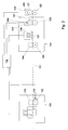
- the system for in-line printing and processing of successive portions of a band material as shown in Fig. 1 forms the presently most preferred embodiment of the present invention. It is based on a combination of a commercially available packaging apparatus and a modified commercially available printer. Therefore details of the packaging apparatus and the printer are not described extensively. Both the packaging apparatus and the printer can be of various types, depending on the requirements regarding for instance size and capacity which need to be fulfilled.
- a transport path 1 for transporting band material - in this example in the form of back sealing material for blister packages - extends across this system.
- the band material to be printed and processed extends along the transport path 1.
- the transport path 1 starts at a support 2 carrying a feeding roll 3, along a printer 4, a processing station 6 and a punching station 58. Downstream of the punching station 58, the band material splits up in a band 60 of remaining material which is left over after packages have been punched out at the punching machine 58 and a line 61 of blister packages.
- the band 60 of remaining material extends to a collecting roll 7.
- the collecting roll 7 is carried by a collecting roll support 8 including a drive for pulling band material along the track 1.
- the printer 4 includes a printhead 5 along the transport path 1.
- the processing station is formed by a sealing station 6.
- the course of the transport path 1 is determined by a plurality of guide rolls 9-25. Some of the guide rolls are arranged for performing other functions than guiding the band material as well, as is described below.
- Particularly suitable materials for the band of back sealing material are aluminum alloys, which stretch little under tension and also show relatively little extension and shrinkage under influence of temperature and humidity.
- aluminum alloy film is a very effective barrier material.
- an advancing structure For advancing band material along the transport path, an advancing structure is provided.
- the most upstream part of the advancing structure is formed by the support 2 of the feeding roll 3, which is provided with a friction brake (not shown) to keep the portion of the band material upstream of the printer 4 tensioned.
- the next part of the advancing structure is formed by a pair of rollers 31, 32 of the printer 4.
- the roller 31 is connected to a motor 33 via a transmission wheel 34.
- the motor 33 is operatively connected to a printer control system 35 adapted to control the motor 34 for rotation in accordance with the progress of the printing process carried out by the printhead 5.
- This printhead 5 is adapted and controlled for incrementally printing successive line portions of a printing to be made.
- the printhead 5 is operatively connected to the printer control system 35 as well.
- the printer control system 35 is adapted for controlling the printhead 5 and the motor 33 in a coordinated manner such that images are formed in accordance with instructions obtained from a control system 30 connected thereto.
- Suitable printer engines operating in accordance with this principle are commercially available in various forms, such as in the form of laser printers, matrix printers and ink jet printers. Therefore, the printer 4 is not described in detail. According to the present example, the construction of the printer 4 is based on a thermal printer commercially available from TEC Corporation, 570 Ohito, Ohito-cho, Tagata-Gun, Shizuoka-Ken 410-23, Japan.
- the feeder structure of the sealing station 6 includes transport rollers 26, 27 and a motor 29 to which the transport roller 27 is connected via a transmission wheel 28.
- the motor 29 is connected to the control system 30 for stepwise feeding material to the sealing station 6 in response to activation signals received from the control system 30. More in particular, this control system 30 is adapted to activate the motor 29 for rotation over a predetermined angle, each time the band of material is to be shifted forward one position for bringing a new portion of the band material in a position to be processed in the sealing station 6.
- This distance is preferably adjustable in accordance with the displacement required by the sealing steps to be performed at the sealing station 6 - for instance in accordance with the size in transport direction of the packages to be sealed.
- An example of such a sealing station is described in U.S. patent specification 4,559,755.
- the collecting roll support 8 forms the most downstream portion of the feeder structure and is adapted for keeping the band material tensioned downstream from the pair of transport rollers 26, 27 in the sealing station 6.
- the minimum effective length of the band material between the printhead 5 and a sealing tool 36 in a sealing position in the sealing station 6 is adjustable by adjusting the position of roller 19 in the direction of the arrows 37, 38 in order to adjust the length of a loop of band material extending over that roller between the printer 4 and the sealing station 6.
- the printer 4 is equipped with a printhead carrier 44 which is tiltable anti-clockwise about an axis coaxial with the axis of the roller 31 by a solenoid 45 against the action of springs 46.
- the solenoid 45 is connected to and controlled by the control system 30.
- the printhead carrier 44 carries the transmission wheel 34, the motor 33 as well as a printing ribbon 50 extending from a feeding spool 48 to a collecting spool 49.
- a buffer station 39 is arranged between the printer 4 and the sealing station 6, a buffer station 39 is arranged.
- a central roller 16 is suspended between a roller 15 directly upstream of the central roller and a roller 17 directly downstream of the central roller 16, such that its axis is movable in the direction of arrows 40, 41, i.e. essentially transverse to the orientation of the band material when tensioned straight between upstream and downstream rollers 15, 17.
- the tension in the band material exerted by the central roller 16 is smaller than the force exerted onto the band material due to friction exerted by the feed roll support 2.
- band material upstream of the central roller 16 is not advanced through the printer by the tensioning action of the central roller 16.
- Band material upstream of the central roller 16 is advanced only if actively driven by the transport rollers 31, 32 of the printer 4 or by the transport rollers 27, 28 of the sealing station 6.
- the sealing station 6 is further equipped with a roller 42 upstream of the sealing tool 36, where a strip of blister shells 59 meets the band of back sealing material extending along the transport path 1.
- Back sealing material in the transport path 1 and blisters carrying products to be packaged which are advanced together from the roller 42 can be sealed together by the sealing tool 36.
- Side edges of the blisters and the back sealing material are trimmed to a common contour in the punching station 58. It is also possible to carry out sealing and punching in a single, suitably adapted station or to dispense with punching and to individualize packages by for instance cutting off the sealed back sealing and blister material in suitable positions.
- Operation of the system according to this example consists of a repetition of the following phases for each completed package or set of packages.
- the printhead carrier 44 is in a lifted position, i.e. the printhead 5 and the ribbon 50 are in a position disengaged from the back sealing material in the transport path 1.
- a last printed line of a printing just formed by the printhead 5 is at the position of the printhead 5.
- Slack in the band material between the printer 4 and the sealing station 6 is at its maximum and forms a loop in the buffer 39.
- the band material is retained under some tension by the weight of the central, movable roller 16 of the buffer station 39.
- the sealing tool 36 is in a position spaced from the anvil 43 and a sealed blister package just sealed and trimmed by the sealing tool 36 is still in the sealing position.
- a sealed and punched package is in a punching position in the punching station 58.
- the transport rollers 25, 28 are in frictional engagement with the strip of back sealing material in the transport path 1.
- the portions of the band material and the strip of blister shells downstream of the transport rollers 27, 28 of the sealing station 6 are retained in tensioned condition by the collecting roll support 8 exerting a torque onto the collecting roll 7.
- the motor 29 for driving the transport rollers 27, 28 of the sealing station 6 is activated to advance the back sealing material in the transport path 1 over a predetermined distance. This distance is set in accordance with the pitch of successive blister shells of the strip of blister shells 59 fed to the sealing station 6.
- the portion of the band material downstream of the rollers 25, 27 is kept tensioned by the torque exerted by the collecting roll support 8 carrying the collecting roll 7. Since the strip of blisters 59 is sealed to the band material at and downstream of the sealing station 6, the strip of blisters 59 is entrained over the same distance as the band material.
- the band material is advanced by the rollers 27, 28 until a new portion of band material and a new blister shell are in a sealing position in the sealing station 6.
- the position of the adjustable roller 19 is adjusted accordingly. It is also possible to adjust this minimum length in various other manners, such as by adjusting the position of the printer 4 or by adjusting the topmost position of the central roller 16 of the buffer station 39 and/or the position of other rollers 15, 17 of the buffer station 39.
- the rollers 25, 27 of the sealing station 6 are held stationary and the sealing tool 36 is operated to seal back sealing material to a blister shell and to trim the package to the desired shape.
- the printhead carrier 44 of the printer 4 is lowered and the printhead 5 is operated in conjunction with the motor 33 to incrementally print the desired image on the back sealing material in accordance with control signals received from the printer control system 35.
- the band material is advanced through the printer 4 under control of the motor 33.
- the motor 33 is controlled by the printer control system 35 in accordance with the formation of the incremental line portions of the printing by the printhead 5, to advance the bandmaterial such that the desired image is formed.
- the thermal printhead 5 is disengaged from the band material each time before the advancement of each printed portion over the remaining portion of the predetermined distance under control of the advancing drive associated to the sealing station 6.
- the relatively quick advancement of the band material through the printer 4 over a remaining portion of the predetermined distance after having been printed does not have to overcome friction exerted by the printhead 5 and does not entail that printing ribbon is spooled through accordingly.
- wear of or even damage to the printhead 5 during advancement under control of the advancing drive associated to the sealing station 6 can be reduced.
- one operating cycle of printing back sealing material for one blister package or set of blister packages and of sealing a more downstream blister package or set of blister packages has been completed.
- a next operating cycle starts with the phase which has been described first. After a number of such operating cycles, the portion of the band material carrying the image printed during the described operating cycle reaches the sealing position and a blister package is sealed with that portion of the band material carrying the printed image.
- Images to be printed can for instance include or be limited to indicia designating the contents of the package to be formed, such as the type of contents and indications regarding the order of taking in of pills or capsules in the event of multi-cavity blister shells. Since the printhead 5 is adapted for incrementally generating successive portions of a printing to be printed, and the feeder structure is adapted for advancing band material relative to the printhead 5 in accordance with the formation of the incremental portions of the printing, the image to be printed can easily be changed, even per operating cycle. For instance sequences of each time two or more blister packages can be produced which carry different printings.
- slack in the band material between the sealing position 36, 42 and the printing position 5 which is formed during printing can be accommodated. This slack is eliminated each time after completion of printing one of the portions and directly before the advancement of the portion over the remaining portion of the predetermined distance. Moreover, the formation of slack in the band material allows to print on the band material while incrementally advancing the band material at the printing position 5 while the band material is stationary in the more downstream sealing position at the tools 36, 43 as it is being sealed.
- the system according to Fig. 1 includes separate advancing drives of the printer 4 and of the sealing station 6. This is advantageous for accurately controlling the incremental advancement of band material at the printer 4 and allows to use conventional combinations of advancing drives, printing members and printer control systems.
- the advancement over the remaining portion of the predetermined distance after printing is each time carried out by an advancing drive 25, 27, 28, 29 associated to the sealing station 6 including the sealing position at the tools 36, 43. With this advancement a new portion to be sealed of the back sealing material is brought in position.
- the advancing drive 25, 27, 28, 29 associated to the sealing station 6 provides the advantage that the new position of a blister shell or set of blister shells can be controlled accurately and that this advancing drive is used for its normal purpose, so that very little or no adaptation of a standard advancing drive is necessary to make it perform this function. Moreover, by controlling the advancement required to bring the next blister shell or set of blister shells in position by an advancing drive other than that of the printer 4, also the advancing drive of the printer 4 needs no or very little adaptation from a standard advancing drive of a printer.
- the advancing drive 31-34 of the printing station 4 includes a one-way freewheel clutch allowing the rollers 31, 32 to be entrained freely in transport sense and thereby allowing band material to be entrained virtually freely in transport direction past the rollers 31, 32.
- the printing station 4 is arranged upstream of the sealing station, each of the portions is printed, subsequently transferred from the printing position to the sealing position, and subsequently processed in the sealing position. This allows to build up a buffer of material during printing while the band material is stationary further downstream at the sealing station 6 and to remove the buffer and to advance the band material further over the predetermined distance by pulling the band material in the direction of the sealing station 6.
- the printing station 104 is arranged downstream of a processing station 106 for strokewise processing of material in a strip extending through both the processing station 106 and the printing station 104.
- the processing station 106 is provided with a pair of rollers 151, 152 of which one roller 152 is a sprocket wheel engaging in perforations of strip material in the transport path 101.
- a sensor 153 is provided which is connected to a control system 130.
- a pair of guide rollers 154, 155 is provided in the printing station 104 . Downstream of the guide rollers 154, 155 an ink jet printhead 156 is arranged on a rail 157 transverse to the transport track 101. The printhead 156 is connected to the control system 130 as well.
- the printing station 106 is provided with an advancing drive including rollers 131, 132 and a motor 133 coupled to one of the rollers 131 via a transmission wheel 134.
- a further portion of the total advancing structure is located in the form of a feeder drive with rollers 125, 127 for engaging band material in the transport track 101 and a motor 129 coupled to one of the rollers 127 via a transmission wheel 128.
- the motor 129 is operatively connected to the control system 130 for advancing the band material one processing position of the processing station 106 during each operating cycle.
- the band material is released by the processing station 106 and incrementally transported under control of motor 134 and the rollers 131-133 of the printing station 104 as the image to be printed is built up by the printing head 157.
- advancement of the band material is sensed by the sensor 153 sensing rotation of the sprocket wheel 152.
- the band material is transported further under control of the advancing drive formed by the motor 129, the transmission wheel 128 and the rollers 125, 127 until the sensor 153 indicates that the band material has been transported over the preset distance. Then a next stroke is carried out by the processing station 106, followed by a next printing operation carried out by the printing station 104.
- the length of band material between the printing station 104 and the processing station 106 is always constant and the band material is alternatingly printed and processed.
- control system controlling the printer can be adapted for controlling the advancing drive associated to the printing station to disengage from the band material during the advancement of the band material under control of the advancing drive associated to the sealing station.
- This provides the advantage that the advancement of the band material under control of the advancing drive of the sealing station is not disturbed by the drive of the printing station which would otherwise need to be suddenly entrained by the band material when the slack at the buffer station has been pulled out of the band material.
- Another advantage of disengaging the advancing drive of the printing station from the band material while it is being advanced by the advancing drive of the sealing station is that the advancing drive of the printing station does not have to be adapted to be entrained by the driving effect of another drive, so that for instance no clutch in the advancing drive of the printing station is needed.
Landscapes
- Handling Of Sheets (AREA)
- Inking, Control Or Cleaning Of Printing Machines (AREA)
- Impression-Transfer Materials And Handling Thereof (AREA)
- Seal Device For Vehicle (AREA)
Priority Applications (5)
| Application Number | Priority Date | Filing Date | Title |
|---|---|---|---|
| EP99202655A EP1077138A1 (fr) | 1999-08-16 | 1999-08-16 | Impression en ligne et traitement par étapes de matériel en bande |
| EP00202866A EP1077137B1 (fr) | 1999-08-16 | 2000-08-16 | Impression en ligne et traitement par étapes de matériel en bande |
| DE60026924T DE60026924T2 (de) | 1999-08-16 | 2000-08-16 | Zeilenweises Drucken und schrittweises Verarbeiten von Bandmaterial |
| ES00202866T ES2261146T3 (es) | 1999-08-16 | 2000-08-16 | Impresion y procesado en linea de partes sucesivas de un material en forma de banda. |
| AT00202866T ATE321668T1 (de) | 1999-08-16 | 2000-08-16 | Zeilenweises drucken und schrittweises verarbeiten von bandmaterial |
Applications Claiming Priority (1)
| Application Number | Priority Date | Filing Date | Title |
|---|---|---|---|
| EP99202655A EP1077138A1 (fr) | 1999-08-16 | 1999-08-16 | Impression en ligne et traitement par étapes de matériel en bande |
Publications (1)
| Publication Number | Publication Date |
|---|---|
| EP1077138A1 true EP1077138A1 (fr) | 2001-02-21 |
Family
ID=8240544
Family Applications (1)
| Application Number | Title | Priority Date | Filing Date |
|---|---|---|---|
| EP99202655A Withdrawn EP1077138A1 (fr) | 1999-08-16 | 1999-08-16 | Impression en ligne et traitement par étapes de matériel en bande |
Country Status (4)
| Country | Link |
|---|---|
| EP (1) | EP1077138A1 (fr) |
| AT (1) | ATE321668T1 (fr) |
| DE (1) | DE60026924T2 (fr) |
| ES (1) | ES2261146T3 (fr) |
Cited By (1)
| Publication number | Priority date | Publication date | Assignee | Title |
|---|---|---|---|---|
| DE102004037412A1 (de) * | 2004-07-30 | 2006-03-23 | Man Roland Druckmaschinen Ag | Zugkomponente für eine Bedruckstoffbahn |
Citations (4)
| Publication number | Priority date | Publication date | Assignee | Title |
|---|---|---|---|---|
| US3762322A (en) * | 1972-05-04 | 1973-10-02 | G Vines | Printing machine |
| US4559755A (en) | 1983-02-23 | 1985-12-24 | Ima Industria Macchine Automatiche Spa | Device for flexographic printing on a strip of packing material in packaging machines, particularly for blister packs |
| US5826513A (en) * | 1997-10-21 | 1998-10-27 | Howard A. Fromson | Method and apparatus for punching and imaging a continuous web |
| US5847742A (en) * | 1995-11-16 | 1998-12-08 | Fuji Photo Film Co., Ltd. | Color thermal printer and color thermal printer method |
-
1999
- 1999-08-16 EP EP99202655A patent/EP1077138A1/fr not_active Withdrawn
-
2000
- 2000-08-16 DE DE60026924T patent/DE60026924T2/de not_active Expired - Lifetime
- 2000-08-16 ES ES00202866T patent/ES2261146T3/es not_active Expired - Lifetime
- 2000-08-16 AT AT00202866T patent/ATE321668T1/de not_active IP Right Cessation
Patent Citations (4)
| Publication number | Priority date | Publication date | Assignee | Title |
|---|---|---|---|---|
| US3762322A (en) * | 1972-05-04 | 1973-10-02 | G Vines | Printing machine |
| US4559755A (en) | 1983-02-23 | 1985-12-24 | Ima Industria Macchine Automatiche Spa | Device for flexographic printing on a strip of packing material in packaging machines, particularly for blister packs |
| US5847742A (en) * | 1995-11-16 | 1998-12-08 | Fuji Photo Film Co., Ltd. | Color thermal printer and color thermal printer method |
| US5826513A (en) * | 1997-10-21 | 1998-10-27 | Howard A. Fromson | Method and apparatus for punching and imaging a continuous web |
Cited By (2)
| Publication number | Priority date | Publication date | Assignee | Title |
|---|---|---|---|---|
| DE102004037412A1 (de) * | 2004-07-30 | 2006-03-23 | Man Roland Druckmaschinen Ag | Zugkomponente für eine Bedruckstoffbahn |
| DE102004037412B4 (de) * | 2004-07-30 | 2008-11-27 | Manroland Ag | Zugkomponente für eine Bedruckstoffbahn |
Also Published As
| Publication number | Publication date |
|---|---|
| ATE321668T1 (de) | 2006-04-15 |
| ES2261146T3 (es) | 2006-11-16 |
| DE60026924T2 (de) | 2006-11-23 |
| DE60026924D1 (de) | 2006-05-18 |
Similar Documents
| Publication | Publication Date | Title |
|---|---|---|
| US20110200378A1 (en) | Continuous paper transportation control method and printer | |
| US20120069125A1 (en) | Printing method and apparatus | |
| JPH07256965A (ja) | プリンタ | |
| JPS59218857A (ja) | パツケ−ジ機械の細長包装材用とりわけブリスタ−バツク用のフレキソグラフイツク印刷装置 | |
| EP1829695A1 (fr) | Procédé et dispositif d'impression | |
| US6587133B1 (en) | In-line printing and stepwise processing of a band of material | |
| EP1077138A1 (fr) | Impression en ligne et traitement par étapes de matériel en bande | |
| EP1077137B1 (fr) | Impression en ligne et traitement par étapes de matériel en bande | |
| US4943814A (en) | Computer controllable multi-purpose platen thermal printer | |
| JP2006168166A (ja) | プリンタおよび粘着ラベル製造方法 | |
| JP2005262877A (ja) | プリンタ及び記録紙切断方法 | |
| JP4324443B2 (ja) | 中間転写記録装置 | |
| EP1705022B1 (fr) | dispositif de formation d'images | |
| WO2003057489A1 (fr) | Tampon de transport ayant un dispositif de commande de limite de force et procede | |
| JPH05208510A (ja) | 熱転写式記録装置 | |
| US4943812A (en) | Thermal transfer type color recording method and apparatus therefor | |
| JPH08217039A (ja) | 包装機械における印字方法 | |
| JP5404153B2 (ja) | 印刷装置 | |
| JP2006123966A (ja) | Ptp機のカバーフィルム定テンション繰出し装置 | |
| CN102343724A (zh) | 打印机 | |
| JP2001158555A (ja) | サーマルプリンタにおける用紙搬送機構 | |
| JPH03183580A (ja) | カラーサーマルプリンタ | |
| JP2533444B2 (ja) | 熱転写カラ―記録装置 | |
| JPH02194972A (ja) | 感熱転写記録装置及びその方法 | |
| JPH0755570B2 (ja) | 熱転写記録装置 |
Legal Events
| Date | Code | Title | Description |
|---|---|---|---|
| PUAI | Public reference made under article 153(3) epc to a published international application that has entered the european phase |
Free format text: ORIGINAL CODE: 0009012 |
|
| AK | Designated contracting states |
Kind code of ref document: A1 Designated state(s): AT BE CH CY DE DK ES FI FR GB GR IE IT LI LU MC NL PT SE |
|
| AX | Request for extension of the european patent |
Free format text: AL;LT;LV;MK;RO;SI |
|
| STAA | Information on the status of an ep patent application or granted ep patent |
Free format text: STATUS: THE APPLICATION IS DEEMED TO BE WITHDRAWN |
|
| 18D | Application deemed to be withdrawn |
Effective date: 20001219 |