EP1083286A2 - Dispositif de fermeture avec tige de verrouillage pour fenêtres, portes, ou similaires - Google Patents
Dispositif de fermeture avec tige de verrouillage pour fenêtres, portes, ou similaires Download PDFInfo
- Publication number
- EP1083286A2 EP1083286A2 EP00118743A EP00118743A EP1083286A2 EP 1083286 A2 EP1083286 A2 EP 1083286A2 EP 00118743 A EP00118743 A EP 00118743A EP 00118743 A EP00118743 A EP 00118743A EP 1083286 A2 EP1083286 A2 EP 1083286A2
- Authority
- EP
- European Patent Office
- Prior art keywords
- counter
- locking
- bar
- lock according
- closing part
- Prior art date
- Legal status (The legal status is an assumption and is not a legal conclusion. Google has not performed a legal analysis and makes no representation as to the accuracy of the status listed.)
- Granted
Links
Images


Classifications
-
- E—FIXED CONSTRUCTIONS
- E05—LOCKS; KEYS; WINDOW OR DOOR FITTINGS; SAFES
- E05B—LOCKS; ACCESSORIES THEREFOR; HANDCUFFS
- E05B45/00—Alarm locks
- E05B45/06—Electric alarm locks
- E05B45/08—Electric alarm locks with contact making inside the lock or in the striking plate
- E05B45/083—Electric alarm locks with contact making inside the lock or in the striking plate with contact making either in the striking plate or by movement of the bolt relative to the striking plate
-
- E—FIXED CONSTRUCTIONS
- E05—LOCKS; KEYS; WINDOW OR DOOR FITTINGS; SAFES
- E05C—BOLTS OR FASTENING DEVICES FOR WINGS, SPECIALLY FOR DOORS OR WINDOWS
- E05C9/00—Arrangements of simultaneously actuated bolts or other securing devices at well-separated positions on the same wing
- E05C9/18—Details of fastening means or of fixed retaining means for the ends of bars
- E05C9/1808—Keepers
-
- E—FIXED CONSTRUCTIONS
- E05—LOCKS; KEYS; WINDOW OR DOOR FITTINGS; SAFES
- E05B—LOCKS; ACCESSORIES THEREFOR; HANDCUFFS
- E05B17/00—Accessories in connection with locks
- E05B17/20—Means independent of the locking mechanism for preventing unauthorised opening, e.g. for securing the bolt in the fastening position
- E05B17/2084—Means to prevent forced opening by attack, tampering or jimmying
- E05B17/2088—Means to prevent disengagement of lock and keeper
Definitions
- the invention relates to a rod lock according to the preamble of Claim 1.
- Door or window locks usually consist of conventional ones rebate-side striking plates and corresponding striker, which lock a sash against a frame in a positive and positive manner, so that the wing cannot be opened from the outside.
- These interlocks can be secured by an additional safety device in the form of a rod lock with regard to non-positive and positive fit.
- Such a fitting is known from DE 38 44 627 C2, whereby a window sash equipped with locking means is additionally secured is. This fitting is subsequently placed on the sash.
- the gearbox is designed in flat form between the wing surface and the handle to be removed before installation. Means of the gear are extendable against each other up and down Locking rods controlled, the free ends of which are fastened in the frame side Counter locking parts are insertable. The locking bars protrude the gearbox is operatively connected to a nut which is driven by a drive pin the handle handle is interspersed.
- the rod lock according to the invention according to the claim 1 has the advantage that a hooking mechanism between one Lock bar and a counter-locking part is formed. With a massive In the event of a break-in, force acts on the free end of the locking bar in the counter-closing part, so that the seat remains secure Locking bar in the counter-locking part is guaranteed.
- Both the latch bar as well as the counter closing part consist of heavy-duty Materials, Metallic materials are particularly suitable for this. To the system even at the supposed vulnerabilities, namely the connection points to the frame or the wings, sufficient massive, the counter-locking part and a sleeve for guidance the locking bar with several screws if necessary attached by additional reinforcing means.
- the bar lock resists the usual break-in attempts and represents a simple and retrofittable solution
- the system can be used both with rotating sashes and with so-called rotating tilting sashes as well as sliding and sliding-tilt sashes.
- Under wing here, all are at least pivotable or displaceable in one direction Understood wings of doors, windows or the like.
- the rod lock according to the invention can preferably be retrofitted on the fitting integrated in the sash for opening and closing be mounted so that normal use of the wing continues is possible without loss of comfort.
- This is the fitting replaced and the locking bars with their counter-locking parts mounted on the sash or frame, so that the material and assembly effort is extremely low, especially with regard to the The fact that the usual hardware parts are only partially replaced Need to become.
- the conventional locking between the frame and the sash on the fold side remains unchanged.
- a second and additional Locking then forms the bar lock according to the invention.
- the bar lock can be designed by dimensioning the locking bars material, length and diameter can be varied and offers a significantly greater resistance to a potential burglar than the conventional lock.
- the at least one slidable locking bar is with an opening of the Counter locking part can be brought into engagement, the locking bar on the wing and the counter-closing part are arranged on the corresponding frame.
- a locking bar can be made very solid, so that overcoming them requires a great time commitment of the burglar or even discouraged him.
- tilt position there is only one locking bar in it Counter locking part inserted while the opposite locking bar and parts of the fold-side closing means are disengaged.
- a locking bracket ensures sufficient Stop the wing. The wing is even in this tilted position with the one-sided rod lock sufficiently against Burglary secured.
- a first advantageous constructive embodiment of the invention has the locking bar in a sleeve attached to the casement is guided, at its free end, with which it enters the counter-closing part is insertable, a circumferential groove.
- the counter locking part is with a Base plate attached to the frame and has an opening that one slightly larger diameter than the locking bar. Within This opening is a cut shoulder, which in the event of a break-in after overcoming the first conventional locking with the groove engages because the wing then moves horizontally experiences. A vertical component of movement that ultimately leads to deflection locking bar would effectively prevent this.
- a flexible cut can be made in the free cut necessary to form the shoulder Be arranged the one hand, the vertical guidance of the Bolt bar increased, but on the other hand is sufficiently deformable to In the event of a break-in, the interaction between the groove and the shoulder increases guarantee:
- the opening or the locking bar can be provided with an insertion edge be to insert the locking bar even with operating or to guarantee with temperature-related tolerances. Furthermore it is possible for the opening of the counter-closing part to run axially obliquely to expand, so that the rod lock according to the invention can also be used for turn and tilt sashes. The top latch bar is then no longer engaged with the counter-closing part. A safety catch limits the tilt angle of the wing. When trying to break into the When the sash is in the tilted position, the locking bar is either moved horizontally or brought into a further inclination, so that in any case the groove interacts with the shoulder. In addition, another Prevent the shoulder from slipping out of the opening.
- Each counter-locking part has a basically rectangular layout. Screws are used to fix the counter-locking part Intervene frame. This is e.g. B. with the interposition of a spacer possible, if the frame material is inadequate is used and has hollow rivets in the area of the screws.
- the Spacer could also be designed in several parts, so that a disc-like according to variable superimposition is possible.
- a base plate is advantageously formed on the frame is screwed.
- the counter-closing part can then can be pushed on and screwed to the side.
- the base plate and that Counter-closing part have complementarily designed devices, which is a positive and non-positive connection in the horizontal direction enable.
- the counter closing part is through these measures optimized so that a solid, robust block component arises.
- one wing is secured in such a way that, when loaded, the means when the wing is opened, an impulse to activate one downstream alarm system is generated.
- an impulse to activate one downstream alarm system is generated.
- the tear-off screws prevent accidental Loosen or remove the thrust element or respond to the signaling contact.
- the Locking can also be provided with a signaling contact, which emits a switching pulse when the window is closed.
- the counter-closing part has a push element that is moved from a rest position by the burglary stress and thereby activates a detector.
- a detector Optical, magnetic are conceivable here and / or electrical detectors, e.g. B. boards, reed contacts etc.
- the opening for receiving the locking bar is in the push element formed, the thrust element in a corresponding Recess of the counter-closing part is movably guided.
- Thrust element is also formed a chamber for receiving serves a tab-shaped approach, which is in one piece the recess of the counter-closing part slidably extends. By the interaction of the chamber and the neck is the thrust element performed in the recess of the counter-locking part.
- the approach has an eyelet in the rest position with the opening in the thrust element is aligned to accommodate the locking bar.
- the shape that the thrust element together with the locking bar from its original position is shifted and the groove at the free end the locking bar engages behind a shoulder on the fixed eyelet
- a window 1 shown only in part in the figures consists of in a known manner from a frame 2 and from one on the Frame 2 mounted wing 3, the wing of a wing 4.
- z. B. in Shape of a profile is surrounded.
- Window 1 is a tilt and turn window shown, the wing 3 rotatable about an axis and another Axis is arranged tiltable.
- the wing 3 with the frame 2 connected by means of hinges, not shown, the hinge can be uncoupled to achieve the tilt position.
- the wing 3 has fold-side Locking elements, which can be moved by means of a handle are.
- the handle can also be lockable.
- the locking bar 6 is by means of a sleeve-shaped bearing element 8 guided on the casement 4.
- the counter-locking part 7 is in alignment with the locking bar 6 on the frame 2 arranged, with a free end 9 of the locking bar 6 in a shaft-like cylindrical opening 10 of the counter closing part 7 is insertable.
- the opening 10 has a slightly larger diameter than the locking bar 6 and is oriented in its axial longitudinal extent. Of furthermore, the opening 10 has additional free spaces 11 which allow it to pivot enable the locking bar 6. Expand the open spaces 11 the opening 10 corresponding to the normal tilt angle of the locking bar 6.
- the free end 9 of the locking bar 6 has a circumferential groove 30 and at the end of a circumferential insertion edge 12, which the insertion into the Opening 10 relieved.
- the counter-locking part 7 is a cuboid and solid resistant Block component trained.
- a base plate 13 is formed, which is screwed to the frame 2 is.
- a plurality of screws 14 are preferably used for this, wherein at least one in a bolt 15 embedded in the frame 2 is screwed.
- the counter-closing part 7 has a receptacle 32 in order to be pushed laterally onto the base plate 13. This creates a positive connection between the base plate 13 and the counter locking part 7.
- the counter locking part 7 is by means of grub screws 16 screwed to the base plate 13.
- a U-shaped cover 18 is present, which both the locking bar 6th and also completely covers their bearing element 8.
- the cover is 18 pushed on or clipped on.
- the counter locking part 7 has the same Color and the same outer shape as the cover 18 so that a uniform picture emerges.
- the counter locking part 7 has an oblique Free cut 19 to include proper tilting of the wing 3 to enable the cover 18.
- the counter-locking part 7 additionally has a Thrust element 20, which in a corresponding recess 21 of the Counter locking part 7 is guided.
- a Thrust element 20 In the push element 20 is the opening 10 for receiving the locking bar 6 and further a chamber 22 formed to receive a tab-shaped Approach 23 is used, which is in one piece in the recess 21 of the Counter-closing part 7 extends.
- the thrust element 20 By the interaction of the chamber 22 and the extension 23 is the thrust element 20 in the recess 21 of the counter closing part 7 guided.
- the approach 23 has one Eyelet 24 in the normal position with the opening 10 in the thrust element 20 is aligned to accommodate the locking bar 6.
- the tear-off screws 25 are of springs 26 surrounded in the normal position of the rod lock 5 under Stand bias. Furthermore, the counter locking part 7 and that Thrust element 20 through a continuous slot 27, in an intrusion detector 28 is arranged.
- the counter-closing part has 7 a push element 20 and an intrusion detector 28, the is in the form of a circuit board provided with conductor tracks.
- Intrusion detector 28 arranged, as this also with tilt and turn sash is sufficient.
- the intrusion detector 28 can be positioned by an alarm system if necessary be armed.
- the rod lock 5 can also additionally provided with a signaling contact that generates a switching pulse settles when wing 3 is closed.
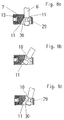
- the fold-side not shown Closing elements for example by lifting the wing 3 overcome by force, so the wing 3 in the direction of departure open wide until the locking bar 6 according to FIG. 4c on a shoulder 29 the eyelet 24 of the counter-closing part 7 rests.
- the tear Tear screws 25 off and the intrusion detector 28 with the applied conductor breaks and can cause a switching pulse or a message to a downstream control of the alarm system drop.
- the springs 26 released during this movement, the are installed with bias, push the push element 20 in the direction of opening and prevent it from moving back.
- the locking bar 6 moves within the eyelet 24.
- FIGS. 6 and 6 7 Further versions of the counter-locking part 7 are shown in FIGS. 6 and 6 7 shown, the explanations in the design of the intrusion detector 28 differentiate.
- the plate-shaped Intrusion detector 28 replaced by a reed contact.
- the Board-shaped intrusion detector 28 is not in a slot 27 between arranged the counter-closing part 7 and the push element 20, but by means of screw elements 31 between the contact surfaces of the counter-closing part 7 and the thrust element 20 attached.
- the rod lock 5 can additionally with a signaling contact (not shown) are provided, the one switching pulse settles when wing 3 is closed.
- a signaling contact (not shown) are provided, the one switching pulse settles when wing 3 is closed.
- This can be of the type. that in the locking bar 6 a small, preferably round, permanent magnet, is introduced and in the counter-closing part 7 a hereby coordinated Reed switch is arranged, the switching pulse when covered generates and switches.
Landscapes
- Engineering & Computer Science (AREA)
- Mechanical Engineering (AREA)
- Burglar Alarm Systems (AREA)
- Pens And Brushes (AREA)
- Catching Or Destruction (AREA)
- Mechanical Pencils And Projecting And Retracting Systems Therefor, And Multi-System Writing Instruments (AREA)
- Soil Working Implements (AREA)
- Gates (AREA)
- Patch Boards (AREA)
- Wing Frames And Configurations (AREA)
- Lock And Its Accessories (AREA)
Applications Claiming Priority (2)
| Application Number | Priority Date | Filing Date | Title |
|---|---|---|---|
| DE19943214 | 1999-09-09 | ||
| DE19943214A DE19943214C2 (de) | 1999-09-09 | 1999-09-09 | Stangenverriegelung für Flügel von Fenstern oder Türen |
Publications (3)
| Publication Number | Publication Date |
|---|---|
| EP1083286A2 true EP1083286A2 (fr) | 2001-03-14 |
| EP1083286A3 EP1083286A3 (fr) | 2003-12-10 |
| EP1083286B1 EP1083286B1 (fr) | 2005-08-17 |
Family
ID=7921421
Family Applications (1)
| Application Number | Title | Priority Date | Filing Date |
|---|---|---|---|
| EP00118743A Expired - Lifetime EP1083286B1 (fr) | 1999-09-09 | 2000-08-30 | Dispositif de fermeture avec tige de verrouillage pour fenêtres, portes, ou similaires |
Country Status (3)
| Country | Link |
|---|---|
| EP (1) | EP1083286B1 (fr) |
| AT (1) | ATE302320T1 (fr) |
| DE (2) | DE19943214C2 (fr) |
Cited By (1)
| Publication number | Priority date | Publication date | Assignee | Title |
|---|---|---|---|---|
| WO2002103142A1 (fr) * | 2001-06-18 | 2002-12-27 | Giovanni Maria Laporta | Mecanisme de fermeture |
Citations (2)
| Publication number | Priority date | Publication date | Assignee | Title |
|---|---|---|---|---|
| DE3844627A1 (de) | 1988-10-10 | 1990-04-12 | Melchert Beschlaege | Mit verschlussmitteln ausgeruestetes fenster, tuer oder dergleichen |
| EP0779945B1 (fr) | 1994-09-10 | 1998-10-28 | Erich Matouschek | Dispositif de fermeture declenchant une alarme pour la zone de fermeture et/ou charniere d'une porte ou d'une fenetre a rendre sure |
Family Cites Families (5)
| Publication number | Priority date | Publication date | Assignee | Title |
|---|---|---|---|---|
| DE9005487U1 (de) * | 1990-05-14 | 1990-09-06 | Zarges Leichtbau Gmbh, 8120 Weilheim | Schrankwagen |
| DE29508225U1 (de) * | 1995-05-18 | 1995-08-17 | Siegenia-Frank Kg, 57074 Siegen | Fenster oder Tür mit Schließstücken |
| DE19528320A1 (de) * | 1995-08-02 | 1997-02-27 | Weidtmann Wilhelm Kg | Verschlußvorrichtung für Fenster, Türen o. dgl. |
| DE19605047C2 (de) * | 1995-11-28 | 1998-04-09 | Aubi Baubeschlaege Gmbh | Dreh-Kipp-Beschlag für Fenster, Türen oder dergleichen |
| ATE182953T1 (de) * | 1995-11-28 | 1999-08-15 | Aubi Baubeschlaege Gmbh | Dreh-kipp-beschlag für fenster, türen oder dergleichen |
-
1999
- 1999-09-09 DE DE19943214A patent/DE19943214C2/de not_active Expired - Fee Related
-
2000
- 2000-08-30 EP EP00118743A patent/EP1083286B1/fr not_active Expired - Lifetime
- 2000-08-30 DE DE50010955T patent/DE50010955D1/de not_active Expired - Fee Related
- 2000-08-30 AT AT00118743T patent/ATE302320T1/de not_active IP Right Cessation
Patent Citations (2)
| Publication number | Priority date | Publication date | Assignee | Title |
|---|---|---|---|---|
| DE3844627A1 (de) | 1988-10-10 | 1990-04-12 | Melchert Beschlaege | Mit verschlussmitteln ausgeruestetes fenster, tuer oder dergleichen |
| EP0779945B1 (fr) | 1994-09-10 | 1998-10-28 | Erich Matouschek | Dispositif de fermeture declenchant une alarme pour la zone de fermeture et/ou charniere d'une porte ou d'une fenetre a rendre sure |
Cited By (2)
| Publication number | Priority date | Publication date | Assignee | Title |
|---|---|---|---|---|
| WO2002103142A1 (fr) * | 2001-06-18 | 2002-12-27 | Giovanni Maria Laporta | Mecanisme de fermeture |
| GB2376712B (en) * | 2001-06-18 | 2005-06-01 | Laporta Giovanni | Closure mechanism |
Also Published As
| Publication number | Publication date |
|---|---|
| DE19943214C2 (de) | 2003-04-10 |
| EP1083286B1 (fr) | 2005-08-17 |
| DE50010955D1 (de) | 2005-09-22 |
| ATE302320T1 (de) | 2005-09-15 |
| DE19943214A1 (de) | 2001-03-22 |
| EP1083286A3 (fr) | 2003-12-10 |
Similar Documents
| Publication | Publication Date | Title |
|---|---|---|
| EP3622139B1 (fr) | Fenêtre ou porte à limitation d'ouverture en basculement anti-effraction | |
| EP3309333A1 (fr) | Système comprenant un châssis dormant destiné à loger un cadre de vantail | |
| DE10113847A1 (de) | Sicherungsvorrichtung | |
| EP0173987B1 (fr) | Serrure complémentaire pour portes avec système de fermeture de sécurité | |
| EP0433623B1 (fr) | Dispositif de verrouillage d'une fenêtre, d'une porte ou similaires | |
| EP0635612B1 (fr) | Dispositif de verrouillage pour porte | |
| EP2113624B1 (fr) | Dispositif de fixation de porte ou de fenêtre | |
| DE102017002647B4 (de) | Einbruchsicherung für mindestens einen Flügel eines Fensters oder einer Tür | |
| DE19521601C1 (de) | Fenster, Tür oder dergleichen | |
| EP0779945B1 (fr) | Dispositif de fermeture declenchant une alarme pour la zone de fermeture et/ou charniere d'une porte ou d'une fenetre a rendre sure | |
| EP1160398B1 (fr) | Serrure à commande électrique | |
| EP0761920B1 (fr) | Fenêtre/porte avec battant pivotant et/ou basculant | |
| EP0270951B1 (fr) | Poignée verrouillable de fenêtre | |
| EP3222801A1 (fr) | Verrou pour coffres-forts | |
| EP1083286B1 (fr) | Dispositif de fermeture avec tige de verrouillage pour fenêtres, portes, ou similaires | |
| EP3516135B1 (fr) | Ferrure | |
| EP0505887A1 (fr) | Dispositif de verrouillage pour une porte de sécurité | |
| DE10318707B4 (de) | Sicherheitseinrichtung | |
| EP0733761B1 (fr) | Cadre de battant | |
| EP3235988A1 (fr) | Système de fenêtre et/ou système de porte | |
| EP0380059A2 (fr) | Verrouillage du coin d'une porte ou fenêtre | |
| DE20009716U1 (de) | Sicherheitsschloß zur Verwendung in sicherheitsrelevanten Einrichtungen | |
| DE19507481C1 (de) | Abschließbarer Fenstergriff | |
| DE19942563A1 (de) | Einbruchsicherung mit Befestigungsknopf | |
| EP3626920A1 (fr) | Serrure à pêne dormant |
Legal Events
| Date | Code | Title | Description |
|---|---|---|---|
| PUAI | Public reference made under article 153(3) epc to a published international application that has entered the european phase |
Free format text: ORIGINAL CODE: 0009012 |
|
| AK | Designated contracting states |
Kind code of ref document: A2 Designated state(s): AT BE CH CY DE DK ES FI FR GB GR IE IT LI LU MC NL PT SE |
|
| AX | Request for extension of the european patent |
Free format text: AL;LT;LV;MK;RO;SI |
|
| PUAL | Search report despatched |
Free format text: ORIGINAL CODE: 0009013 |
|
| AK | Designated contracting states |
Kind code of ref document: A3 Designated state(s): AT BE CH CY DE DK ES FI FR GB GR IE IT LI LU MC NL PT SE |
|
| AX | Request for extension of the european patent |
Extension state: AL LT LV MK RO SI |
|
| RIC1 | Information provided on ipc code assigned before grant |
Ipc: 7E 05B 63/24 B Ipc: 7E 05B 15/02 B Ipc: 7E 05C 9/18 A Ipc: 7E 05B 63/12 B Ipc: 7E 05D 15/52 B |
|
| 17P | Request for examination filed |
Effective date: 20040611 |
|
| AKX | Designation fees paid |
Designated state(s): AT BE CH CY DE DK ES FI FR GB GR IE IT LI LU MC NL PT SE |
|
| GRAP | Despatch of communication of intention to grant a patent |
Free format text: ORIGINAL CODE: EPIDOSNIGR1 |
|
| GRAS | Grant fee paid |
Free format text: ORIGINAL CODE: EPIDOSNIGR3 |
|
| GRAA | (expected) grant |
Free format text: ORIGINAL CODE: 0009210 |
|
| AK | Designated contracting states |
Kind code of ref document: B1 Designated state(s): AT BE CH CY DE DK ES FI FR GB GR IE IT LI LU MC NL PT SE |
|
| PG25 | Lapsed in a contracting state [announced via postgrant information from national office to epo] |
Ref country code: IT Free format text: LAPSE BECAUSE OF FAILURE TO SUBMIT A TRANSLATION OF THE DESCRIPTION OR TO PAY THE FEE WITHIN THE PRESCRIBED TIME-LIMIT;WARNING: LAPSES OF ITALIAN PATENTS WITH EFFECTIVE DATE BEFORE 2007 MAY HAVE OCCURRED AT ANY TIME BEFORE 2007. THE CORRECT EFFECTIVE DATE MAY BE DIFFERENT FROM THE ONE RECORDED. Effective date: 20050817 Ref country code: ES Free format text: LAPSE BECAUSE OF FAILURE TO SUBMIT A TRANSLATION OF THE DESCRIPTION OR TO PAY THE FEE WITHIN THE PRESCRIBED TIME-LIMIT Effective date: 20050817 Ref country code: IE Free format text: LAPSE BECAUSE OF FAILURE TO SUBMIT A TRANSLATION OF THE DESCRIPTION OR TO PAY THE FEE WITHIN THE PRESCRIBED TIME-LIMIT Effective date: 20050817 Ref country code: GB Free format text: LAPSE BECAUSE OF FAILURE TO SUBMIT A TRANSLATION OF THE DESCRIPTION OR TO PAY THE FEE WITHIN THE PRESCRIBED TIME-LIMIT Effective date: 20050817 Ref country code: FI Free format text: LAPSE BECAUSE OF FAILURE TO SUBMIT A TRANSLATION OF THE DESCRIPTION OR TO PAY THE FEE WITHIN THE PRESCRIBED TIME-LIMIT Effective date: 20050817 Ref country code: NL Free format text: LAPSE BECAUSE OF FAILURE TO SUBMIT A TRANSLATION OF THE DESCRIPTION OR TO PAY THE FEE WITHIN THE PRESCRIBED TIME-LIMIT Effective date: 20050817 |
|
| REG | Reference to a national code |
Ref country code: GB Ref legal event code: FG4D Free format text: NOT ENGLISH |
|
| PG25 | Lapsed in a contracting state [announced via postgrant information from national office to epo] |
Ref country code: CY Free format text: LAPSE BECAUSE OF FAILURE TO SUBMIT A TRANSLATION OF THE DESCRIPTION OR TO PAY THE FEE WITHIN THE PRESCRIBED TIME-LIMIT Effective date: 20050830 Ref country code: AT Free format text: LAPSE BECAUSE OF NON-PAYMENT OF DUE FEES Effective date: 20050830 |
|
| PG25 | Lapsed in a contracting state [announced via postgrant information from national office to epo] |
Ref country code: CH Free format text: LAPSE BECAUSE OF NON-PAYMENT OF DUE FEES Effective date: 20050831 Ref country code: LI Free format text: LAPSE BECAUSE OF NON-PAYMENT OF DUE FEES Effective date: 20050831 Ref country code: BE Free format text: LAPSE BECAUSE OF NON-PAYMENT OF DUE FEES Effective date: 20050831 Ref country code: MC Free format text: LAPSE BECAUSE OF NON-PAYMENT OF DUE FEES Effective date: 20050831 |
|
| REG | Reference to a national code |
Ref country code: CH Ref legal event code: EP |
|
| REG | Reference to a national code |
Ref country code: IE Ref legal event code: FG4D Free format text: LANGUAGE OF EP DOCUMENT: GERMAN |
|
| REF | Corresponds to: |
Ref document number: 50010955 Country of ref document: DE Date of ref document: 20050922 Kind code of ref document: P |
|
| PG25 | Lapsed in a contracting state [announced via postgrant information from national office to epo] |
Ref country code: LU Free format text: LAPSE BECAUSE OF NON-PAYMENT OF DUE FEES Effective date: 20051017 |
|
| PG25 | Lapsed in a contracting state [announced via postgrant information from national office to epo] |
Ref country code: SE Free format text: LAPSE BECAUSE OF FAILURE TO SUBMIT A TRANSLATION OF THE DESCRIPTION OR TO PAY THE FEE WITHIN THE PRESCRIBED TIME-LIMIT Effective date: 20051117 Ref country code: DK Free format text: LAPSE BECAUSE OF FAILURE TO SUBMIT A TRANSLATION OF THE DESCRIPTION OR TO PAY THE FEE WITHIN THE PRESCRIBED TIME-LIMIT Effective date: 20051117 Ref country code: GR Free format text: LAPSE BECAUSE OF FAILURE TO SUBMIT A TRANSLATION OF THE DESCRIPTION OR TO PAY THE FEE WITHIN THE PRESCRIBED TIME-LIMIT Effective date: 20051117 |
|
| PG25 | Lapsed in a contracting state [announced via postgrant information from national office to epo] |
Ref country code: PT Free format text: LAPSE BECAUSE OF FAILURE TO SUBMIT A TRANSLATION OF THE DESCRIPTION OR TO PAY THE FEE WITHIN THE PRESCRIBED TIME-LIMIT Effective date: 20060117 |
|
| NLV1 | Nl: lapsed or annulled due to failure to fulfill the requirements of art. 29p and 29m of the patents act | ||
| PG25 | Lapsed in a contracting state [announced via postgrant information from national office to epo] |
Ref country code: DE Free format text: LAPSE BECAUSE OF NON-PAYMENT OF DUE FEES Effective date: 20060301 |
|
| GBV | Gb: ep patent (uk) treated as always having been void in accordance with gb section 77(7)/1977 [no translation filed] |
Effective date: 20050817 |
|
| REG | Reference to a national code |
Ref country code: IE Ref legal event code: FD4D |
|
| REG | Reference to a national code |
Ref country code: CH Ref legal event code: PL |
|
| PLBE | No opposition filed within time limit |
Free format text: ORIGINAL CODE: 0009261 |
|
| STAA | Information on the status of an ep patent application or granted ep patent |
Free format text: STATUS: NO OPPOSITION FILED WITHIN TIME LIMIT |
|
| 26N | No opposition filed |
Effective date: 20060518 |
|
| PG25 | Lapsed in a contracting state [announced via postgrant information from national office to epo] |
Ref country code: FR Free format text: LAPSE BECAUSE OF FAILURE TO SUBMIT A TRANSLATION OF THE DESCRIPTION OR TO PAY THE FEE WITHIN THE PRESCRIBED TIME-LIMIT Effective date: 20060818 |
|
| EN | Fr: translation not filed | ||
| BERE | Be: lapsed |
Owner name: DORMA G.M.B.H. + CO. KG Effective date: 20050831 |
|
| PG25 | Lapsed in a contracting state [announced via postgrant information from national office to epo] |
Ref country code: FR Free format text: LAPSE BECAUSE OF FAILURE TO SUBMIT A TRANSLATION OF THE DESCRIPTION OR TO PAY THE FEE WITHIN THE PRESCRIBED TIME-LIMIT Effective date: 20050831 |
|
| PG25 | Lapsed in a contracting state [announced via postgrant information from national office to epo] |
Ref country code: FR Free format text: LAPSE BECAUSE OF FAILURE TO SUBMIT A TRANSLATION OF THE DESCRIPTION OR TO PAY THE FEE WITHIN THE PRESCRIBED TIME-LIMIT Effective date: 20050817 |