EP1085178A1 - Auspuffteil sowie verfahren zu seiner herstellung - Google Patents
Auspuffteil sowie verfahren zu seiner herstellung Download PDFInfo
- Publication number
- EP1085178A1 EP1085178A1 EP99921259A EP99921259A EP1085178A1 EP 1085178 A1 EP1085178 A1 EP 1085178A1 EP 99921259 A EP99921259 A EP 99921259A EP 99921259 A EP99921259 A EP 99921259A EP 1085178 A1 EP1085178 A1 EP 1085178A1
- Authority
- EP
- European Patent Office
- Prior art keywords
- inner pipe
- pipe
- portions
- reduced diameter
- end portions
- Prior art date
- Legal status (The legal status is an assumption and is not a legal conclusion. Google has not performed a legal analysis and makes no representation as to the accuracy of the status listed.)
- Withdrawn
Links
Images



Classifications
-
- F—MECHANICAL ENGINEERING; LIGHTING; HEATING; WEAPONS; BLASTING
- F01—MACHINES OR ENGINES IN GENERAL; ENGINE PLANTS IN GENERAL; STEAM ENGINES
- F01N—GAS-FLOW SILENCERS OR EXHAUST APPARATUS FOR MACHINES OR ENGINES IN GENERAL; GAS-FLOW SILENCERS OR EXHAUST APPARATUS FOR INTERNAL-COMBUSTION ENGINES
- F01N3/00—Exhaust or silencing apparatus having means for purifying, rendering innocuous, or otherwise treating exhaust
- F01N3/08—Exhaust or silencing apparatus having means for purifying, rendering innocuous, or otherwise treating exhaust for rendering innocuous
- F01N3/10—Exhaust or silencing apparatus having means for purifying, rendering innocuous, or otherwise treating exhaust for rendering innocuous by thermal or catalytic conversion of noxious components of exhaust
- F01N3/24—Exhaust or silencing apparatus having means for purifying, rendering innocuous, or otherwise treating exhaust for rendering innocuous by thermal or catalytic conversion of noxious components of exhaust characterised by constructional aspects of converting apparatus
- F01N3/28—Construction of catalytic reactors
- F01N3/2839—Arrangements for mounting catalyst support in housing, e.g. with means for compensating thermal expansion or vibration
- F01N3/2853—Arrangements for mounting catalyst support in housing, e.g. with means for compensating thermal expansion or vibration using mats or gaskets between catalyst body and housing
-
- B—PERFORMING OPERATIONS; TRANSPORTING
- B21—MECHANICAL METAL-WORKING WITHOUT ESSENTIALLY REMOVING MATERIAL; PUNCHING METAL
- B21D—WORKING OR PROCESSING OF SHEET METAL OR METAL TUBES, RODS OR PROFILES WITHOUT ESSENTIALLY REMOVING MATERIAL; PUNCHING METAL
- B21D22/00—Shaping without cutting, by stamping, spinning, or deep-drawing
- B21D22/14—Spinning
- B21D22/16—Spinning over shaping mandrels or formers
-
- B—PERFORMING OPERATIONS; TRANSPORTING
- B21—MECHANICAL METAL-WORKING WITHOUT ESSENTIALLY REMOVING MATERIAL; PUNCHING METAL
- B21D—WORKING OR PROCESSING OF SHEET METAL OR METAL TUBES, RODS OR PROFILES WITHOUT ESSENTIALLY REMOVING MATERIAL; PUNCHING METAL
- B21D39/00—Application of procedures in order to connect objects or parts, e.g. coating with sheet metal otherwise than by plating; Tube expanders
- B21D39/04—Application of procedures in order to connect objects or parts, e.g. coating with sheet metal otherwise than by plating; Tube expanders of tubes with tubes; of tubes with rods
-
- B—PERFORMING OPERATIONS; TRANSPORTING
- B21—MECHANICAL METAL-WORKING WITHOUT ESSENTIALLY REMOVING MATERIAL; PUNCHING METAL
- B21D—WORKING OR PROCESSING OF SHEET METAL OR METAL TUBES, RODS OR PROFILES WITHOUT ESSENTIALLY REMOVING MATERIAL; PUNCHING METAL
- B21D41/00—Application of procedures in order to alter the diameter of tube ends
- B21D41/04—Reducing; Closing
- B21D41/045—Closing
-
- F—MECHANICAL ENGINEERING; LIGHTING; HEATING; WEAPONS; BLASTING
- F01—MACHINES OR ENGINES IN GENERAL; ENGINE PLANTS IN GENERAL; STEAM ENGINES
- F01N—GAS-FLOW SILENCERS OR EXHAUST APPARATUS FOR MACHINES OR ENGINES IN GENERAL; GAS-FLOW SILENCERS OR EXHAUST APPARATUS FOR INTERNAL-COMBUSTION ENGINES
- F01N3/00—Exhaust or silencing apparatus having means for purifying, rendering innocuous, or otherwise treating exhaust
- F01N3/08—Exhaust or silencing apparatus having means for purifying, rendering innocuous, or otherwise treating exhaust for rendering innocuous
- F01N3/10—Exhaust or silencing apparatus having means for purifying, rendering innocuous, or otherwise treating exhaust for rendering innocuous by thermal or catalytic conversion of noxious components of exhaust
- F01N3/24—Exhaust or silencing apparatus having means for purifying, rendering innocuous, or otherwise treating exhaust for rendering innocuous by thermal or catalytic conversion of noxious components of exhaust characterised by constructional aspects of converting apparatus
- F01N3/28—Construction of catalytic reactors
-
- F—MECHANICAL ENGINEERING; LIGHTING; HEATING; WEAPONS; BLASTING
- F01—MACHINES OR ENGINES IN GENERAL; ENGINE PLANTS IN GENERAL; STEAM ENGINES
- F01N—GAS-FLOW SILENCERS OR EXHAUST APPARATUS FOR MACHINES OR ENGINES IN GENERAL; GAS-FLOW SILENCERS OR EXHAUST APPARATUS FOR INTERNAL-COMBUSTION ENGINES
- F01N2450/00—Methods or apparatus for fitting, inserting or repairing different elements
- F01N2450/02—Fitting monolithic blocks into the housing
Definitions
- the present invention relates to parts in an exhaust system and a method of producing the parts.
- a heat insulating double structure in which an inner pipe having both end portions reduced so as to be formed in a taper shape and an outer pipe having both end portions reduced so as to be formed in a taper shape are arranged with an air gap therebetween.
- a catalyst converter in which a metal outer pipe 105 having taper-like reduced diameter portions 104 at both end portions is arranged on an outer periphery of a metal inner pipe 103 containing a catalyst carrier 101 and having taper-like reduced diameter portions 102 at both end portions so as to provide a gap 106 between the inner pipe 103 and the outer pipe 105.
- a light off characteristic of a catalyst is improved by a heat insulating effect of the gap 106 and an exhaust gas purifying performance is improved.
- a catalyst converter having the structure mentioned above is, for example, disclosed in Japanese Patent Unexamined Publication No. 6-101465.
- a method of producing the double pipe mentioned above there can be employed a general producing method comprising the steps of forming outer pipes having a shape reduced at both end portions in a hollow shape and in a double-split manner in an axial direction of the pipe, arranging them on an outside of a previously formed inner pipe while holding a gap between the inner pipe and the outer pipes, and bonding the outer pipes formed in the double-split manner to each other by a welding or the like.
- a cost is increased due to pressing dies, a welding process or the like.
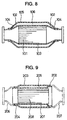
- a catalyst converter structured such that a large-diameter portion 202 is formed in one end portion of the inner pipe 201, a small-diameter portion 204 is formed in an end portion of the outer pipe 203 opposing to the large-diameter portion 202 of the inner pipe, and the inner and outer pipes 201 and 203 are fitted to each other so as to bring the large-diameter portion 202 and the outer pipe 203 into contact with each other and bring the small-diameter portion 204 and the inner pipe 201 into contact with each other, thereby holding the gap 205 between the inner and outer pipes 201 and 203.
- This structure is disclosed, for example, in Japanese Patent Unexamined Publication No. 9-108576.
- taper-like diffusers 206 and 207 are provided in both ends of the structure obtained by combining the inner and outer pipes, in the structure shown in Fig. 9.
- the gap 205 can be formed only between the inner pipe 201 and the outer pipe 203 where the catalyst carrier 208 exists, and no gap can be formed in the taper portions (diffuser portions) of both end portions. Further, since the inner and outer pipes 201 and 203 are bonded in the portion near the catalyst carrier 208, a heat transmission is performed in the portion near the catalyst carrier.
- the catalyst converter shown in Fig. 9 has a low heat insulating effect and an expected heat insulating effect can not be obtained, so that it is difficult to reduce a time required for activation of the catalyst.
- an object of the present invention is to provide parts in an exhaust system in which a gap is formed in series to both of taper-like reduced diameter portions of inner and outer pipes as shown in Fig. 8 mentioned above, and a method of easily and inexpensively producing the parts in the exhaust system.
- parts in an exhaust system comprising:
- the structure may be made such that a heat insulating member or a damper member is interposed in at least a part within the gap.
- the structure may be made such that a heat insulating member or a damper member is interposed in at least a part between the inner pipe and the outer pipe at said step of fitting the outer pipe.
- FIGs. 1A, 1B and 2A to 2D show a first embodiment in which the present invention is applied to a catalyst converter.
- FIGs. 1A and 1B are vertical cross sectional views of the catalyst converter in accordance with the present invention.
- a center portion 1a of a metal inner pipe 1 is formed in a circular pipe shape, and a catalyst carrier 2 is inserted and received within the center portion 1a.
- Substantially taper-like reduced diameter portions (cone portions) 1b and 1c in which a pipe wall of the inner pipe 1 is inward deformed are integrally formed in both end portions of the inner pipe 1, and cylindrical connection portions 1d and 1e are integrally formed in front portions of both of the reduced diameter portions 1b and 1c.
- An outer pipe 3 having a cylindrical center portion 3a with a diameter larger than the center portion 1a of the inner pipe 1 is fitted on an outer side of the inner pipe 1, and a center gap 4 is formed between both of the center portions 1a and 3a.
- Both end portions in the outer pipe 3, that is, the portions corresponding to the outer peripheries of the reduced diameter portions 1b and 1c in the inner pipe 1 are integrally formed in such a manner as to construct inward deformed substantially taper-like reduced diameter portions (cone portions) 3b and 3c, and cylindrical connection portions 3d and 3e reduced so as to be close attached to the outer periphery of the connection portions 1d and 1e of the inner pipe 1 are integrally formed in front portions of both of the reduced diameter portions 3b and 3c.
- Tapered side gaps 4a and 4a formed so that an interval of the gap is made narrower as moving toward the front end portion are formed between the taper-like reduced diameter portions 1b and 1c of the inner pipe 1 and the taper-like reduced diameter portions 3b and 3c of the outer pipe 3, and both of the side gaps 4a and 4a are formed in series with the center gap 4.
- a heating insulating member 5 is received within the center gap 4, and the heat insulating member 5 is held between the inner and outer pipes 1 and 3.
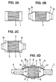
- the catalyst converter 2 is inserted into the cylindrical inner pipe 1 in which both end portions are open, from one open end, as shown in Fig. 2A.
- a catalyst holding mat made of ceramics is inserted between the inner pipe 1 and the catalyst carrier 2.
- the taper-like reduced diameter portions 1b and 1c are formed by reducing both end portions of the inner pipe 1 in accordance with a reducing process as shown in Fig. 2B. Further, the cylindrical connection portions 1d and 1e are formed in the front portion thereof.
- the cylindrical outer pipe 3 in which a diameter thereof is larger than the outer diameter of the inner pipe 1 and both end portions thereof is open is fitted onto the outer periphery of the inner pipe 1 as shown in Fig. 2C.
- the heat insulating member (the heat insulating mat) 5 is interposed between the inner pipe 1 and the outer pipe 3 as shown in Fig. 2C if necessary.
- both end portions of the outer pipe 3 are reduced so as to be plastically deformed by the spinning roller 9, whereby the taper-like reduced diameter portions 3b and 3c are formed.
- the taper-like reduced diameter portions 3b and 3c of the outer pipe 3 are formed so as to preciously keep the gap 4a with respect to the taper-like reduced diameter portions 1b and 1c of the inner pipe 1, and it is possible to dispose the bore portions along the bore portions of the inner pipe 1.
- both taper-like reduced diameter portions 3b and 3c in the outer pipe 3 are pressed by the spinning roller 9 so as to be pressed to the outer peripheral surfaces of the connection portions 1d and 1e in the inner pipe 1 and plastically deformed, and the inner and outer pipes 1 and 3 are integrally structured by connecting the pressed connection portions 3d and 3e to the connection portions 1d and 1e of the inner pipe 1.
- the side gap 4a is also provided in the taper-like reduced diameter portion corresponding to the cone portion, the side gap 4a is communicated with the center gap 4, and a contact portion between the inner and outer pipes 1 and 3, that is, a heat transmitting portion is placed at a position far apart from the catalyst carrier 2 in an axial direction. Accordingly, a heat insulating characteristic due to the gaps 4 and 4a is made higher than that of the structure shown in Fig. 9, and a desired heat insulating effect can be obtained. Further, a heat insulating effect can be further increased by interposing the adiabatic member 5.
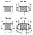
- Figs. 3A to 3D show an embodiment structured such that a damper member, for example, a wire mesh 10 made of a metal small wire is interposed between the inner and outer pipes 1 and 3 at a position corresponding to both axial end portions of the catalyst carrier 2, in place of the heat insulating member (the heat insulating mat) 5 mentioned above, as shown in Fig. 3C.
- a damper member for example, a wire mesh 10 made of a metal small wire is interposed between the inner and outer pipes 1 and 3 at a position corresponding to both axial end portions of the catalyst carrier 2, in place of the heat insulating member (the heat insulating mat) 5 mentioned above, as shown in Fig. 3C.
- the other structures and producing methods are the same as those mentioned above.
- the damper member 10 can prevents the inner pipe 1 and the outer pipe 3 from being brought into contact with each other due to vibration.
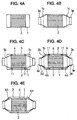
- Figs. 4A to 4E show an embodiment structured such that a member evanished due to heating, for example, a supporting member 11 made of a paper or the like is interposed in place of the damper member 10.
- a member evanished due to heating for example, a supporting member 11 made of a paper or the like is interposed in place of the damper member 10.
- the other structures and producing methods are the same as those mentioned above.
- the outer pipe 1 can be held at the position having a predetermined gap by the supporting member 11 at the production time explained in Figs. 2A to 2D mentioned above, and the supporting member 11 is carbonized and evanished by heating after production, so that the gap with which the central gap 4 and both side gaps 4a are communicated are formed as shown in Fig. 4E.
- Fig. 5 shows an embodiment structured such that a damper member, for example a wire mesh 12 made of a metal small wire is interposed between the connection portions 1d and 3d, and 1e and 3e (only the 1e and 3e side is shown in Fig. 5). That is, a step portion 13 due to drawing is formed at a position shown in Fig. 5 of the connection portions 1d and 1e of the inner pipe 1, a step portion 14 due to drawing is formed at a position shown in Fig. 5 of the connection portions 3d and 3e of the outer pipe 3, and the wire mesh 12 is interposed between the step portions 13 and 14.
- a damper member for example a wire mesh 12 made of a metal small wire is interposed between the connection portions 1d and 3d, and 1e and 3e (only the 1e and 3e side is shown in Fig. 5). That is, a step portion 13 due to drawing is formed at a position shown in Fig. 5 of the connection portions 1d and 1e of the inner pipe 1, a step portion 14 due to drawing
- both end portions of the outer pipe 3 are reduced in accordance with the spinning process after the outer pipe is fitted on the inner pipe.
- the structure may be made such that one end portion of the outer pipe 3 is previously reduced in accordance with the spinning process, the inner pipe 1 having reduced both end portions is inserted from another end portion which is not reduced, whereby the outer pipe is fitted on the inner pipe, and thereafter, another end portion of the outer pipe 3 is reduced in accordance with the spinning process.
- Figs. 6A to 6C show an embodiment for producing parts in an exhaust system in which, with respect to an axis X1 of the connection portions 1d and 3d of one end portion A in the inner pipe 1 and the outer pipe 3, an axis X2 of the connection portions 1e and 3e of another end portion B is eccentric at a predetermined amount.
- the taper-like reduced diameter portions 1b and 1c and the cylindrical connection portions 1d and 1e are continuously reduced and formed in both end portions of the center portion 1a in the inner pipe, and there is formed the inner pipe 1 structured such that the axis X2 of the taper-like reduced diameter portion 1c and the connection portion 1e in the another end portion is eccentric at a predetermined amount OF with respect to the axis X1 of the taper-like reduced diameter portion 1b and the connection portion 1d in the one end portion A.
- the outer pipe 1 which is not reduced is supported by the supporting device on the outer periphery of the inner pipe 1 supported by the supporting device so as not to rotate, in such a manner as not to rotate with the predetermined gap 4 therebetween, so as to fit the outer pipe on the inner pipe.
- the spinning roller 9 is structured such that a plurality of spinning rollers 9 (two spinning rollers are shown in the illustrated embodiment) are arranged in a peripheral direction around the axis X1, and each of the spinning rollers 9 can rotate on its own axis, revolves around the axis X1 and moves in a direction perpendicular to the axis X1 and the axial direction.
- the spinning roller 9 revolving around the axis X1 is moved in a centripetal direction and the direction of the axis X1 so as to form the taper-like reduced diameter portion 3b and the cylindrical connection portion 3d fitted to each other with a predetermined gap 4a on the outer periphery of the taper-like reduced diameter portion 1b and the connection portion 1d as shown in Fig. 6A.
- the reducing process at a predetermined amount as shown in Fig. 6B is performed by coinciding the axis X2 of the connection portion 1e of the inner pipe 1 in the another end portion B with the axis of revolution of the spinning roller 9 and moving the spinning roller 9 revolving around the outer peripheral surface of the another end portion B of the outer pipe 3 in the centripetal direction and the direction of the axis X2.
- the taper-like reduced diameter portion 3c of the another end portion B of the outer pipe 3 is finally reduced and formed in the outer peripheral portion of the taper-like reduced diameter portion 1c of the inner pipe 1 with the predetermined gap 4a and the connection portion 3e is reduced and formed in the outer peripheral portion of the connection portion 1e of the inner pipe 1 with the predetermined gap as shown in Fig. 6C by repeating the steps at one or more times.
- Figs. 7A to 7C show an embodiment for producing parts in an exhaust system in which, with respect to an axis X1 of the connection portions 1d and 3d of one end portion A in the inner pipe 1 and the outer pipe 3 in the parts in the exhaust system shown in Figs 6A to 6C, an axis X2 of the connection portions 1e and 3e is bent at a predetermined angle.
- the taper-like reduced diameter portions 1b and 1c and the cylindrical connection portions 1d and 1e are continuously formed in both end portions of the center portion 1a in the inner pipe, and there is formed the inner pipe 1 structured such that the axis X2 of the taper-like reduced diameter portion 1c and the connection portion 1e in the another end portion is oblique at a predetermined angle ⁇ with respect to the axis X1 of the taper-like reduced diameter portion 1b and the connection portion 1d in the one end portion A.
- the outer pipe 3 into which the inner pipe 1 is fitted is set so that the axis X1 thereof is oblique at a predetermined angle ⁇ 2 with respect to an axis X3 of revolution of the spinning roller 9, and a reducing process is performed at a predetermined amount, as shown in Fig. 7B, by moving the spinning roller 9 revolving around the axis X3 on the outer peripheral surface of the another end portion B of the outer pipe 3 in the centripetal direction and the direction of the axis X3.
- the inner and outer pipes 1 and 3 are further rotated around a center portion O thereof from a state in Fig. 7B, and as shown in Fig. 7C, the spinning process is performed by coinciding the axis X2 of the connection portion 1e of the another end portion B in the inner pipe 1 with the axis X3 of revolution of the spinning roller 9 as shown in Fig. 7C, and the taper-like reduced diameter portion 3c of the another end portion B in the outer pipe 3 is reduced and formed in the outer peripheral portion of the taper-like reduced diameter portion 1c in the inner pipe 1 with a predetermined gap 4a as shown in Fig. 7C, and the connection portion 3e is reduced and formed in the outer peripheral portion of the connection portion 1e in the inner pipe 1 with a predetermined gap.
- the compressed both end portions of the formed inner pipe 1 and outer pipe 3 are connected to the inner and outer pipes such as a connected double exhaust pipe or the like, whereby the gaps 4 and 4a between the inner pipe 1 and the outer pipe 3 can be kept.
- connection portions 3d and 3e of the outer pipe 3 may be bonded to the connection portions 1d and 1e of the inner pipe 1.
- the structure is made such that the portions to be reduced in both end portions of the outer pipe are formed by reducing them in accordance with the spinning process, it is possible to easily form the parts in the exhaust system in which both end portions are reduced to the outer periphery of the inner pipe in which both end portions are reduced so as to bond the reduced diameter ends of the outer pipe to the reduced diameter ends of the inner pipe or to be apart the former from the latter and the gap is formed between the inner pipe and the outer pipe all along both reduced diameter portions of the outer pipe. Further, it is possible to integrally form the outer pipe with no joints not only in a whole length in the axial direction thereof but also in the peripheral direction.
- the inner pipe and the outer pipe can be bonded to each other by a plastic deformation in accordance with the spinning process, the inner pipe and the outer pipe can be connected without using a welding process or a pressing process.
- a heat insulating performance can be improved by interposing the heat insulating member in the gap between the inner and outer pipes. Further, it is possible to prevent the inner pipe and the outer pipe from being brought into contact with each other due to vibration by interposing the damper member.
- the producing method including the step of fitting the outer pipe on the outer side of the inner pipe containing the catalyst carrier in the center portion and having the substantially taper-like reduced diameter portions formed in both end portions of the center portion while holding the gap, and the step of applying the spinning process in such a manner as to have the gap between both end portions of the outer pipe and the reduced diameter portion in the inner pipe so as to reduce both end portions of the outer pipe in the substantially taper shape, the parts in the exhaust system mentioned above can be easily produced.
- the parts in the exhaust system in such a manner as to interpose one of the heat insulating member and the damper member in at least a part between the inner pipe and the outer pipe at a time of fitting the outer pipe on the inner pipe, it is possible to easily produce the parts in the exhaust system in which the heat insulating member or the damper member is interposed within the gap.
Landscapes
- Engineering & Computer Science (AREA)
- Chemical & Material Sciences (AREA)
- Chemical Kinetics & Catalysis (AREA)
- Mechanical Engineering (AREA)
- Health & Medical Sciences (AREA)
- Toxicology (AREA)
- Combustion & Propulsion (AREA)
- General Engineering & Computer Science (AREA)
- Exhaust Gas After Treatment (AREA)
- Exhaust Silencers (AREA)
Applications Claiming Priority (3)
| Application Number | Priority Date | Filing Date | Title |
|---|---|---|---|
| JP14676098 | 1998-05-28 | ||
| JP10146760A JP2957163B1 (ja) | 1998-05-28 | 1998-05-28 | 排気系部品とその製造方法 |
| PCT/JP1999/002739 WO1999061764A1 (en) | 1998-05-28 | 1999-05-25 | Emission system part and method of manufacturing the part |
Publications (2)
| Publication Number | Publication Date |
|---|---|
| EP1085178A1 true EP1085178A1 (de) | 2001-03-21 |
| EP1085178A4 EP1085178A4 (de) | 2009-05-20 |
Family
ID=15414957
Family Applications (1)
| Application Number | Title | Priority Date | Filing Date |
|---|---|---|---|
| EP99921259A Withdrawn EP1085178A4 (de) | 1998-05-28 | 1999-05-25 | Auspuffteil sowie verfahren zu seiner herstellung |
Country Status (5)
| Country | Link |
|---|---|
| US (1) | US6942838B1 (de) |
| EP (1) | EP1085178A4 (de) |
| JP (1) | JP2957163B1 (de) |
| KR (1) | KR100395741B1 (de) |
| WO (1) | WO1999061764A1 (de) |
Cited By (2)
| Publication number | Priority date | Publication date | Assignee | Title |
|---|---|---|---|---|
| WO2001092696A3 (en) * | 2000-06-02 | 2002-03-14 | Toyota Motor Co Ltd | Hollow product, fluid processing system and joining method of hollow members |
| CN100434660C (zh) * | 2003-05-13 | 2008-11-19 | 赫斯工程股份有限公司 | 制造催化式排气净化器的方法和装置 |
Families Citing this family (19)
| Publication number | Priority date | Publication date | Assignee | Title |
|---|---|---|---|---|
| JP2957176B1 (ja) * | 1998-09-24 | 1999-10-04 | 株式会社三五 | 二重構造容器の製造方法 |
| US6591498B2 (en) | 1999-08-03 | 2003-07-15 | Sango Co., Ltd. | Method of producing a catalytic converter |
| US6381843B1 (en) * | 1999-08-03 | 2002-05-07 | Sango Co., Ltd. | Method of producing a catalytic converter |
| NL1017010C2 (nl) * | 2000-12-29 | 2002-07-02 | Johan Massue | Werkwijze en inrichting voor het vervormen van een hol werkstuk. |
| JP3738828B2 (ja) | 2001-01-19 | 2006-01-25 | トヨタ自動車株式会社 | 二重管構造中空部材、その製造方法、および二重管構造中空部材を使用した流体処理システム |
| JP2002227640A (ja) * | 2001-02-02 | 2002-08-14 | Sankei Kogyo Kk | 排気ガス浄化装置 |
| NL1020171C2 (nl) * | 2002-03-13 | 2003-09-16 | Johan Massee | Werkwijze en forceermachine voor het bewerken van een werkstuk. |
| SE527023C2 (sv) * | 2004-04-27 | 2005-12-06 | Koenigsegg Automotive Ab | Avgasrenare för förbränningsmotorer med förkatalysator, huvudkatalysator samt en förbiledningskanal |
| US7611561B2 (en) * | 2006-07-20 | 2009-11-03 | Benteler Automotive Corporation | Diesel exhaust filter construction |
| JP4501971B2 (ja) * | 2007-08-24 | 2010-07-14 | トヨタ自動車株式会社 | 排気浄化装置 |
| JP2009195941A (ja) * | 2008-02-21 | 2009-09-03 | Nisshin Steel Co Ltd | スピニング加工方法 |
| DE102009014435A1 (de) * | 2009-03-26 | 2010-10-14 | J. Eberspächer GmbH & Co. KG | Abgasbehandlungseinrichtung |
| JP2014134179A (ja) | 2013-01-11 | 2014-07-24 | Futaba Industrial Co Ltd | 触媒コンバータ |
| WO2017151965A1 (en) * | 2016-03-02 | 2017-09-08 | Watlow Electric Manufacturint Company | Heater element having targeted decreasing temperature resistance characteristics |
| CN106194349A (zh) * | 2016-07-07 | 2016-12-07 | 上海天纳克排气系统有限公司 | 催化器载体的封装方法及其后处理组件 |
| DE102016117746A1 (de) * | 2016-09-21 | 2018-03-22 | Eberspächer Exhaust Technology GmbH & Co. KG | Reaktionsmitteleingabeanordnung zur Eingabe von Reaktionsmittel in den Abgasstrom einer Brennkraftmaschine |
| US10436099B2 (en) | 2017-04-06 | 2019-10-08 | Tenneco Automotive Operating Company Inc. | Exhaust conduit hanger |
| US20180291794A1 (en) * | 2017-04-06 | 2018-10-11 | Tenneco Automotive Operating Company Inc. | Double Thin Wall Conduit Hanger |
| JP6932231B1 (ja) * | 2020-11-30 | 2021-09-08 | マレリ株式会社 | 排気処理装置 |
Family Cites Families (16)
| Publication number | Priority date | Publication date | Assignee | Title |
|---|---|---|---|---|
| JPS5738557B2 (de) * | 1973-04-11 | 1982-08-16 | ||
| GB1457931A (en) | 1973-03-10 | 1976-12-08 | Nippon Denso Co | High-temperature insulating structures |
| JPS5738557A (en) | 1980-08-21 | 1982-03-03 | Tokyo Shibaura Electric Co | Incandescent lamp |
| JPS6012614U (ja) * | 1983-07-06 | 1985-01-28 | マツダ株式会社 | エンジンの排気ガス浄化装置 |
| JPS6061428U (ja) * | 1983-10-03 | 1985-04-30 | マツダ株式会社 | 触媒コンバ−タ |
| JPS6345533A (ja) | 1986-08-13 | 1988-02-26 | Hajime Honda | 表面張力測定素子 |
| JPS6411937A (en) | 1987-07-02 | 1989-01-17 | Sky Aluminium | Aluminum alloy rolled plate for forming and its production |
| JPH06101465A (ja) | 1992-09-22 | 1994-04-12 | Nissan Motor Co Ltd | 2重管触媒コンバータ |
| JP3294036B2 (ja) | 1995-01-26 | 2002-06-17 | 日本碍子株式会社 | ハニカム触媒コンバータ |
| US5849251A (en) * | 1995-07-17 | 1998-12-15 | Timko; Mark | Catalytic converter for a tailpipe including apparatus for relieving back pressure |
| JP3585064B2 (ja) * | 1995-10-12 | 2004-11-04 | トヨタ自動車株式会社 | モノリス触媒コンバータ及びその製造方法 |
| JPH09108576A (ja) | 1995-10-16 | 1997-04-28 | Calsonic Corp | 触媒コンバータのメタル担体 |
| JP3571832B2 (ja) | 1995-12-08 | 2004-09-29 | 新日本製鐵株式会社 | メタル担体の製造方法 |
| US5849250A (en) * | 1997-02-03 | 1998-12-15 | Timko; Mark | Auxiliary catalytic converter having a back pressure relief device |
| US6935461B2 (en) * | 1998-08-18 | 2005-08-30 | Gregory M. Marocco | Exhaust sound and emission control systems |
| JP3738828B2 (ja) * | 2001-01-19 | 2006-01-25 | トヨタ自動車株式会社 | 二重管構造中空部材、その製造方法、および二重管構造中空部材を使用した流体処理システム |
-
1998
- 1998-05-28 JP JP10146760A patent/JP2957163B1/ja not_active Expired - Fee Related
-
1999
- 1999-05-25 KR KR10-2000-7013209A patent/KR100395741B1/ko not_active Expired - Fee Related
- 1999-05-25 US US09/701,255 patent/US6942838B1/en not_active Expired - Fee Related
- 1999-05-25 WO PCT/JP1999/002739 patent/WO1999061764A1/ja not_active Ceased
- 1999-05-25 EP EP99921259A patent/EP1085178A4/de not_active Withdrawn
Cited By (2)
| Publication number | Priority date | Publication date | Assignee | Title |
|---|---|---|---|---|
| WO2001092696A3 (en) * | 2000-06-02 | 2002-03-14 | Toyota Motor Co Ltd | Hollow product, fluid processing system and joining method of hollow members |
| CN100434660C (zh) * | 2003-05-13 | 2008-11-19 | 赫斯工程股份有限公司 | 制造催化式排气净化器的方法和装置 |
Also Published As
| Publication number | Publication date |
|---|---|
| WO1999061764A1 (en) | 1999-12-02 |
| JPH11336537A (ja) | 1999-12-07 |
| US6942838B1 (en) | 2005-09-13 |
| KR20010043791A (ko) | 2001-05-25 |
| KR100395741B1 (ko) | 2003-08-27 |
| JP2957163B1 (ja) | 1999-10-04 |
| EP1085178A4 (de) | 2009-05-20 |
Similar Documents
| Publication | Publication Date | Title |
|---|---|---|
| US6942838B1 (en) | Emission system part and method of manufacturing the part | |
| JP3585064B2 (ja) | モノリス触媒コンバータ及びその製造方法 | |
| US5937516A (en) | Method for spin forming articles | |
| US4519120A (en) | Process for manufacturing a cartridge for purifying exhaust gas | |
| US8857056B2 (en) | Method of manufacturing an exhaust gas carrying device and tool therefor | |
| US6010668A (en) | End cone assembly and method for catalytic converter | |
| EP0972915B1 (de) | Verfahren zur herstellung eines schalldämpfers | |
| JPS6254566B2 (de) | ||
| JP3401173B2 (ja) | 触媒コンバータの製造方法 | |
| JP3500109B2 (ja) | 排気ガス処理装置の製造方法 | |
| JP4278616B2 (ja) | サイレンサー用または触媒用のカバーの製造方法 | |
| JP3490947B2 (ja) | ガスの処理装置の製造方法 | |
| JPH1061424A (ja) | 消音器及びその製造方法 | |
| US20060219357A1 (en) | Pipe manufacturing method and inner pipe of double pipe | |
| JP2000088150A (ja) | 配管類の組立方法及び組立構造 | |
| JP2006000873A (ja) | 金属管の接合方法 | |
| JPH115265A (ja) | ハニカム本体、ハニカム本体の通路を閉じるための装置、ならびにハニカム本体を製造するためのプロセスおよび機器 | |
| JP2645809B2 (ja) | 排気管に接続されるシェルの端部部材とその製造方法 | |
| JP2813932B2 (ja) | メタルハニカム担体の製造方法 | |
| JPH10317941A (ja) | 自動車用マフラーの製造方法 | |
| JPH09155202A (ja) | メタル担体およびその製造方法 | |
| JP2003013734A (ja) | 排気系部品およびその製造方法 | |
| JP3302116B2 (ja) | メタル担体の製造方法 | |
| JPH04339531A (ja) | 多重排気管の製造方法 | |
| JP3694352B2 (ja) | 触媒担体の製造方法 |
Legal Events
| Date | Code | Title | Description |
|---|---|---|---|
| PUAI | Public reference made under article 153(3) epc to a published international application that has entered the european phase |
Free format text: ORIGINAL CODE: 0009012 |
|
| 17P | Request for examination filed |
Effective date: 20001127 |
|
| AK | Designated contracting states |
Kind code of ref document: A1 Designated state(s): DE FR GB IT |
|
| A4 | Supplementary search report drawn up and despatched |
Effective date: 20090421 |
|
| RIC1 | Information provided on ipc code assigned before grant |
Ipc: B21D 22/00 20060101ALI20090415BHEP Ipc: F01N 3/28 20060101AFI19991208BHEP |
|
| 17Q | First examination report despatched |
Effective date: 20090714 |
|
| R17C | First examination report despatched (corrected) |
Effective date: 20090805 |
|
| STAA | Information on the status of an ep patent application or granted ep patent |
Free format text: STATUS: THE APPLICATION IS DEEMED TO BE WITHDRAWN |
|
| 18D | Application deemed to be withdrawn |
Effective date: 20091216 |