EP1085533A1 - Filtre de mode commun - Google Patents
Filtre de mode commun Download PDFInfo
- Publication number
- EP1085533A1 EP1085533A1 EP00120477A EP00120477A EP1085533A1 EP 1085533 A1 EP1085533 A1 EP 1085533A1 EP 00120477 A EP00120477 A EP 00120477A EP 00120477 A EP00120477 A EP 00120477A EP 1085533 A1 EP1085533 A1 EP 1085533A1
- Authority
- EP
- European Patent Office
- Prior art keywords
- core
- drum
- winding
- common mode
- flanges
- Prior art date
- Legal status (The legal status is an assumption and is not a legal conclusion. Google has not performed a legal analysis and makes no representation as to the accuracy of the status listed.)
- Granted
Links
- 238000004804 winding Methods 0.000 claims abstract description 55
- 239000000853 adhesive Substances 0.000 claims abstract description 15
- 230000001070 adhesive effect Effects 0.000 claims abstract description 15
- 239000003795 chemical substances by application Substances 0.000 abstract description 2
- 238000005476 soldering Methods 0.000 description 8
- 229910000679 solder Inorganic materials 0.000 description 5
- 230000002411 adverse Effects 0.000 description 3
- 230000000694 effects Effects 0.000 description 3
- 239000004020 conductor Substances 0.000 description 2
- 238000010586 diagram Methods 0.000 description 2
- 238000007747 plating Methods 0.000 description 2
- 238000003466 welding Methods 0.000 description 2
- 238000010438 heat treatment Methods 0.000 description 1
- 239000000758 substrate Substances 0.000 description 1
- 229910000859 α-Fe Inorganic materials 0.000 description 1
Images


Classifications
-
- H—ELECTRICITY
- H01—ELECTRIC ELEMENTS
- H01F—MAGNETS; INDUCTANCES; TRANSFORMERS; SELECTION OF MATERIALS FOR THEIR MAGNETIC PROPERTIES
- H01F17/00—Fixed inductances of the signal type
- H01F17/04—Fixed inductances of the signal type with magnetic core
- H01F17/045—Fixed inductances of the signal type with magnetic core with core of cylindric geometry and coil wound along its longitudinal axis, i.e. rod or drum core
-
- H—ELECTRICITY
- H01—ELECTRIC ELEMENTS
- H01F—MAGNETS; INDUCTANCES; TRANSFORMERS; SELECTION OF MATERIALS FOR THEIR MAGNETIC PROPERTIES
- H01F27/00—Details of transformers or inductances, in general
- H01F27/02—Casings
-
- H—ELECTRICITY
- H01—ELECTRIC ELEMENTS
- H01F—MAGNETS; INDUCTANCES; TRANSFORMERS; SELECTION OF MATERIALS FOR THEIR MAGNETIC PROPERTIES
- H01F27/00—Details of transformers or inductances, in general
- H01F27/28—Coils; Windings; Conductive connections
- H01F27/29—Terminals; Tapping arrangements for signal inductances
- H01F27/292—Surface mounted devices
Definitions
- the present invention relates to a common mode filter which is mainly used for a small-sized electronic appliance, and more particularly to a common mode filter which can effectively deal with noises in a power source line which is small in size but requires a relatively large current or data line in a low-profiled appliance such as a digital vide camera, MD (mini disk) player, CD (compact disk) player, portable PC (personal computer), etc.
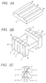
- Figs. 5B and 5C shows a chip inductor disclosed in JP-A-8-186028 in which a plate-like core 38 is combined with a drum-shaped core with flanges 36 at both ends and terminals 39a of a winding 39 are fixed to electrodes 40 attached to the flange 36 by soldering or like.
- the present invention intends to provide a common mode filter which is small in size but can be used for a relatively large current, can be easily recognized in its mounted state on a substrate and can be low-profiled.
- the common mode filter according to the present invention includes a drum-shaped core having flanges at both ends of a winding core around which a winding is wound and a plate-like core with both ends fixed to the flanges to form a closed path between itself and the drum-shaped core, in that concave portions are formed in at least one of facing potions of both cores to provide gaps between the flanges of the drum-shaped core and the plate-like core; and a plurality of electrodes each of which is successive over a upper surface, end surface and lower surface of each flange are provided at portions corresponding to the gaps in each of the flanges; and a plurality of windings are wound around the winding core, both ends of each of the plurality of windings being connected and secured to the electrodes on the upper surface of each of the flanges, respectively; and the drum-shaped core and the plate-like core are fixed to each other by an adhesive.
- the winding terminal is fixed to the electrode in such a manner that it is housed in a gap formed by the concave portion between the flange and plate-like core. Therefore, the winding terminal can be housed in the form of a round wiring. This contributes to provide a common mode filter which is small in size and can be used for a relatively large current. The winding terminal will not be broken since it is not required to be flattened. Further, since the winding terminal is housed in the gap formed by the concave portion, the height of the upper surface of the plate-like core can be suppressed, thus providing a low-profiled common mode filter for a relatively large current. Since the electrode is provided so as to be successive over the upper surface, end surface and lower surface of the flange.
- the electrode portion on the upper surface of the flange to which the winding terminal is connected is discriminated from the electrode portion on the end surface and the lower surface of the flange which is to be used for mounting on the printed board, and the electrode portion on the upper surface which may be deteriorated when the winding terminal is connected is not used for mounting. For this reason, the adverse effect on the capability of soldering can be prevented. Furthermore, the fixing state of the solder on the electrodes can be visually recognized.
- the gaps may be filled with the adhesive.
- the winding terminals are reinforced and the quantity of the adhesive is assured so that the plate-like core can be firmly secured to the drum-shaped core.
- Fig. 1A is a perspective view showing an embodiment of the common mode filter according to the invention.
- Figs. 1B, 1C and 1D are a plan view and a side view and a sectional view of a drum-shaped core of the filter.
- Figs. 2A and 2B are perspective views of a plate-like core and a drum-shaped core according to this embodiment.
- Fig. 2C is an equivalent circuit diagram of this embodiment.
- reference numeral 1 denotes a drum-shaped core of ferrite which has flanges 1b at both ends of a core 1a with a winding 2.
- a plurality of electrodes 3 corresponding to a plurality of lines are formed so as to be successive over the upper surface, end surface and lower surface of the flange 1b by applying and baking of conductive paste and plating on the surface.
- Reference numeral 4 denotes a plate-like core which is fixed on the drum-shaped core to constitute a closed magnetic path. In Fig. 2A, it is illustrated upside down.
- the plate-like core 4 has the same outer size as that of the drum-shaped core 1 and concave portions 4a corresponding to the upper surface of the flanges of the electrode 3 in the surface opposite to the flanges 1b.
- the common mode filter as seen from the plan view of Fig. 3A and the end-face view of Fig. 3B, three windings 2 are wound around the drum-shaped core 1 and winding terminals 2a are fixed on the upper surface of the flanges by conductive fixing agent such as solder and conductive adhesive or spot welding.
- an adhesive 5 which can be hardened by ultraviolet-rays and heat are applied on the flanges 1b of the drum-shaped core 1 or concave portions 4a of the plate-like core 4. Thereafter, the adhesive 5 is sandwiched to be filled between the portions of the flange 1b where the winding terminals 2a are fixed and the concave portions 4a.
- the surface of the adhesive 5 is hardened by irradiation of ultra-violet rays so that it is provisionally fixed. Thereafter, the entire adhesive 5 is hardened in a heating furnace so that the plate-like core 4 is fixed to the drum-shaped core 1.
- Fig. 3E is a perspective view of the mounting state of the common mode filter on a printed wiring board 6.
- the common mode filter is fixed on the printed wiring board 6 by soldering of reflow in the state where the electrodes 3 are located at the creamy solder printed on the conductors 7 of the printed wiring board 6, the fixing state of the solder 8 on the electrodes 3 on the end surface of the flange can be visually recognized.
- the electrode 3 is provided so as to be successive over the upper surface, end surface and lower surface of the flange. Therefore, when the common mode filter is mounted on the printed board by soldering, on the end surface portion of the flange 1b, electrode portion 3a on the upper surface of the flange to which the winding terminal 2a is connected is discriminated from the electrode portion 3b on the end surface and lower surface of the flange which are to be used for mounting on the printed board, the electrode portion 3a on the upper surface of the flange which may be deteriorated when the winding terminal is connected is not used for mounting. For this reason, the adverse effect on the capability of soldering can be prevented.
- the winding terminal 2a is housed in a gap formed by the concave portion 4a. Therefore, the winding terminal 2a is can be housed in the gap in the form of a round wiring so that it will not be broken. This contributes to provide a common mode filter which is small in size and can be used for a relatively large current.
- the common mode three channels filter which has a size of 2.00 mm (width) x 2.5 mm (length) x 1.8 mm (height) and can pass a current of 1.5 A could be realized. Since the winding terminal 2a can be housed in the gap formed by the concave portion 4a, the height of the upper face of the plate-like core 4 can be suppressed to a low level, thus providing a low-profiled common mode filter.
- a concave portion 1c may be formed on the upper surface of each of the flanges 1b of the drum-shaped core 1 to form a space or gap where the winding terminal 2a is fixed and housed.
- the electrode 3 on the upper surface of the flange is located on the bottom of the concave portion 1c.
- the concave portion 1c of the flange 1b and the concave portion 4a of the plate-like core 4 may be made opposite to each other to form a gap between them where the fixing portion of the winding terminal 2a is to be housed.
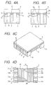
- Fig. 4C shows an application of the common mode filter according to the invention to a circuit having eight channels.
- Fig. 4D is a plan view of another embodiment of the common mode filter according to the invention.
- winding portions 2A and 2B each having two windings constituting two pairs are terminals of the windings wound around the winding portion 2A) and 23a, 23b and 24a, 24b are terminals of the windings wound around the winding portion 2B) are spaced from each other by interval G so that the influence of the windings constituting the pair on each other is small as small as possible.
- the winding terminal can be housed in a state of a round wiring, a common mode filter can be provided which is small in size and can be used for a relatively large current.
- the winding terminal will not be broken since it is not required to be flattened.
- the winding terminal is housed in the gap formed by the concave portion, the height of the upper face of the plate-like core can be suppressed, thus providing a low-profiled common mode filter for a relatively large current.
- the electrode is provided so as to be successive over the upper surface, end surface and lower surface of the flange, the electrode portion on the upper surface of the flange to which the winding terminal is connected is discriminated from the electrode portion on the end surface and lower surface of the flange which is to be used for mounting on the printed board, and the electrode portion on the upper surface of the flange which may be deteriorated when the winding terminal is connected is not used for mounting. For this reason, the adverse effect on the capability of soldering can be prevented. Furthermore, since the electrode is provided so as to be successive over the upper surface, end surface and lower surface of the flange, on the end surface of the flange, the fixing state of the solder on the electrodes can be visually recognized.
- the winding terminals are reinforced and the quantity of the adhesive is assured so that the plate-like core can be firmly secured to the drum-shaped core.
Landscapes
- Engineering & Computer Science (AREA)
- Power Engineering (AREA)
- Microelectronics & Electronic Packaging (AREA)
- Coils Or Transformers For Communication (AREA)
- Filters And Equalizers (AREA)
Applications Claiming Priority (2)
| Application Number | Priority Date | Filing Date | Title |
|---|---|---|---|
| JP26623999 | 1999-09-20 | ||
| JP26623999A JP3710042B2 (ja) | 1999-09-20 | 1999-09-20 | コモンモードフィルタ |
Publications (2)
| Publication Number | Publication Date |
|---|---|
| EP1085533A1 true EP1085533A1 (fr) | 2001-03-21 |
| EP1085533B1 EP1085533B1 (fr) | 2007-11-14 |
Family
ID=17428217
Family Applications (1)
| Application Number | Title | Priority Date | Filing Date |
|---|---|---|---|
| EP00120477A Expired - Lifetime EP1085533B1 (fr) | 1999-09-20 | 2000-09-19 | Filtre de mode commun |
Country Status (6)
| Country | Link |
|---|---|
| US (1) | US6373366B1 (fr) |
| EP (1) | EP1085533B1 (fr) |
| JP (1) | JP3710042B2 (fr) |
| KR (1) | KR100590338B1 (fr) |
| CN (1) | CN1156962C (fr) |
| DE (1) | DE60037085T2 (fr) |
Cited By (4)
| Publication number | Priority date | Publication date | Assignee | Title |
|---|---|---|---|---|
| WO2008065824A1 (fr) | 2006-12-01 | 2008-06-05 | Murata Manufacturing Co., Ltd. | Bobine de blocage en mode commun |
| EP2172950A4 (fr) * | 2007-07-11 | 2013-01-23 | Murata Manufacturing Co | Bobine d'arrêt en mode commun |
| EP2161727A4 (fr) * | 2007-05-14 | 2016-10-05 | Murata Manufacturing Co | Bobine d'arret en mode commun |
| US11250983B2 (en) * | 2017-09-21 | 2022-02-15 | Murata Manufacturing Co., Ltd. | Coil component |
Families Citing this family (66)
| Publication number | Priority date | Publication date | Assignee | Title |
|---|---|---|---|---|
| WO2001000971A1 (fr) * | 1999-06-23 | 2001-01-04 | N.V. Bekaert S.A. | Systeme filtrant d'echappement diesel avec regeneration electrique |
| JP2002008931A (ja) * | 2000-04-18 | 2002-01-11 | Taiyo Yuden Co Ltd | 巻線型コモンモードチョークコイル |
| JP3395764B2 (ja) * | 2000-07-17 | 2003-04-14 | 株式会社村田製作所 | チップ型コモンモードチョークコイル |
| JP3755488B2 (ja) * | 2001-08-09 | 2006-03-15 | 株式会社村田製作所 | 巻線型チップコイルおよびその特性調整方法 |
| JP4312409B2 (ja) * | 2002-02-12 | 2009-08-12 | Tdk株式会社 | コモンモードフィルタ |
| WO2004041080A2 (fr) * | 2002-10-31 | 2004-05-21 | Medtronic, Inc. | Indication de zone corporelle |
| US6778055B1 (en) * | 2003-02-07 | 2004-08-17 | Aoba Technology Co., Ltd. | Core member for winding |
| JP4203950B2 (ja) * | 2003-08-07 | 2009-01-07 | Tdk株式会社 | コモンモードフィルタ及びその製造方法 |
| JP3946207B2 (ja) * | 2004-04-20 | 2007-07-18 | Tdk株式会社 | コイル部品 |
| JP4033852B2 (ja) * | 2004-06-01 | 2008-01-16 | Tdk株式会社 | コモンモードフィルタ |
| US7612641B2 (en) * | 2004-09-21 | 2009-11-03 | Pulse Engineering, Inc. | Simplified surface-mount devices and methods |
| JP4776204B2 (ja) * | 2004-10-12 | 2011-09-21 | Tdk株式会社 | コイル部品の製造方法 |
| US7790574B2 (en) | 2004-12-20 | 2010-09-07 | Georgia Tech Research Corporation | Boron diffusion in silicon devices |
| JP4780111B2 (ja) * | 2005-11-22 | 2011-09-28 | 株式会社村田製作所 | 巻線型コイル |
| JP4184395B2 (ja) * | 2006-06-30 | 2008-11-19 | Tdk株式会社 | コイル部品及びコイル部品の製造方法 |
| JP4184394B2 (ja) * | 2006-06-30 | 2008-11-19 | Tdk株式会社 | コイル部品及びコイル部品の製造方法 |
| CN101501791A (zh) * | 2006-07-14 | 2009-08-05 | 美商·帕斯脉冲工程有限公司 | 自引线表面安装电感器和方法 |
| JP4835946B2 (ja) * | 2007-06-28 | 2011-12-14 | 株式会社村田製作所 | コモンモードチョークコイル |
| DE102007036052A1 (de) * | 2007-08-01 | 2009-02-05 | Epcos Ag | Stromkompensierte Drossel und Schaltungsanordnung mit einer stromkompensierten Drossel |
| JP4789076B2 (ja) * | 2007-12-14 | 2011-10-05 | Tdk株式会社 | コイル部品 |
| JP5119978B2 (ja) * | 2008-02-28 | 2013-01-16 | Tdk株式会社 | 電子部品の実装構造 |
| JP4708469B2 (ja) * | 2008-02-29 | 2011-06-22 | Tdk株式会社 | バルントランス |
| JP4984172B2 (ja) * | 2008-06-26 | 2012-07-25 | Tdk株式会社 | コイル部品 |
| JP5223583B2 (ja) * | 2008-10-10 | 2013-06-26 | Tdk株式会社 | バルントランス |
| JP4807397B2 (ja) * | 2008-10-10 | 2011-11-02 | Tdk株式会社 | バルントランス |
| US20110175698A1 (en) * | 2010-01-20 | 2011-07-21 | Jenq-Gong Duh | Inductor with ferromagnetic metal film |
| JP5747667B2 (ja) * | 2011-06-08 | 2015-07-15 | Tdk株式会社 | コイル部品 |
| US8686822B2 (en) * | 2011-08-22 | 2014-04-01 | Hon Hai Precision Industry Co., Ltd. | Surface mounted pulse transformer |
| JP5844765B2 (ja) | 2013-03-27 | 2016-01-20 | Tdk株式会社 | パルストランス及びこれを備えた回路部品 |
| JP1527694S (fr) | 2013-10-11 | 2015-06-29 | ||
| US20150206649A1 (en) * | 2014-01-23 | 2015-07-23 | Kinnexa, Inc. | Improved structure of smd (surface mount device) type signal transformer |
| USD790468S1 (en) * | 2014-02-26 | 2017-06-27 | Nishimoto Gosei Hanbai Co., Ltd. | Coil bobbin for transformer |
| DE102014103324B4 (de) | 2014-03-12 | 2022-11-24 | Tdk Electronics Ag | Induktives Bauelement und Verfahren zum Herstellen eines induktiven Bauelements |
| JP6435649B2 (ja) * | 2014-06-05 | 2018-12-12 | Tdk株式会社 | コイル部品及びその製造方法 |
| JP6264255B2 (ja) * | 2014-10-17 | 2018-01-24 | 株式会社村田製作所 | コモンモードチョークコイル |
| USD798814S1 (en) * | 2014-12-02 | 2017-10-03 | Tdk Corporation | Coil component |
| US10645811B2 (en) | 2015-07-02 | 2020-05-05 | Pulse Electronics, Inc. | Inductive devices with splits and methods of making and using the same |
| JP6024814B1 (ja) * | 2015-11-02 | 2016-11-16 | Tdk株式会社 | 磁気センサ用インダクタンス素子及びこれを備える電流センサ |
| US11069468B2 (en) * | 2016-08-09 | 2021-07-20 | Panasonic Intellectual Property Management Co., Ltd. | Common mode choke coil and manufacturing method therefor |
| US10192675B2 (en) | 2016-08-16 | 2019-01-29 | Tai-Tech Advanced Electronics Co., Ltd. | Pulse transformer |
| JP6759965B2 (ja) * | 2016-10-19 | 2020-09-23 | Tdk株式会社 | 磁気センサ用インダクタンス素子及びこれを備える電流センサ |
| TWD183205S (zh) * | 2016-11-14 | 2017-05-21 | 群光電能科技股份有限公司 | 繞線架 |
| JP6577970B2 (ja) * | 2017-03-31 | 2019-09-18 | 太陽誘電株式会社 | コモンモードチョークコイル及びその製造方法、回路基板。 |
| JP6875198B2 (ja) * | 2017-05-31 | 2021-05-19 | 株式会社村田製作所 | インダクタ |
| JP6891767B2 (ja) * | 2017-11-18 | 2021-06-18 | 株式会社村田製作所 | コイル部品 |
| US20190156984A1 (en) * | 2017-11-22 | 2019-05-23 | Tai-Tech Advanced Electronics Co., Ltd. | Transformer structure |
| JP6702296B2 (ja) * | 2017-12-08 | 2020-06-03 | 株式会社村田製作所 | 電子部品 |
| US10770219B2 (en) * | 2017-12-20 | 2020-09-08 | Tdk Corporation | Coil component |
| JP6784266B2 (ja) * | 2018-01-30 | 2020-11-11 | 株式会社村田製作所 | コイル部品及びコイル部品の製造方法 |
| CN110246681B (zh) * | 2018-03-07 | 2022-07-08 | 株式会社村田制作所 | 线圈部件的制造方法和线圈部件的制造装置 |
| JP6730397B2 (ja) * | 2018-09-28 | 2020-07-29 | 太陽誘電株式会社 | コイル部品及び電子機器 |
| JP6943235B2 (ja) * | 2018-12-24 | 2021-09-29 | 株式会社村田製作所 | コイル部品 |
| JP7557931B2 (ja) * | 2019-08-30 | 2024-09-30 | Tdk株式会社 | コイル部品 |
| USD911284S1 (en) * | 2019-12-18 | 2021-02-23 | Changzhou Jutai Electronic Co., Ltd. | Transformer skeleton |
| USD911283S1 (en) * | 2019-12-18 | 2021-02-23 | Changzhou Jutai Electronic Co., Ltd. | Transformer skeleton |
| JP7456196B2 (ja) * | 2020-03-03 | 2024-03-27 | Tdk株式会社 | コイル部品 |
| JP7456195B2 (ja) * | 2020-03-03 | 2024-03-27 | Tdk株式会社 | コイル部品 |
| USD1047910S1 (en) * | 2020-09-07 | 2024-10-22 | Tdk Corporation | Coil component |
| JP7609591B2 (ja) * | 2020-09-25 | 2025-01-07 | 株式会社村田製作所 | コイル部品 |
| JP2022161282A (ja) * | 2021-04-08 | 2022-10-21 | 株式会社村田製作所 | コイル部品 |
| JP7420107B2 (ja) * | 2021-04-08 | 2024-01-23 | 株式会社村田製作所 | コイル部品 |
| JP1715037S (ja) * | 2021-06-29 | 2022-05-17 | コイル部品 | |
| JP7501462B2 (ja) * | 2021-07-13 | 2024-06-18 | 株式会社村田製作所 | コイル部品 |
| JP2023042907A (ja) * | 2021-09-15 | 2023-03-28 | 株式会社村田製作所 | インダクタ部品 |
| JP7807216B2 (ja) * | 2021-11-22 | 2026-01-27 | Tdk株式会社 | コイル装置 |
| JP7513005B2 (ja) * | 2021-12-01 | 2024-07-09 | 株式会社村田製作所 | コイル部品 |
Citations (6)
| Publication number | Priority date | Publication date | Assignee | Title |
|---|---|---|---|---|
| JPH08186028A (ja) * | 1994-12-28 | 1996-07-16 | Tokin Corp | ギャップ付き巻線チップインダクタ |
| JPH08213248A (ja) * | 1995-02-02 | 1996-08-20 | Koa Corp | チップインダクタ |
| JPH08264343A (ja) * | 1995-03-22 | 1996-10-11 | Matsushita Electric Ind Co Ltd | チップコモンモードチョークおよびその製造方法 |
| JPH08306537A (ja) * | 1995-04-28 | 1996-11-22 | Taiyo Yuden Co Ltd | チップ状インダクタ |
| JPH10172822A (ja) * | 1996-12-06 | 1998-06-26 | Taiyo Yuden Co Ltd | 巻線型電子部品及びその製造方法 |
| US5805431A (en) * | 1996-01-17 | 1998-09-08 | Synergy Microwave Corporation | Surface Mountable transformer |
Family Cites Families (14)
| Publication number | Priority date | Publication date | Assignee | Title |
|---|---|---|---|---|
| US3585553A (en) * | 1970-04-16 | 1971-06-15 | Us Army | Microminiature leadless inductance element |
| JP3219586B2 (ja) | 1994-03-01 | 2001-10-15 | ティーディーケイ株式会社 | ノーマルモード・コモンモード兼用チョークコイル |
| JPH07297049A (ja) | 1994-04-28 | 1995-11-10 | Taiyo Yuden Co Ltd | 面実装型コイル |
| JPH0831644A (ja) | 1994-07-18 | 1996-02-02 | Taiyo Yuden Co Ltd | 面実装型電極直付けインダクタ |
| JPH08186034A (ja) | 1995-01-06 | 1996-07-16 | Murata Mfg Co Ltd | 巻線型コイル部品 |
| JPH08186035A (ja) | 1995-01-06 | 1996-07-16 | Murata Mfg Co Ltd | コイル部品 |
| JPH08236356A (ja) | 1995-02-28 | 1996-09-13 | Mitsumi Electric Co Ltd | 複合素子 |
| JPH08306559A (ja) | 1995-05-01 | 1996-11-22 | Taiyo Yuden Co Ltd | コイル部品 |
| JPH09190942A (ja) | 1996-01-11 | 1997-07-22 | Murata Mfg Co Ltd | チップ型コイルの製造方法 |
| JPH10163029A (ja) | 1996-11-26 | 1998-06-19 | Tokin Corp | コモンモードチョークコイル |
| US6144280A (en) * | 1996-11-29 | 2000-11-07 | Taiyo Yuden Co., Ltd. | Wire wound electronic component and method of manufacturing the same |
| JP3091713B2 (ja) | 1997-05-23 | 2000-09-25 | ティーディーケイ株式会社 | 巻線型チップバルントランス |
| JP3168972B2 (ja) | 1998-01-14 | 2001-05-21 | 株式会社村田製作所 | チップ型コモンモードチョークコイル |
| JP3195585B2 (ja) | 1998-10-27 | 2001-08-06 | ティーディーケイ株式会社 | 表面実装自己誘導型インダクタンス部品 |
-
1999
- 1999-09-20 JP JP26623999A patent/JP3710042B2/ja not_active Expired - Lifetime
-
2000
- 2000-09-18 KR KR1020000054540A patent/KR100590338B1/ko not_active Expired - Lifetime
- 2000-09-19 EP EP00120477A patent/EP1085533B1/fr not_active Expired - Lifetime
- 2000-09-19 US US09/664,831 patent/US6373366B1/en not_active Expired - Lifetime
- 2000-09-19 DE DE60037085T patent/DE60037085T2/de not_active Expired - Lifetime
- 2000-09-20 CN CNB00128777XA patent/CN1156962C/zh not_active Expired - Lifetime
Patent Citations (6)
| Publication number | Priority date | Publication date | Assignee | Title |
|---|---|---|---|---|
| JPH08186028A (ja) * | 1994-12-28 | 1996-07-16 | Tokin Corp | ギャップ付き巻線チップインダクタ |
| JPH08213248A (ja) * | 1995-02-02 | 1996-08-20 | Koa Corp | チップインダクタ |
| JPH08264343A (ja) * | 1995-03-22 | 1996-10-11 | Matsushita Electric Ind Co Ltd | チップコモンモードチョークおよびその製造方法 |
| JPH08306537A (ja) * | 1995-04-28 | 1996-11-22 | Taiyo Yuden Co Ltd | チップ状インダクタ |
| US5805431A (en) * | 1996-01-17 | 1998-09-08 | Synergy Microwave Corporation | Surface Mountable transformer |
| JPH10172822A (ja) * | 1996-12-06 | 1998-06-26 | Taiyo Yuden Co Ltd | 巻線型電子部品及びその製造方法 |
Non-Patent Citations (5)
| Title |
|---|
| PATENT ABSTRACTS OF JAPAN vol. 1996, no. 11 29 November 1996 (1996-11-29) * |
| PATENT ABSTRACTS OF JAPAN vol. 1996, no. 12 26 December 1996 (1996-12-26) * |
| PATENT ABSTRACTS OF JAPAN vol. 1997, no. 02 28 February 1997 (1997-02-28) * |
| PATENT ABSTRACTS OF JAPAN vol. 1997, no. 03 31 March 1997 (1997-03-31) * |
| PATENT ABSTRACTS OF JAPAN vol. 1998, no. 11 30 September 1998 (1998-09-30) * |
Cited By (5)
| Publication number | Priority date | Publication date | Assignee | Title |
|---|---|---|---|---|
| WO2008065824A1 (fr) | 2006-12-01 | 2008-06-05 | Murata Manufacturing Co., Ltd. | Bobine de blocage en mode commun |
| EP2087494A4 (fr) * | 2006-12-01 | 2015-09-09 | Murata Manufacturing Co | Bobine de blocage en mode commun |
| EP2161727A4 (fr) * | 2007-05-14 | 2016-10-05 | Murata Manufacturing Co | Bobine d'arret en mode commun |
| EP2172950A4 (fr) * | 2007-07-11 | 2013-01-23 | Murata Manufacturing Co | Bobine d'arrêt en mode commun |
| US11250983B2 (en) * | 2017-09-21 | 2022-02-15 | Murata Manufacturing Co., Ltd. | Coil component |
Also Published As
| Publication number | Publication date |
|---|---|
| CN1289179A (zh) | 2001-03-28 |
| DE60037085T2 (de) | 2008-02-28 |
| JP3710042B2 (ja) | 2005-10-26 |
| KR20010067186A (ko) | 2001-07-12 |
| JP2001093756A (ja) | 2001-04-06 |
| US6373366B1 (en) | 2002-04-16 |
| EP1085533B1 (fr) | 2007-11-14 |
| DE60037085D1 (de) | 2007-12-27 |
| KR100590338B1 (ko) | 2006-06-15 |
| CN1156962C (zh) | 2004-07-07 |
Similar Documents
| Publication | Publication Date | Title |
|---|---|---|
| EP1085533B1 (fr) | Filtre de mode commun | |
| US6373714B1 (en) | Surface mounting part | |
| US20060022788A1 (en) | Surface mount coil component | |
| JP2000269050A (ja) | コモンモードチョークコイル | |
| JPH06131919A (ja) | フレキシブル配線ケーブル | |
| JP2003077730A (ja) | コモンモードチョークコイル | |
| JPH11238634A (ja) | 面実装型コイル部品 | |
| US12278034B2 (en) | Coil device | |
| JP2020057788A (ja) | プリント回路板及びそれを含むモータ | |
| JP2003068531A (ja) | インダクタ及びインダクタの製造方法 | |
| US20110122589A1 (en) | Magnetic element having improved transformers and commom mode chokes | |
| JPH10303039A (ja) | 変成器 | |
| US5203077A (en) | Method for mounting large discrete electronic components | |
| JPH11176659A (ja) | 低背チップ型コイル素子 | |
| JP2967222B2 (ja) | モジュラージャック及びその製造方法 | |
| JP3461126B2 (ja) | スイッチング電源用回路ブロック | |
| JP2001284870A (ja) | 高周波シールド構造 | |
| JP2001223604A (ja) | 無線通信モジュール | |
| JP2004281777A (ja) | チョークコイル | |
| JP2000269049A (ja) | コモンモードチョークコイル | |
| JP2524604B2 (ja) | 平面実装型巻線部品 | |
| TW464886B (en) | Common mode filter | |
| JPH08236356A (ja) | 複合素子 | |
| JPH11102816A (ja) | 磁気結合を有するチップ部品 | |
| JP2601406Y2 (ja) | コイル |
Legal Events
| Date | Code | Title | Description |
|---|---|---|---|
| PUAI | Public reference made under article 153(3) epc to a published international application that has entered the european phase |
Free format text: ORIGINAL CODE: 0009012 |
|
| AK | Designated contracting states |
Kind code of ref document: A1 Designated state(s): AT BE CH CY DE DK ES FI FR GB GR IE IT LI LU MC NL PT SE |
|
| AX | Request for extension of the european patent |
Free format text: AL;LT;LV;MK;RO;SI |
|
| 17P | Request for examination filed |
Effective date: 20010430 |
|
| AKX | Designation fees paid |
Free format text: DE FR GB NL |
|
| GRAP | Despatch of communication of intention to grant a patent |
Free format text: ORIGINAL CODE: EPIDOSNIGR1 |
|
| GRAS | Grant fee paid |
Free format text: ORIGINAL CODE: EPIDOSNIGR3 |
|
| GRAA | (expected) grant |
Free format text: ORIGINAL CODE: 0009210 |
|
| AK | Designated contracting states |
Kind code of ref document: B1 Designated state(s): DE FR GB NL |
|
| REG | Reference to a national code |
Ref country code: GB Ref legal event code: FG4D |
|
| REF | Corresponds to: |
Ref document number: 60037085 Country of ref document: DE Date of ref document: 20071227 Kind code of ref document: P |
|
| ET | Fr: translation filed | ||
| PLBE | No opposition filed within time limit |
Free format text: ORIGINAL CODE: 0009261 |
|
| STAA | Information on the status of an ep patent application or granted ep patent |
Free format text: STATUS: NO OPPOSITION FILED WITHIN TIME LIMIT |
|
| 26N | No opposition filed |
Effective date: 20080815 |
|
| PGFP | Annual fee paid to national office [announced via postgrant information from national office to epo] |
Ref country code: GB Payment date: 20120919 Year of fee payment: 13 |
|
| PGFP | Annual fee paid to national office [announced via postgrant information from national office to epo] |
Ref country code: FR Payment date: 20120926 Year of fee payment: 13 |
|
| PGFP | Annual fee paid to national office [announced via postgrant information from national office to epo] |
Ref country code: NL Payment date: 20120919 Year of fee payment: 13 |
|
| REG | Reference to a national code |
Ref country code: NL Ref legal event code: V1 Effective date: 20140401 |
|
| GBPC | Gb: european patent ceased through non-payment of renewal fee |
Effective date: 20130919 |
|
| REG | Reference to a national code |
Ref country code: FR Ref legal event code: ST Effective date: 20140530 |
|
| PG25 | Lapsed in a contracting state [announced via postgrant information from national office to epo] |
Ref country code: GB Free format text: LAPSE BECAUSE OF NON-PAYMENT OF DUE FEES Effective date: 20130919 |
|
| PG25 | Lapsed in a contracting state [announced via postgrant information from national office to epo] |
Ref country code: NL Free format text: LAPSE BECAUSE OF NON-PAYMENT OF DUE FEES Effective date: 20140401 Ref country code: FR Free format text: LAPSE BECAUSE OF NON-PAYMENT OF DUE FEES Effective date: 20130930 |
|
| PGFP | Annual fee paid to national office [announced via postgrant information from national office to epo] |
Ref country code: DE Payment date: 20190903 Year of fee payment: 20 |
|
| REG | Reference to a national code |
Ref country code: DE Ref legal event code: R071 Ref document number: 60037085 Country of ref document: DE |