EP1086802B1 - Presse avec entraînement à vilebrequin pour le poinçon supérieur et son procédé de fonctionnement - Google Patents
Presse avec entraînement à vilebrequin pour le poinçon supérieur et son procédé de fonctionnement Download PDFInfo
- Publication number
- EP1086802B1 EP1086802B1 EP00250306A EP00250306A EP1086802B1 EP 1086802 B1 EP1086802 B1 EP 1086802B1 EP 00250306 A EP00250306 A EP 00250306A EP 00250306 A EP00250306 A EP 00250306A EP 1086802 B1 EP1086802 B1 EP 1086802B1
- Authority
- EP
- European Patent Office
- Prior art keywords
- press
- press according
- hydraulic
- upper punch
- crankshaft
- Prior art date
- Legal status (The legal status is an assumption and is not a legal conclusion. Google has not performed a legal analysis and makes no representation as to the accuracy of the status listed.)
- Expired - Lifetime
Links
- 238000011017 operating method Methods 0.000 title 1
- 230000007246 mechanism Effects 0.000 claims abstract description 8
- 230000002441 reversible effect Effects 0.000 claims abstract 2
- 238000003825 pressing Methods 0.000 claims description 41
- 239000000843 powder Substances 0.000 claims description 17
- 239000002184 metal Substances 0.000 claims description 3
- 238000005259 measurement Methods 0.000 claims 1
- 239000000126 substance Substances 0.000 claims 1
- 238000000034 method Methods 0.000 abstract description 4
- 230000008569 process Effects 0.000 abstract description 4
- 230000033001 locomotion Effects 0.000 description 21
- 238000004519 manufacturing process Methods 0.000 description 7
- 230000008901 benefit Effects 0.000 description 6
- 230000005540 biological transmission Effects 0.000 description 6
- 238000000418 atomic force spectrum Methods 0.000 description 4
- 230000006835 compression Effects 0.000 description 4
- 238000007906 compression Methods 0.000 description 4
- 230000008859 change Effects 0.000 description 3
- 238000005056 compaction Methods 0.000 description 3
- 238000005265 energy consumption Methods 0.000 description 3
- 238000005516 engineering process Methods 0.000 description 3
- 239000012530 fluid Substances 0.000 description 3
- 230000000750 progressive effect Effects 0.000 description 3
- 230000001419 dependent effect Effects 0.000 description 2
- 241001133184 Colletotrichum agaves Species 0.000 description 1
- 230000009471 action Effects 0.000 description 1
- 239000000919 ceramic Substances 0.000 description 1
- 238000010276 construction Methods 0.000 description 1
- 238000013461 design Methods 0.000 description 1
- 238000011161 development Methods 0.000 description 1
- 230000018109 developmental process Effects 0.000 description 1
- 238000006073 displacement reaction Methods 0.000 description 1
- 230000002349 favourable effect Effects 0.000 description 1
- 238000012423 maintenance Methods 0.000 description 1
- 238000000465 moulding Methods 0.000 description 1
- 238000004904 shortening Methods 0.000 description 1
- 238000013519 translation Methods 0.000 description 1
Images

Classifications
-
- B—PERFORMING OPERATIONS; TRANSPORTING
- B30—PRESSES
- B30B—PRESSES IN GENERAL
- B30B1/00—Presses, using a press ram, characterised by the features of the drive therefor, pressure being transmitted directly, or through simple thrust or tension members only, to the press ram or platen
- B30B1/26—Presses, using a press ram, characterised by the features of the drive therefor, pressure being transmitted directly, or through simple thrust or tension members only, to the press ram or platen by cams, eccentrics, or cranks
- B30B1/266—Drive systems for the cam, eccentric or crank axis
-
- B—PERFORMING OPERATIONS; TRANSPORTING
- B30—PRESSES
- B30B—PRESSES IN GENERAL
- B30B1/00—Presses, using a press ram, characterised by the features of the drive therefor, pressure being transmitted directly, or through simple thrust or tension members only, to the press ram or platen
- B30B1/26—Presses, using a press ram, characterised by the features of the drive therefor, pressure being transmitted directly, or through simple thrust or tension members only, to the press ram or platen by cams, eccentrics, or cranks
- B30B1/28—Presses, using a press ram, characterised by the features of the drive therefor, pressure being transmitted directly, or through simple thrust or tension members only, to the press ram or platen by cams, eccentrics, or cranks the cam, crank, or eccentric being disposed below the lower platen or table and operating to pull down the upper platen or slide
-
- B—PERFORMING OPERATIONS; TRANSPORTING
- B30—PRESSES
- B30B—PRESSES IN GENERAL
- B30B11/00—Presses specially adapted for forming shaped articles from material in particulate or plastic state, e.g. briquetting presses, tabletting presses
- B30B11/02—Presses specially adapted for forming shaped articles from material in particulate or plastic state, e.g. briquetting presses, tabletting presses using a ram exerting pressure on the material in a moulding space
Definitions
- the invention relates to a press for pressing pulverulent masses, in particular of metal powder, with an eccentric crank drive having at least one connecting rod and a crankshaft for driving a punch unit according to the preamble of patent claim 1.
- mechanical powder presses have been used for many years for the production of powder compacts. These usually designed as eccentric presses or toggle presses mechanical presses are characterized by a high operating speed at sinusoidal course of the punch movement at a highly progressive force profile during the work cycle.
- the pressing tools are moved by hydraulic piston / cylinder systems.
- the individual pressing tools can be optimally controlled in terms of pressing force and pressing path so that compacts arise that are characterized despite their complicated shape by a largely constant density within the body volume.
- hydraulic presses In comparison to mechanical presses, however, hydraulic presses generally have a lower operating speed, ie longer cycle times, and have a significantly higher energy consumption.
- a press for pressing powdery masses which is designed as a mechanical eccentric press with an electric drive motor for the movement of the upper punch of the press.
- the crankshaft of the eccentric drive for the upper punch is rotatably connected to a gear which is moved by a worm gear, the in turn is rotated by an electric motor.
- the direction of rotation of the electric motor and the crankshaft does not change during operation.
- a hydraulic piston / cylinder system is provided for the movement of the die .
- the peculiarity of this known press is that it has a coding switch which scans the working position of the upper punch and supplies a corresponding signal to the electronic control of this press.
- a frequency converter acts on the electric drive motor and receives control signals from the electronic control, so that the drive movement is controllable.
- the upper punch is mounted in a pressure measuring cylinder and displaceable in the pressing direction, said hydraulic displacement of the upper punch is guided by the electronic press control.
- Object of the present invention is to develop a press of the generic type such that the known of the mechanical presses and advantageous for compacting the compressed powder sinusoidal motion and progressive force curve is connected to the advantages caused by a comparatively simple hydraulic drive technology advantages in terms of high flexibility the press and a close to the ideal course of the press process with high reproducibility of speed and position of the pressing tools.
- the energy consumption of this press should be small in relation to the drive forces generated by it.
- the pressing parameters should be easily adjustable to optimize the movement and the power requirements.
- the press according to the invention has an eccentric crank drive for driving its upper punch unit, which includes at least one connecting rod (usually arranged in pairs), which is connected at one end to the upper punch unit and at its other end eccentrically to a crankshaft.
- the connection with the crankshaft can be realized for example via an eccentric disc.
- a gear is rotatably connected.
- This gear is rotatable by at least one, preferably two drive screws, which are expedient diametrically opposite to the crankshaft and in turn are driven by at least one motor, preferably each of a separate motor.
- the movements of this press are managed by an electronic control.
- An essential feature of the invention is that this electronic control is set up for a reversing operation of the crankshaft.
- the crankshaft is rotated over an angular range of less than 180 °.
- the upper punch unit moves up and down as a result of the power transmission through the connecting rod, ie between pressing position and filling / ejection position back and forth.
- the crankshaft thus does not execute any complete revolutions in the case of the press according to the invention.
- the controller is set up so that the preferably two hydraulic motors of the press with respect to their involvement in the circuit of the hydraulic means are selectively connected in parallel and in succession.
- parallel connection half of the flow rate passes through the motor in the case of two hydraulic motors, while in the case of a series connection by the two motors, in each case the full mass flow passes through. That means at unchanged hydraulic unit, the setting of a normal or a twice as high working speed. The latter is particularly advantageous in the compression of smaller parts with low overall height.
- the press includes a die, which is controlled by hydraulic cylinders in web control movable, as is generally known in hydraulic presses.
- the press may comprise a hydraulically actuated tool adapter.
- a central electric motor which drives a hydraulic pump for the upper punch unit and a further hydraulic pump for the hydraulic cylinder of the die and / or the hydraulically actuated tool adapter.
- an electronic measuring system for detecting the current position of the upper bear of the press, which receives the upper punch unit, or an electronic rotary encoder for detecting the current angular position of the crankshaft may be provided.
- the particular advantage of the press according to the invention whose movements of their pressing tool parts are guided by the electronic control, is that preferably be taken directly on the drive of the eccentric crank mechanism via the hydraulically with simple means in terms of volume flow and pressure to be influenced flow of hydraulic fluid can. Both the speed and the torque on the eccentric crank mechanism can therefore be influenced hydraulically very easily and accurately.
- the required pressing force is naturally greatest in the area of bottom dead center of the upper punch unit. Especially in this position of the press but the transmission ratio between driving force and pressing force is also greatest.
- the drive power required for the press drive can be chosen to be much lower compared to a hydraulic press equipped with the same maximum press force. As a result, the total energy consumption during a Presszyklusses is much lower.
- the press according to the invention allows cycle times which are even lower than those of a conventional electric eccentric continuous mechanical eccentric crank press. This is possible when the press control is adjusted so that the stroke ends each well before reaching the top dead center of the eccentric crank and then reversed. In a conventional mechanical press this way must always be fully traversed.
- the cycle time of a conventional mechanical press is significantly influenced by the necessary processes during the exposure of the compact. This includes in particular the necessary maintenance of a loading force during the removal of the die, which is applied by a hydraulic cylinder / piston system accommodated in the upper punch drive unit. In continuous operation, this cylinder / piston system must perform an extension movement to maintain the Auflastekraft corresponding to the return movement of the upper punch drive unit and return as quickly as possible after pulling off the die back to the starting position. This requires either a particularly powerful (expensive) hydraulics or an adjustment of the basic speed (speed) of the press to the time required for the movement of the cylinder / piston system.
- the speed of the top punch drive unit in the area of the bottom dead center can be greatly reduced or even kept temporarily at zero until the compact is exposed.
- the hydraulic effort for the cylinder movements for the loading force can be kept very small.
- the top punch drive unit can be returned to its original position at the maximum possible speed.
- a likewise advantageous operation of the press according to the invention results when the stroke is adjusted in the region of the bottom dead center of the upper punch unit so that the bottom dead center is run over by a small piece.
- the press is thus operated in the range of a crank angle which is slightly above 180 ° (absolute angle). After reaching the end point, the dead center is inevitably run over again at 180 ° because of the fundamentally reversing operation of the press. This means that in a very simple way a double pressing with maximum pressing force at bottom dead center at each Working cycle takes place. This has a special advantage for certain pressed parts.
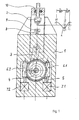
- FIG. 1 is a schematic representation of a press according to the invention in the sectional view, wherein only the drive of a punch unit 2 (ie, the upper bear of the press in which the upper punch unit is mounted) is reproduced.
- This upper punch unit 2 in which one or more upper punches are held depending on the shape of the compact to be produced, is slidably mounted in a machine frame 1 of the press.
- the compact is produced in the mold cavity enclosed by a die 9 and a stamping unit 8 which is firmly supported in the machine frame 1 of the press, for example, into which the punch or dies are inserted during pressing.
- a mechanical adjusting device 10 is provided, via which the starting and end position of the upper punch unit 2 are adjustable.
- the upper punch unit 2 is moved by means of a rotatably mounted in the machine frame 1 crankshaft 4.
- a trained as a worm gear 5 is rotatably connected to the crankshaft 4.
- the connecting rod 3 is connected to the crankshaft 4 via an eccentric disc, which may be integral with the gear 5.
- Left and right of the gear 5 are two with respect to the central axis of the crankshaft diametrically opposed screws of two worm gears 6.1, 6.2 arranged. The two screws are each driven by a hydraulic motor 7.1, 7.2.
- an unillustrated electronic rotary encoder is housed, with the help of which indirectly the current position of the upper punch unit 2 can be detected.
- a hydraulic pressure system is provided, which is also not shown in detail and also ensures the supply of other hydraulically driven Preßtechnikmaschinemaschine (eg die, lower punch unit or tool adapter). All movements of the press parts are guided by an electronic control, not shown in Fig. 1, which controls the valves and pumps of the hydraulic system on the basis of the measured values of the rotary encoder or the direct measuring systems used.
- FIG. 1 provides the eccentric crank drive in the lower part of the machine frame 1, it should be much more advantageous in the practical embodiment of a press according to the invention to arrange the eccentric crank mechanism above the upper punch unit 2, ie in the top of the press. This does not change the basic functionality.
- the two screws of the worm drives 6.1 and 6.2 are acted upon by the hydraulic motors 7.1, 7.2 with the hydraulic pump pumped by a hydraulic pump and cause according to the gear ratio of the worm drives 6.1, 6.2, a torque on the gear 5 and a corresponding rotational movement of the crankshaft 4.
- the electronic control designed so that, by switching the direction of rotation of the hydraulic motors 7.1, 7.2 a reversing rotary motion on the crankshaft 4 over an angular range of z. B. 120 °. With an appropriate choice of the number of revolutions of the hydraulic motors 7.1, 7.2, the crank drive moves into the area of bottom dead center.
- the control of the press can be set up so that, as required, a press end position beyond the bottom dead center of the connecting rod 3 is achieved. In this case, the absolute dead center of the pressing position is then run over once in the actual working cycle and then again at the beginning of the "empty cycle", so that a double pressing is effected.
- the crankshaft By shortening the rotation of the crankshaft to a range of well below 180 °, the need to completely pass through the relatively time-consuming valley and / or the peak of the sinusoidal movement curve is avoided. This can easily save about 30-50% of the cycle time.
- the press according to the invention thus advantageously combines a slow working travel with a large pressing force and a fast return journey with a lower force.
- the drive power of the press can be used in this way over the duration of the pressing cycle much more uniform than is the case with a conventional hydraulic press.
- the parallel or the series connection can be maintained unchanged during the entire pressing cycle, the latter is particularly recommended for achieving a high production capacity for pressing parts with comparatively low height, are sufficient for the lower compressive forces.
- the press according to the invention can also be operated in continuous operation, ie without reversing the drive motors, like a conventional mechanical press. This still gives the advantage of easy adaptability of the working speed.
- an electronic control is provided for the press, which allows a web control with freely programmable controlled positions and speeds.
- the sinusoidal profile of the path traveled by the upper punch unit 2 as a function of time is shown.
- the crankshaft rotation is 180 °, with the upper punch unit 2 moving from top dead center OT to bottom dead center UT.
- the time required for this (compression stroke) is denoted by t. Since the subsequent return movement from bottom dead center UT to top dead center OT is not performed in hydraulic parallel, but in series connection of the hydraulic motors 7.1, 7.2, is indeed true an equal rotation of the crankshaft 4 ago, but the time required has become smaller due to the constant flow rate of the hydraulic pump and is only t r .
- the second part of the sinusoid is therefore correspondingly compressed in the direction of the time axis.
- dash-dotted lines and the sign +/- is indicated in the graph that the end position of the upper punch unit in the dead center in the positive or negative direction can be varied.
- the part of the power stroke in which the powder is compressed in the mold is denoted by A.
- FIG. 2 in the sense of an embodiment, as a function of the crank angle ⁇ of the eccentric crank drive, the curves of some characteristics of a press according to the invention are shown. Only the section in the range of the crank angle ⁇ from 130 ° to about 180 ° (bottom dead center) is reproduced.
- the example selected relates to a press in which the crank angle range of 130 ° to 180 ° corresponds to a travel distance of the upper punch unit by 40 mm.
- the curve s of the travel path in FIG. 2 thus indicates the distance of the upper punch unit from the bottom dead center. This travel corresponds approximately to the actual pressing process in the press, ie the phase of powder compaction.
- the curve denoted by F represents the course of the actual pressing force in a representative compact having the maximum height that can be processed by the press. With increasing powder compaction, this pressing force F rises sharply from about a crank angle ⁇ of 140 ° to a value of 2340 kN at the bottom dead center.
- the torque M d on the crankshaft belonging to the respective pressing force has a size of 7125 Nm under the given dimensional ratios of the press at a crank angle of 140 °.
- the torque then increases steeply and reaches its maximum at about 160 ° C with a value of 45500 Nm.
- the pressing force in the torque maximum is 1225 kN. After reaching the maximum, the torque drops sharply with increasing crank angle ⁇ and is zero at bottom dead center, while the pressing force reaches its maximum value.
- the torque at the crankshaft is directly proportional to the torque of the hydraulic motors and thus to the hydraulic pressure.
- the tangential force on the toothed wheel 5 in the torque maximum (45,500 Nm) is only 364 KN, while the actual pressing force F acting on the compact is 1225 kN.
- the maximum possible force transmission V is also shown in Figure 2 as a function of the crank angle ⁇ . In particular in the range of the last angular degrees before reaching the bottom dead center results in a strong progressive increase for the power transmission V.
- drive for the upper punch unit is used in powder presses whose other levels of motion (die, tool adapter) are also hydraulically driven and have a common main drive motor for hydraulics.
- This is particularly useful because där power requirements for the upper punch unit and the die usually not simultaneously but successively pending and the greater momentum of a central drive to reduce the peak power at the Oberstkovmaschine in the range of about 160 ° crank angle and later at bottom dead center (Crank angle 180 °) when tearing off the die is conducive.
- the press according to the invention provides a sinusoidal motion and force curve, allows high accuracy in the press bodies to be produced, has high efficiency, is extremely flexible in terms of manufacturable parts, significantly increases production performance and brings a significant advance in manufacturing technology.
Landscapes
- Engineering & Computer Science (AREA)
- Mechanical Engineering (AREA)
- Press Drives And Press Lines (AREA)
- Powder Metallurgy (AREA)
- Presses And Accessory Devices Thereof (AREA)
Claims (14)
- Presse pour comprimer des matières pulvérulentes, en particulier de la poudre de métal, comportant une commande à manivelle à excentrique présentant au moins une bielle (3) et un vilebrequin (4) ainsi qu'une roue dentée (5) reliée à celui-ci de manière solidaire en rotation pour l'actionnement d'une unité de poinçon supérieur (2), la roue dentée (5) pouvant être entraînée par l'intermédiaire d'au moins un engrenage à vis sans fin (6.1, 6.2) par au moins un moteur (7.1, 7.2), et comportant une commande électronique,
caractérisée en ce que la commande électronique est réglée sur un fonctionnement réversible du vilebrequin (4). - Presse selon la revendication 1,
caractérisée en ce que la commande est réglée de telle sorte que le vilebrequin (4) tourne sur une zone angulaire inférieure à 180° pendant la course de travail et de retour. - Presse selon la revendication 1 ou 2,
caractérisée en ce qu'il est prévu deux engrenages à vis sans fin (6.1, 6.2). - Presse selon la revendication 3,
caractérisée en ce que les engrenages à vis sans fin (6.1, 6.2) peuvent être entraînés par des moteurs séparés (7.1, 7.2). - Presse selon l'une des revendications 1 à 4,
caractérisée en ce qu'au moins un moteur (7.1, 7.2) est hydraulique. - Presse selon l'une des revendications 3 à 5,
caractérisée en ce que les deux engrenages à vis sans fin (6.1, 6.2) sont diamétralement opposés de part et d'autre de l'axe de rotation de la roue dentée (5). - Presse selon l'une des revendications 1 à 6,
caractérisée en ce que la commande électronique est réglée de telle sorte que le point mort bas de la commande à manivelle à excentrique est dépassé sur un court trajet afin d'atteindre la position de fin de course de compression (extrémité de la course de travail). - Presse selon l'une des revendications 5 à 7,
caractérisée en ce que la commande électronique est réglée de telle sorte que les deux moteurs hydrauliques (7.1, 7.2) peuvent être mis en marche au choix en même temps ou l'un après l'autre en ce qui concerne leur alimentation hydraulique. - Presse selon l'une des revendications 1 à 8,
caractérisée en ce que la presse comporte une matrice (9) pouvant être déplacée de façon contrôlée par des cylindres hydrauliques. - Presse selon l'une des revendications 1 à 9,
caractérisée en ce que la presse comporte un adaptateur d'outil à actionnement hydraulique. - Presse selon l'une des revendications 9 à 10,
caractérisée en ce qu'il est prévu un moteur électrique central pour actionner l'ensemble des pompes hydrauliques pour l'alimentation en pression des moteurs hydrauliques (7.1, 7.2) pour l'actionnement de l'unité de poinçon supérieur (2) ainsi que pour les cylindres hydrauliques de la matrice (9) et/ou l'adaptateur d'outil à actionnement hydraulique. - Presse selon l'une des revendications 1 à 11,
caractérisée en ce qu'il est prévu un système électronique de mesure de déplacement destiné à détecter la position actuelle de l'unité de poinçon supérieur (2). - Presse selon l'une des revendications 1 à 11,
caractérisée en ce qu'il est prévu un indicateur électronique d'angle de rotation destiné à détecter la position actuelle du vilebrequin (4). - Presse selon l'une des revendications 1 à 13,
caractérisée en ce que la course de l'unité de poinçon supérieur (2) peut être inversée juste avant d'atteindre le point mort haut et/ou bas de la commande à manivelle à excentrique.
Applications Claiming Priority (2)
| Application Number | Priority Date | Filing Date | Title |
|---|---|---|---|
| DE19947689A DE19947689C2 (de) | 1999-09-24 | 1999-09-24 | Presse mit Exzenterkurbeltrieb für Oberstempeleinheit und Betriebsverfahren |
| DE19947689 | 1999-09-24 |
Publications (3)
| Publication Number | Publication Date |
|---|---|
| EP1086802A2 EP1086802A2 (fr) | 2001-03-28 |
| EP1086802A3 EP1086802A3 (fr) | 2002-01-16 |
| EP1086802B1 true EP1086802B1 (fr) | 2006-11-02 |
Family
ID=7924391
Family Applications (1)
| Application Number | Title | Priority Date | Filing Date |
|---|---|---|---|
| EP00250306A Expired - Lifetime EP1086802B1 (fr) | 1999-09-24 | 2000-09-15 | Presse avec entraînement à vilebrequin pour le poinçon supérieur et son procédé de fonctionnement |
Country Status (9)
| Country | Link |
|---|---|
| US (1) | US6564704B1 (fr) |
| EP (1) | EP1086802B1 (fr) |
| JP (1) | JP3723727B2 (fr) |
| CN (1) | CN1187184C (fr) |
| AT (1) | ATE344132T1 (fr) |
| CA (1) | CA2320498C (fr) |
| DE (2) | DE19947689C2 (fr) |
| ES (1) | ES2270788T3 (fr) |
| RU (1) | RU2244627C2 (fr) |
Families Citing this family (12)
| Publication number | Priority date | Publication date | Assignee | Title |
|---|---|---|---|---|
| DE10138664A1 (de) * | 2001-08-02 | 2003-02-20 | Komage Gellner Maschf | Presse und Verfahren zum Betreiben der Presse |
| DE10138665A1 (de) * | 2001-08-02 | 2003-02-20 | Komage Gellner Maschf | Exzenterpresse und Verfahren zum Betreiben der Exzenterpresse |
| US6506118B1 (en) * | 2001-08-24 | 2003-01-14 | Igt | Gaming device having improved award offer bonus scheme |
| CN100410064C (zh) * | 2006-10-25 | 2008-08-13 | 南京东部精密机械有限公司 | 中小型曲柄滑块式全自动干粉压机 |
| NL2000449C2 (nl) * | 2007-01-22 | 2008-07-23 | Fico Bv | Werkwijze en inrichting voor het in een pers mechanisch bewerken van halfgeleider producten. |
| RU2446949C2 (ru) * | 2008-01-17 | 2012-04-10 | Михаил Алексеевич Паюсов | Пресс брикетный |
| CN102179953B (zh) * | 2011-03-09 | 2014-10-29 | 东莞华中科技大学制造工程研究院 | 压力机下死点的精确调整方法 |
| FR3021805B1 (fr) * | 2014-05-27 | 2019-05-03 | Commissariat A L'energie Atomique Et Aux Energies Alternatives | Presse pour mettre en forme des pastilles dans un environnement restreint et hostile et procede d'assemblage de la presse |
| CN104741606A (zh) * | 2015-03-31 | 2015-07-01 | 龙岩市泰美耐磨合金有限公司 | 一种金属粉末压坯成型装置 |
| CN104960230A (zh) * | 2015-06-25 | 2015-10-07 | 刘海明 | 一种自动切棒的制棒机 |
| EP3536493A1 (fr) * | 2018-03-05 | 2019-09-11 | Arcofil S.A. | Presse électrique à moteur torque |
| CN115358109A (zh) * | 2022-07-25 | 2022-11-18 | 南京航空航天大学 | 基于有限元仿真分析的超声电机的最大扭矩计算方法 |
Family Cites Families (14)
| Publication number | Priority date | Publication date | Assignee | Title |
|---|---|---|---|---|
| US3124019A (en) * | 1964-03-10 | Cold forming machine | ||
| CH271725A (de) * | 1948-08-24 | 1950-11-15 | May Otto Ing Dr | Kniehebelpresse. |
| US2784665A (en) * | 1951-10-06 | 1957-03-12 | Danly Mach Specialties Inc | Safety knuckle joint press |
| FR1575101A (fr) * | 1967-09-27 | 1969-07-18 | ||
| JPS5481574A (en) * | 1977-12-10 | 1979-06-29 | Hiroyasu Shiokawa | Machine press |
| JPS58103996A (ja) * | 1981-12-17 | 1983-06-21 | Aida Eng Ltd | C形フレ−ムプレス |
| EP0169678B1 (fr) * | 1984-07-11 | 1990-12-05 | CHIYODA TECHNICAL & INDUSTRIAL CO. LTD. | Procédé et dispositif pour rapporter des cadres de moulage et plateaux de serrage dans des presses rapides pour objets en béton |
| EP0536804B1 (fr) * | 1986-12-29 | 1996-08-21 | Ishii Tool & Engineering Corporation | Procédé de commande d'une presse |
| SU1620328A1 (ru) * | 1988-05-27 | 1991-01-15 | Специальное Конструкторское Бюро Кузнечно-Прессовых Машин И Автоматических Линий | Вертикальный пресс дл производства изделий из металлических порошков |
| DE4114880A1 (de) * | 1990-05-09 | 1991-11-14 | Komage Gellner & Co Maschinenf | Presse zum verpressen pulverfoermiger massen |
| US5198241A (en) * | 1991-01-29 | 1993-03-30 | Spex Industries, Inc. | Apparatus for preparation of samples for spectrographic analysis |
| US5588344A (en) * | 1994-06-13 | 1996-12-31 | Murata Machinery, Ltd. | Electric servo motor punch press ram drive |
| US5669257A (en) * | 1994-12-28 | 1997-09-23 | Yazaki Corporation | Method of crimping terminal and apparatus for the same |
| DE29917742U1 (de) * | 1998-10-23 | 2000-01-13 | Mannesmann AG, 40213 Düsseldorf | Presse mit Exzenterkurbeltrieb für Oberstempeleinheit |
-
1999
- 1999-09-24 DE DE19947689A patent/DE19947689C2/de not_active Expired - Fee Related
-
2000
- 2000-09-15 EP EP00250306A patent/EP1086802B1/fr not_active Expired - Lifetime
- 2000-09-15 AT AT00250306T patent/ATE344132T1/de active
- 2000-09-15 ES ES00250306T patent/ES2270788T3/es not_active Expired - Lifetime
- 2000-09-15 DE DE50013679T patent/DE50013679D1/de not_active Expired - Lifetime
- 2000-09-22 CA CA002320498A patent/CA2320498C/fr not_active Expired - Fee Related
- 2000-09-22 CN CNB001288202A patent/CN1187184C/zh not_active Expired - Fee Related
- 2000-09-22 RU RU2000124311/02A patent/RU2244627C2/ru not_active IP Right Cessation
- 2000-09-25 JP JP2000289906A patent/JP3723727B2/ja not_active Expired - Fee Related
- 2000-09-25 US US09/668,872 patent/US6564704B1/en not_active Expired - Lifetime
Also Published As
| Publication number | Publication date |
|---|---|
| DE19947689C2 (de) | 2002-02-07 |
| JP2001129692A (ja) | 2001-05-15 |
| RU2244627C2 (ru) | 2005-01-20 |
| ATE344132T1 (de) | 2006-11-15 |
| ES2270788T3 (es) | 2007-04-16 |
| CN1289676A (zh) | 2001-04-04 |
| DE19947689A1 (de) | 2001-04-19 |
| EP1086802A3 (fr) | 2002-01-16 |
| JP3723727B2 (ja) | 2005-12-07 |
| CN1187184C (zh) | 2005-02-02 |
| CA2320498C (fr) | 2008-06-10 |
| EP1086802A2 (fr) | 2001-03-28 |
| CA2320498A1 (fr) | 2001-03-24 |
| US6564704B1 (en) | 2003-05-20 |
| DE50013679D1 (de) | 2006-12-14 |
Similar Documents
| Publication | Publication Date | Title |
|---|---|---|
| EP0773846B1 (fr) | Dispositif de production de comprimes en metallurgie | |
| EP1274526B1 (fr) | Procede et systeme d'entrainement destines a la commande/regulation du mouvement lineaire de compression/coulee | |
| EP1318906B1 (fr) | Dispositif de commande pour une presse hydraulique et procede pour son fonctionnement | |
| EP2550454B1 (fr) | Procédé de commande d'une pompe doseuse | |
| EP1086802B1 (fr) | Presse avec entraînement à vilebrequin pour le poinçon supérieur et son procédé de fonctionnement | |
| WO2011045303A2 (fr) | Presse à poudre | |
| DE102005001878B3 (de) | Servopresse mit Kniehebelgetriebe | |
| DE19646913A1 (de) | Hydraulische Antriebseinheit einer Presse und eine Taumelscheiben-Axialkolbenpumpe mit variabler Kapazität zur Verwendung mit dieser Vorrichtung | |
| DE4331302A1 (de) | Presse | |
| DE3626455A1 (de) | Spindelpresse | |
| WO2014063841A1 (fr) | Dispositif d'entraînement | |
| EP1473134A2 (fr) | Unité d'injection hybride et machine de moulage par injection avec une unité d'injection hybride | |
| EP3530446B1 (fr) | Presse à poudre dotée de levier à genouillère et d'entraînement électrique | |
| CH656674A5 (de) | Dosierpumpe. | |
| EP0629455A1 (fr) | Entraînement principal pour press à refouler | |
| EP0289638A1 (fr) | Presse, notamment pour fabriquer des articles pressés à dimensions exactes à partir de matières pulvérulentes, et procédé pour l'opération d'une telle presse | |
| DE4310310A1 (de) | Einpreßaggregat | |
| DE10104109A1 (de) | Regelverfahren für die hydraulische Unterstützung eines elektrischen Antriebs | |
| WO2000020192A1 (fr) | Presse pour produire des corps moules | |
| WO2000072998A1 (fr) | Ensemble d'injection pour machine de coulee sous pression | |
| EP2316639B1 (fr) | Procédé et dispositif de réglage de l'entraînement de presses à balles | |
| DE3323428C2 (fr) | ||
| EP0829318B1 (fr) | Procédé de réglage de fréquence de la course du coulisseau dans une presse de forgeage et presse de forgeage pour la mise en oeuvre de ce procédé | |
| DE29917742U1 (de) | Presse mit Exzenterkurbeltrieb für Oberstempeleinheit | |
| DE102005017476B4 (de) | Kolbenmembran- bzw. Kolbenpumpe |
Legal Events
| Date | Code | Title | Description |
|---|---|---|---|
| PUAI | Public reference made under article 153(3) epc to a published international application that has entered the european phase |
Free format text: ORIGINAL CODE: 0009012 |
|
| AK | Designated contracting states |
Kind code of ref document: A2 Designated state(s): AT BE CH CY DE DK ES FI FR GB GR IE IT LI LU MC NL PT SE |
|
| AX | Request for extension of the european patent |
Free format text: AL;LT;LV;MK;RO;SI |
|
| PUAL | Search report despatched |
Free format text: ORIGINAL CODE: 0009013 |
|
| AK | Designated contracting states |
Kind code of ref document: A3 Designated state(s): AT BE CH CY DE DK ES FI FR GB GR IE IT LI LU MC NL PT SE |
|
| AX | Request for extension of the european patent |
Free format text: AL;LT;LV;MK;RO;SI |
|
| 17P | Request for examination filed |
Effective date: 20020611 |
|
| AKX | Designation fees paid |
Free format text: AT BE CH CY DE DK ES FI FR GB GR IE IT LI LU MC NL PT SE |
|
| 17Q | First examination report despatched |
Effective date: 20040419 |
|
| GRAP | Despatch of communication of intention to grant a patent |
Free format text: ORIGINAL CODE: EPIDOSNIGR1 |
|
| GRAS | Grant fee paid |
Free format text: ORIGINAL CODE: EPIDOSNIGR3 |
|
| GRAA | (expected) grant |
Free format text: ORIGINAL CODE: 0009210 |
|
| AK | Designated contracting states |
Kind code of ref document: B1 Designated state(s): AT BE CH CY DE DK ES FI FR GB GR IE IT LI LU MC NL PT SE |
|
| PG25 | Lapsed in a contracting state [announced via postgrant information from national office to epo] |
Ref country code: IE Free format text: LAPSE BECAUSE OF FAILURE TO SUBMIT A TRANSLATION OF THE DESCRIPTION OR TO PAY THE FEE WITHIN THE PRESCRIBED TIME-LIMIT Effective date: 20061102 Ref country code: FI Free format text: LAPSE BECAUSE OF FAILURE TO SUBMIT A TRANSLATION OF THE DESCRIPTION OR TO PAY THE FEE WITHIN THE PRESCRIBED TIME-LIMIT Effective date: 20061102 Ref country code: NL Free format text: LAPSE BECAUSE OF FAILURE TO SUBMIT A TRANSLATION OF THE DESCRIPTION OR TO PAY THE FEE WITHIN THE PRESCRIBED TIME-LIMIT Effective date: 20061102 |
|
| REG | Reference to a national code |
Ref country code: GB Ref legal event code: FG4D Free format text: NOT ENGLISH |
|
| REG | Reference to a national code |
Ref country code: IE Ref legal event code: FG4D Free format text: LANGUAGE OF EP DOCUMENT: GERMAN |
|
| REG | Reference to a national code |
Ref country code: CH Ref legal event code: EP Ref country code: CH Ref legal event code: NV Representative=s name: E. BLUM & CO. PATENTANWAELTE |
|
| REF | Corresponds to: |
Ref document number: 50013679 Country of ref document: DE Date of ref document: 20061214 Kind code of ref document: P |
|
| REG | Reference to a national code |
Ref country code: SE Ref legal event code: TRGR |
|
| PG25 | Lapsed in a contracting state [announced via postgrant information from national office to epo] |
Ref country code: DK Free format text: LAPSE BECAUSE OF FAILURE TO SUBMIT A TRANSLATION OF THE DESCRIPTION OR TO PAY THE FEE WITHIN THE PRESCRIBED TIME-LIMIT Effective date: 20070202 |
|
| PG25 | Lapsed in a contracting state [announced via postgrant information from national office to epo] |
Ref country code: PT Free format text: LAPSE BECAUSE OF FAILURE TO SUBMIT A TRANSLATION OF THE DESCRIPTION OR TO PAY THE FEE WITHIN THE PRESCRIBED TIME-LIMIT Effective date: 20070402 |
|
| REG | Reference to a national code |
Ref country code: ES Ref legal event code: FG2A Ref document number: 2270788 Country of ref document: ES Kind code of ref document: T3 |
|
| NLV1 | Nl: lapsed or annulled due to failure to fulfill the requirements of art. 29p and 29m of the patents act | ||
| GBV | Gb: ep patent (uk) treated as always having been void in accordance with gb section 77(7)/1977 [no translation filed] |
Effective date: 20061102 |
|
| EN | Fr: translation not filed | ||
| REG | Reference to a national code |
Ref country code: IE Ref legal event code: FD4D |
|
| PLBE | No opposition filed within time limit |
Free format text: ORIGINAL CODE: 0009261 |
|
| STAA | Information on the status of an ep patent application or granted ep patent |
Free format text: STATUS: NO OPPOSITION FILED WITHIN TIME LIMIT |
|
| 26N | No opposition filed |
Effective date: 20070803 |
|
| REG | Reference to a national code |
Ref country code: CH Ref legal event code: PFA Owner name: SMS DEMAG AG Free format text: SMS DEMAG AG#EDUARD-SCHLOEMANN-STRASSE 4#40237 DUESSELDORF (DE) -TRANSFER TO- SMS DEMAG AG#EDUARD-SCHLOEMANN-STRASSE 4#40237 DUESSELDORF (DE) |
|
| PG25 | Lapsed in a contracting state [announced via postgrant information from national office to epo] |
Ref country code: GB Free format text: LAPSE BECAUSE OF FAILURE TO SUBMIT A TRANSLATION OF THE DESCRIPTION OR TO PAY THE FEE WITHIN THE PRESCRIBED TIME-LIMIT Effective date: 20061102 |
|
| BERE | Be: lapsed |
Owner name: SMS DEMAG AG Effective date: 20070930 |
|
| PG25 | Lapsed in a contracting state [announced via postgrant information from national office to epo] |
Ref country code: MC Free format text: LAPSE BECAUSE OF NON-PAYMENT OF DUE FEES Effective date: 20070930 Ref country code: FR Free format text: LAPSE BECAUSE OF FAILURE TO SUBMIT A TRANSLATION OF THE DESCRIPTION OR TO PAY THE FEE WITHIN THE PRESCRIBED TIME-LIMIT Effective date: 20070615 Ref country code: GR Free format text: LAPSE BECAUSE OF FAILURE TO SUBMIT A TRANSLATION OF THE DESCRIPTION OR TO PAY THE FEE WITHIN THE PRESCRIBED TIME-LIMIT Effective date: 20070203 |
|
| PG25 | Lapsed in a contracting state [announced via postgrant information from national office to epo] |
Ref country code: BE Free format text: LAPSE BECAUSE OF NON-PAYMENT OF DUE FEES Effective date: 20070930 |
|
| PG25 | Lapsed in a contracting state [announced via postgrant information from national office to epo] |
Ref country code: FR Free format text: LAPSE BECAUSE OF FAILURE TO SUBMIT A TRANSLATION OF THE DESCRIPTION OR TO PAY THE FEE WITHIN THE PRESCRIBED TIME-LIMIT Effective date: 20061102 |
|
| PG25 | Lapsed in a contracting state [announced via postgrant information from national office to epo] |
Ref country code: LU Free format text: LAPSE BECAUSE OF NON-PAYMENT OF DUE FEES Effective date: 20070915 Ref country code: CY Free format text: LAPSE BECAUSE OF FAILURE TO SUBMIT A TRANSLATION OF THE DESCRIPTION OR TO PAY THE FEE WITHIN THE PRESCRIBED TIME-LIMIT Effective date: 20061102 |
|
| PGFP | Annual fee paid to national office [announced via postgrant information from national office to epo] |
Ref country code: CH Payment date: 20110923 Year of fee payment: 12 |
|
| PGFP | Annual fee paid to national office [announced via postgrant information from national office to epo] |
Ref country code: SE Payment date: 20120919 Year of fee payment: 13 |
|
| PGFP | Annual fee paid to national office [announced via postgrant information from national office to epo] |
Ref country code: ES Payment date: 20120926 Year of fee payment: 13 |
|
| PGFP | Annual fee paid to national office [announced via postgrant information from national office to epo] |
Ref country code: IT Payment date: 20120926 Year of fee payment: 13 |
|
| PGFP | Annual fee paid to national office [announced via postgrant information from national office to epo] |
Ref country code: AT Payment date: 20130911 Year of fee payment: 14 |
|
| REG | Reference to a national code |
Ref country code: SE Ref legal event code: EUG |
|
| PG25 | Lapsed in a contracting state [announced via postgrant information from national office to epo] |
Ref country code: SE Free format text: LAPSE BECAUSE OF NON-PAYMENT OF DUE FEES Effective date: 20130916 |
|
| REG | Reference to a national code |
Ref country code: CH Ref legal event code: PL |
|
| PG25 | Lapsed in a contracting state [announced via postgrant information from national office to epo] |
Ref country code: LI Free format text: LAPSE BECAUSE OF NON-PAYMENT OF DUE FEES Effective date: 20130930 Ref country code: CH Free format text: LAPSE BECAUSE OF NON-PAYMENT OF DUE FEES Effective date: 20130930 |
|
| PG25 | Lapsed in a contracting state [announced via postgrant information from national office to epo] |
Ref country code: IT Free format text: LAPSE BECAUSE OF NON-PAYMENT OF DUE FEES Effective date: 20130915 |
|
| REG | Reference to a national code |
Ref country code: ES Ref legal event code: FD2A Effective date: 20141016 |
|
| PG25 | Lapsed in a contracting state [announced via postgrant information from national office to epo] |
Ref country code: ES Free format text: LAPSE BECAUSE OF NON-PAYMENT OF DUE FEES Effective date: 20130916 |
|
| REG | Reference to a national code |
Ref country code: AT Ref legal event code: MM01 Ref document number: 344132 Country of ref document: AT Kind code of ref document: T Effective date: 20140915 |
|
| PG25 | Lapsed in a contracting state [announced via postgrant information from national office to epo] |
Ref country code: AT Free format text: LAPSE BECAUSE OF NON-PAYMENT OF DUE FEES Effective date: 20140915 |
|
| REG | Reference to a national code |
Ref country code: DE Ref legal event code: R082 Ref document number: 50013679 Country of ref document: DE Representative=s name: ANWALTSKANZLEI MEISSNER & MEISSNER, DE Ref country code: DE Ref legal event code: R081 Ref document number: 50013679 Country of ref document: DE Owner name: SMS GROUP GMBH, DE Free format text: FORMER OWNER: SMS SIEMAG AKTIENGESELLSCHAFT, 40237 DUESSELDORF, DE |
|
| PGFP | Annual fee paid to national office [announced via postgrant information from national office to epo] |
Ref country code: DE Payment date: 20160921 Year of fee payment: 17 |
|
| REG | Reference to a national code |
Ref country code: DE Ref legal event code: R119 Ref document number: 50013679 Country of ref document: DE |
|
| PG25 | Lapsed in a contracting state [announced via postgrant information from national office to epo] |
Ref country code: DE Free format text: LAPSE BECAUSE OF NON-PAYMENT OF DUE FEES Effective date: 20180404 |