EP1086802A2 - Presse avec entraínement à vilebrequin pour le poinçon supérieur et son procédé de fonctionnement - Google Patents
Presse avec entraínement à vilebrequin pour le poinçon supérieur et son procédé de fonctionnement Download PDFInfo
- Publication number
- EP1086802A2 EP1086802A2 EP00250306A EP00250306A EP1086802A2 EP 1086802 A2 EP1086802 A2 EP 1086802A2 EP 00250306 A EP00250306 A EP 00250306A EP 00250306 A EP00250306 A EP 00250306A EP 1086802 A2 EP1086802 A2 EP 1086802A2
- Authority
- EP
- European Patent Office
- Prior art keywords
- press
- press according
- hydraulic
- crankshaft
- upper punch
- Prior art date
- Legal status (The legal status is an assumption and is not a legal conclusion. Google has not performed a legal analysis and makes no representation as to the accuracy of the status listed.)
- Granted
Links
Images

Classifications
-
- B—PERFORMING OPERATIONS; TRANSPORTING
- B30—PRESSES
- B30B—PRESSES IN GENERAL
- B30B1/00—Presses, using a press ram, characterised by the features of the drive therefor, pressure being transmitted directly, or through simple thrust or tension members only, to the press ram or platen
- B30B1/26—Presses, using a press ram, characterised by the features of the drive therefor, pressure being transmitted directly, or through simple thrust or tension members only, to the press ram or platen by cams, eccentrics, or cranks
- B30B1/266—Drive systems for the cam, eccentric or crank axis
-
- B—PERFORMING OPERATIONS; TRANSPORTING
- B30—PRESSES
- B30B—PRESSES IN GENERAL
- B30B1/00—Presses, using a press ram, characterised by the features of the drive therefor, pressure being transmitted directly, or through simple thrust or tension members only, to the press ram or platen
- B30B1/26—Presses, using a press ram, characterised by the features of the drive therefor, pressure being transmitted directly, or through simple thrust or tension members only, to the press ram or platen by cams, eccentrics, or cranks
- B30B1/28—Presses, using a press ram, characterised by the features of the drive therefor, pressure being transmitted directly, or through simple thrust or tension members only, to the press ram or platen by cams, eccentrics, or cranks the cam, crank, or eccentric being disposed below the lower platen or table and operating to pull down the upper platen or slide
-
- B—PERFORMING OPERATIONS; TRANSPORTING
- B30—PRESSES
- B30B—PRESSES IN GENERAL
- B30B11/00—Presses specially adapted for forming shaped articles from material in particulate or plastic state, e.g. briquetting presses, tabletting presses
- B30B11/02—Presses specially adapted for forming shaped articles from material in particulate or plastic state, e.g. briquetting presses, tabletting presses using a ram exerting pressure on the material in a moulding space
Definitions
- the invention relates to a press for pressing powdered masses, in particular of metal powder, with at least one connecting rod and one Eccentric crank drive having a crankshaft for driving a Upper stamp unit according to the preamble of claim 1 and a Procedure for operating this press.
- the object of the present invention is to provide a press of the generic type to further develop that the known from the mechanical presses and advantageous for the compression of the press powder sinusoidal movement and progressive force curve is connected with that by a comparatively simple Hydraulic drive technology brought advantages in terms of high flexibility of the Press and a press course approximating the ideal course at high Reproducibility of speed and position of the pressing tools.
- the Energy consumption of this press should be in relation to that which it can produce Driving forces be small.
- the press parameters are intended to optimize the Movement sequence and the power requirement can be easily adjusted.
- a procedure for operating this press is to be specified.
- the press according to the invention has one for driving its upper punch unit Eccentric crank drive on the at least one connecting rod (usually in pairs arranged) includes that at one end with the upper stamp unit and at its other end is eccentrically connected to a crankshaft.
- the Connection to the crankshaft can, for example, via an eccentric disk be realized.
- a gearwheel is non-rotatably connected to the crankshaft.
- This Gear is of at least one, preferably two, worm screws rotatable, which are appropriately diametrically opposite with respect to the crankshaft and in turn from at least one motor, preferably each from one separate motor can be driven.
- the movements of this press are managed by an electronic control. Essential characteristic of the invention It is that this electronic control is based on a reversing operation of the crankshaft is set up.
- crankshaft is preferably used over an angular range rotated by less than 180 ° according to the reversing rotation of the Gear moves the upper punch unit due to the power transmission through the Connecting rods up and down, i.e. between the press position and the fill / eject position forth.
- crankshaft in the case of the press according to the invention is therefore not complete Revolutions.
- control is set up so that the preferably two hydraulic motors of the press with regard to their engagement in the
- the circuit of the hydraulic medium can optionally be connected in parallel and in series. in the If two hydraulic motors are connected in parallel, half is used Flow through the engine, while in a series connection both engines run through the full volume flow. That means at unchanged hydraulic unit, the setting option of a normal or a twice the working speed. The latter is particularly the case with Compression of smaller parts with a low overall height is a very special advantage.
- the press contains a die that can be passed through Hydraulic cylinder in path control can be moved in a controlled manner, as is the case with Hydraulic presses is basically known.
- the press can be hydraulic include operable tool adapter. In these cases it is advisable to use one central electric motor to provide a hydraulic pump for the Upper stamp unit and another hydraulic pump for the hydraulic cylinders of the Drives die and / or the hydraulically operated tool adapter.
- an electronic measuring system for recording the current position of the upper bear of the press, who receives the upper stamp unit, or also an electronic angle encoder to record the current Angular position of the crankshaft can be provided.
- the particular advantage of the press according to the invention its movements Press tool parts are guided by the electronic control consists in that preferably over the hydraulically with simple means in terms Volume flow and pressure flow of the hydraulic medium that can be influenced very easily a direct influence on the drive of the eccentric crank drive can be taken can. Both the speed and the torque on the eccentric crank drive can therefore be influenced hydraulically very easily and precisely. Beyond that it is It is advantageous that the eccentric crank drive has a significant translation with regard to the press force that can be generated by the press. The needed Press force is naturally in the area of the bottom dead center of the upper punch unit the biggest. But this is precisely in this position of the press Gear ratio between driving force and pressing force also greatest. The leads to the drive power required for the press drive in comparison a hydraulic press equipped with the same maximum pressing force can be chosen much lower. This is also the whole Energy consumption significantly lower during a press cycle.
- the press according to the invention allows cycle times that are still below that of one in usual way electromotive driven continuous mechanical Eccentric crank press. This is possible if the press control is like this is set that the stroke in each case well before reaching the top dead center of the Eccentric crank drive ended and then reversed. With a usual mechanical press, this path must always be followed fully.
- the cycle time of a conventional mechanical press becomes essential co-determined by the necessary procedures when exposing the compact.
- This belongs in particular to the need to maintain a load force during pulling off the die by a in the upper punch drive unit hydraulic cylinder / piston system is applied.
- This cylinder / piston system must be operated continuously Return movement of the upper punch drive unit for an extension movement Maintain the load force and after removing the die Return to the starting position as quickly as possible.
- This requires either a particularly powerful (expensive) hydraulic system or an adjustment the basic speed (speed) of the press to the time required for the movement of the cylinder / piston system.
- the press according to the invention can be used without problems the speed of the upper punch drive unit in the area of the lower one Dead center can be greatly reduced or even temporarily kept at zero until the Compact is exposed. As a result, the hydraulic effort for the Cylinder movements for the load force can be kept very small. After this The upper punch drive unit can be shaped with the maximum possible Speed can be returned to its original position.
- Another advantageous operation of the press according to the invention is then if the stroke in the area of the bottom dead center of the upper stamp unit so is set that the bottom dead center is passed a small distance.
- the Press is operated in the range of a crank angle that is slightly over 180 ° (absolute angle). After reaching the end point, because of the basically reversing operation of the press the dead center at 180 ° inevitably run over again. That means that in an extremely simple way and Do a double press with maximum press force at bottom dead center for each Duty cycle takes place. This has a special feature with certain pressed parts Advantage.
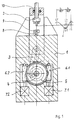
- FIG. 1 is a schematic illustration of a Press according to the invention in a sectional view, with only the drive one Upper stamp unit 2 (i.e. the upper bear of the press in which the upper stamp unit is stored) is reproduced.
- This upper stamp unit 2 depending on the shape one or more upper punches of the pressed body to be produced are held, is slidably mounted in a machine frame 1 of the press.
- the compact is in that of a die 9 and one in the machine frame 1 of the press e.g. firmly Supported lower stamp unit 8 enclosed mold cavity generated in the the upper punch or plunges when pressing.
- One is expedient mechanical adjusting device 10 is provided, via which the output and End position of the upper punch unit 2 are adjustable.
- an electronic rotary encoder On the crankshaft 4 is housed an electronic rotary encoder, not shown, with its The current position of the upper stamp unit 2 can be detected indirectly.
- a hydraulic pressure system is provided, which is also not shown in detail and also the supply of additional hydraulics driven press tool parts (e.g. die, lower punch unit or Tool adapter). All movements of the press parts are carried out by an electronic control not shown in Fig. 1 performed the Valves and pumps of the hydraulic system based on the measured values of the Rotary angle encoder or the direct measuring systems used controls.
- the eccentric crank drive in the lower Provides part of the machine frame 1, it should be in the practical execution of a Press according to the invention may be more advantageous, the eccentric crank drive to be arranged above the upper punch unit 2, i.e. in the top of the press. This does not change the basic functionality.
- the two screws of the worm drives 6.1 and 6.2 are over the Hydraulic motors 7.1, 7.2 with the one supported by a hydraulic pump Hydraulic fluid acted on and effect according to the gear ratio Worm drives 6.1, 6.2 a torque on the gear 5 and a corresponding one Rotational movement of the crankshaft 4.
- the electronic control is designed so that one by switching the direction of rotation of the hydraulic motors 7.1, 7.2 reversing rotary movement on the crankshaft 4 over an angular range of z. B. gives 120 °. With appropriate selection of the number of revolutions of the Hydraulic motors 7.1, 7.2 move the short drive to the lower area Dead center.
- the control of the press can be set up so that depending on Requires a press end position beyond the bottom dead center of the connecting rod 3 becomes.
- the absolute dead center of the press position is once in the actual work cycle and then again at the beginning of the "empty cycle" run over so that a double pressure is effected.
- By shortening the rotation the crankshaft to an area well below 180 ° becomes the need avoided the relatively time-consuming valley and / or the mountain top of the sinusoidal Having to go through the movement curve completely. This can easily be done save about 30-50% of the cycle time.
- Reversing operation in the sense of the present invention, but not in presses with the usual eccentric drive that performs complete complete rotations regularly.
- the press thus advantageously combines a slow work trip with a large one Pressing force and a quick return trip with less force.
- the drive power of the Press can be much more uniform in this way over the duration of the press cycle be used than is the case with a conventional hydraulic press.
- the parallel or series connection also be maintained unchanged throughout the press cycle, the latter is particularly recommended for achieving high production output Pressed parts with a comparatively low height, for the lower press forces are sufficient.
- the press according to the invention can also be used like a conventional mechanical press in continuous operation, i.e. without reversing the Operate drive motors. This still has the advantage of a light one Adaptability of the working speed.
- an electronic control is provided, which is a path control with free programmable controlled positions and speeds allowed.
- the sinusoidal course of the path covered by the upper stamp unit 2 as a function of time is shown at the top right in FIG.
- the crankshaft rotation is 180 °, the upper punch unit 2 moving from top dead center OT to bottom dead center UT.
- the time required for this (compression stroke) is denoted by t v . Since the subsequent return movement from bottom dead center UT to top dead center OT is not carried out in hydraulic parallel connection, but in series connection of hydraulic motors 7.1, 7.2, the crankshaft 4 rotates equally, but the time required is due to the constant delivery flow of the hydraulic pump has become smaller and is only t r .
- the second part of the sine curve is therefore compressed accordingly in the direction of the time axis.
- the dash-dotted lines and the +/- signs indicate in the graphic that the end position of the upper punch unit can be varied in the positive or negative direction in the area of the dead center.
- the part of the work cycle in which the powder is compressed in the press mold is designated by A.
- Figure 2 are in the sense of an embodiment depending on the crank angle ⁇ of the eccentric crank drive, the courses of some characteristic values of an inventive Press reproduced. Only the section in the area of Crank angle ⁇ from 130 ° to about 180 ° (bottom dead center) reproduced.
- the selected example refers to a press in which the crank angle range from 130 ° to 180 ° corresponds to a travel of the upper punch unit by 40 mm.
- the curve s of the travel path in FIG. 2 thus gives the distance between the Upper stamp unit from the bottom dead center. This travel distance corresponds approximately the actual pressing process in the press, i.e. the phase of powder compaction.
- the curve labeled F shows the course of the actual pressing force at one representative press body again, which is the maximum that can be processed by the press Height. With increasing powder compaction, this pressing force F increases approximately a crank angle ⁇ of 140 ° strongly up to a value of 2340 kN in the lower Dead center.
- the torque M d associated with the respective pressing force on the crankshaft has a size of 7125 Nm under the given dimensional relationships of the press at a crank angle of 140 °.
- the torque then rises steeply and reaches its maximum at around 160 ° with a value of 45500 Nm.
- the maximum pressing force is 1225 kN. After reaching the maximum, the torque drops sharply as the crank angle ⁇ increases and is zero at bottom dead center, while the pressing force reaches its maximum value.
- the torque on the crankshaft is directly proportional to the torque of the hydraulic motors and thus to the hydraulic pressure.
- the tangential shaft on gear 5 is at the maximum torque (45500 Nm) only 364 KN, while the actual pressing force F is 1225 kN.
- the maximum possible Force transmission V in FIG. 2 is also a function of the crank angle ⁇ shown. Especially in the area of the last degrees of angle before reaching the bottom dead center there is a highly progressive increase in power transmission V.
- the drive proposed by the invention is particularly advantageous for the Upper punch unit used in powder presses, their other levels of movement (Die, tool adapter) are also hydraulically driven and some have a common main drive motor for the hydraulics.
- This is special expedient because the power requirement for the upper stamp unit and As a rule, the matrix does not line up at the same time but one after the other larger momentum of a central drive to reduce the peak power the upper punch unit in the range of a crank angle of approximately 160 ° and later on bottom dead center (crank angle 180 °) is beneficial when tearing the die.
- the Press according to the invention provides a sinusoidal movement and force curve, enables high accuracy in the compacts to be produced, has one high efficiency, is extremely flexible with regard to the producible parts, increased the production performance clearly and brings a significant advance in the Manufacturing technology.
Landscapes
- Engineering & Computer Science (AREA)
- Mechanical Engineering (AREA)
- Press Drives And Press Lines (AREA)
- Presses And Accessory Devices Thereof (AREA)
- Powder Metallurgy (AREA)
Applications Claiming Priority (2)
| Application Number | Priority Date | Filing Date | Title |
|---|---|---|---|
| DE19947689 | 1999-09-24 | ||
| DE19947689A DE19947689C2 (de) | 1999-09-24 | 1999-09-24 | Presse mit Exzenterkurbeltrieb für Oberstempeleinheit und Betriebsverfahren |
Publications (3)
| Publication Number | Publication Date |
|---|---|
| EP1086802A2 true EP1086802A2 (fr) | 2001-03-28 |
| EP1086802A3 EP1086802A3 (fr) | 2002-01-16 |
| EP1086802B1 EP1086802B1 (fr) | 2006-11-02 |
Family
ID=7924391
Family Applications (1)
| Application Number | Title | Priority Date | Filing Date |
|---|---|---|---|
| EP00250306A Expired - Lifetime EP1086802B1 (fr) | 1999-09-24 | 2000-09-15 | Presse avec entraînement à vilebrequin pour le poinçon supérieur et son procédé de fonctionnement |
Country Status (9)
| Country | Link |
|---|---|
| US (1) | US6564704B1 (fr) |
| EP (1) | EP1086802B1 (fr) |
| JP (1) | JP3723727B2 (fr) |
| CN (1) | CN1187184C (fr) |
| AT (1) | ATE344132T1 (fr) |
| CA (1) | CA2320498C (fr) |
| DE (2) | DE19947689C2 (fr) |
| ES (1) | ES2270788T3 (fr) |
| RU (1) | RU2244627C2 (fr) |
Cited By (5)
| Publication number | Priority date | Publication date | Assignee | Title |
|---|---|---|---|---|
| EP1281507A3 (fr) * | 2001-08-02 | 2003-03-19 | Komage-Gellner Maschinenfabrik KG | Presse à excentrique et procédé pour actionner une presse à excentrique |
| EP1281508A3 (fr) * | 2001-08-02 | 2003-03-19 | Komage-Gellner Maschinenfabrik KG | Presse et procédé pour actionner une presse |
| NL2000449C2 (nl) * | 2007-01-22 | 2008-07-23 | Fico Bv | Werkwijze en inrichting voor het in een pers mechanisch bewerken van halfgeleider producten. |
| CN100410064C (zh) * | 2006-10-25 | 2008-08-13 | 南京东部精密机械有限公司 | 中小型曲柄滑块式全自动干粉压机 |
| CN104960230A (zh) * | 2015-06-25 | 2015-10-07 | 刘海明 | 一种自动切棒的制棒机 |
Families Citing this family (6)
| Publication number | Priority date | Publication date | Assignee | Title |
|---|---|---|---|---|
| US6506118B1 (en) * | 2001-08-24 | 2003-01-14 | Igt | Gaming device having improved award offer bonus scheme |
| RU2446949C2 (ru) * | 2008-01-17 | 2012-04-10 | Михаил Алексеевич Паюсов | Пресс брикетный |
| CN102179953B (zh) * | 2011-03-09 | 2014-10-29 | 东莞华中科技大学制造工程研究院 | 压力机下死点的精确调整方法 |
| FR3021805B1 (fr) * | 2014-05-27 | 2019-05-03 | Commissariat A L'energie Atomique Et Aux Energies Alternatives | Presse pour mettre en forme des pastilles dans un environnement restreint et hostile et procede d'assemblage de la presse |
| CN104741606A (zh) * | 2015-03-31 | 2015-07-01 | 龙岩市泰美耐磨合金有限公司 | 一种金属粉末压坯成型装置 |
| EP3536493A1 (fr) * | 2018-03-05 | 2019-09-11 | Arcofil S.A. | Presse électrique à moteur torque |
Family Cites Families (14)
| Publication number | Priority date | Publication date | Assignee | Title |
|---|---|---|---|---|
| US3124019A (en) * | 1964-03-10 | Cold forming machine | ||
| CH271725A (de) * | 1948-08-24 | 1950-11-15 | May Otto Ing Dr | Kniehebelpresse. |
| US2784665A (en) * | 1951-10-06 | 1957-03-12 | Danly Mach Specialties Inc | Safety knuckle joint press |
| FR1575101A (fr) * | 1967-09-27 | 1969-07-18 | ||
| JPS5481574A (en) * | 1977-12-10 | 1979-06-29 | Hiroyasu Shiokawa | Machine press |
| JPS58103996A (ja) * | 1981-12-17 | 1983-06-21 | Aida Eng Ltd | C形フレ−ムプレス |
| DE3580801D1 (de) * | 1984-07-11 | 1991-01-17 | Chiyoda Tech & Ind | Verfahren und vorrichtung zum einsetzen von strukturierten matrizen und pressplatten in schnellpressen fuer betonwaren. |
| DE3788349T2 (de) * | 1986-12-29 | 1994-05-11 | Mitoshi Ishii | Servolenkvorrichtung fuer eine presse. |
| SU1620328A1 (ru) * | 1988-05-27 | 1991-01-15 | Специальное Конструкторское Бюро Кузнечно-Прессовых Машин И Автоматических Линий | Вертикальный пресс дл производства изделий из металлических порошков |
| DE4114880A1 (de) * | 1990-05-09 | 1991-11-14 | Komage Gellner & Co Maschinenf | Presse zum verpressen pulverfoermiger massen |
| US5198241A (en) * | 1991-01-29 | 1993-03-30 | Spex Industries, Inc. | Apparatus for preparation of samples for spectrographic analysis |
| US5588344A (en) * | 1994-06-13 | 1996-12-31 | Murata Machinery, Ltd. | Electric servo motor punch press ram drive |
| US5669257A (en) * | 1994-12-28 | 1997-09-23 | Yazaki Corporation | Method of crimping terminal and apparatus for the same |
| DE29917742U1 (de) * | 1998-10-23 | 2000-01-13 | Mannesmann AG, 40213 Düsseldorf | Presse mit Exzenterkurbeltrieb für Oberstempeleinheit |
-
1999
- 1999-09-24 DE DE19947689A patent/DE19947689C2/de not_active Expired - Fee Related
-
2000
- 2000-09-15 ES ES00250306T patent/ES2270788T3/es not_active Expired - Lifetime
- 2000-09-15 DE DE50013679T patent/DE50013679D1/de not_active Expired - Lifetime
- 2000-09-15 EP EP00250306A patent/EP1086802B1/fr not_active Expired - Lifetime
- 2000-09-15 AT AT00250306T patent/ATE344132T1/de active
- 2000-09-22 CA CA002320498A patent/CA2320498C/fr not_active Expired - Fee Related
- 2000-09-22 RU RU2000124311/02A patent/RU2244627C2/ru not_active IP Right Cessation
- 2000-09-22 CN CNB001288202A patent/CN1187184C/zh not_active Expired - Fee Related
- 2000-09-25 US US09/668,872 patent/US6564704B1/en not_active Expired - Lifetime
- 2000-09-25 JP JP2000289906A patent/JP3723727B2/ja not_active Expired - Fee Related
Cited By (5)
| Publication number | Priority date | Publication date | Assignee | Title |
|---|---|---|---|---|
| EP1281507A3 (fr) * | 2001-08-02 | 2003-03-19 | Komage-Gellner Maschinenfabrik KG | Presse à excentrique et procédé pour actionner une presse à excentrique |
| EP1281508A3 (fr) * | 2001-08-02 | 2003-03-19 | Komage-Gellner Maschinenfabrik KG | Presse et procédé pour actionner une presse |
| CN100410064C (zh) * | 2006-10-25 | 2008-08-13 | 南京东部精密机械有限公司 | 中小型曲柄滑块式全自动干粉压机 |
| NL2000449C2 (nl) * | 2007-01-22 | 2008-07-23 | Fico Bv | Werkwijze en inrichting voor het in een pers mechanisch bewerken van halfgeleider producten. |
| CN104960230A (zh) * | 2015-06-25 | 2015-10-07 | 刘海明 | 一种自动切棒的制棒机 |
Also Published As
| Publication number | Publication date |
|---|---|
| ATE344132T1 (de) | 2006-11-15 |
| JP3723727B2 (ja) | 2005-12-07 |
| CN1187184C (zh) | 2005-02-02 |
| DE50013679D1 (de) | 2006-12-14 |
| RU2244627C2 (ru) | 2005-01-20 |
| US6564704B1 (en) | 2003-05-20 |
| ES2270788T3 (es) | 2007-04-16 |
| CA2320498A1 (fr) | 2001-03-24 |
| DE19947689C2 (de) | 2002-02-07 |
| CN1289676A (zh) | 2001-04-04 |
| EP1086802A3 (fr) | 2002-01-16 |
| CA2320498C (fr) | 2008-06-10 |
| EP1086802B1 (fr) | 2006-11-02 |
| DE19947689A1 (de) | 2001-04-19 |
| JP2001129692A (ja) | 2001-05-15 |
Similar Documents
| Publication | Publication Date | Title |
|---|---|---|
| EP0773846B1 (fr) | Dispositif de production de comprimes en metallurgie | |
| EP1318906B1 (fr) | Dispositif de commande pour une presse hydraulique et procede pour son fonctionnement | |
| EP2480405B1 (fr) | Entrainement hydraulique precontraint dote d'une pompe a vitesse variable | |
| DE19947689C2 (de) | Presse mit Exzenterkurbeltrieb für Oberstempeleinheit und Betriebsverfahren | |
| WO2011045303A2 (fr) | Presse à poudre | |
| DE3626455A1 (de) | Spindelpresse | |
| DE19646913A1 (de) | Hydraulische Antriebseinheit einer Presse und eine Taumelscheiben-Axialkolbenpumpe mit variabler Kapazität zur Verwendung mit dieser Vorrichtung | |
| EP2911871B1 (fr) | Dispositif d'entraînement | |
| DE69622636T2 (de) | Vorrichtung zum Formpressen | |
| DE2131013C2 (de) | Ziehpresse | |
| EP2008800A1 (fr) | Dispositif d'actionnement pour un automate de presse, de découpe ou de déformage | |
| DE4310310A1 (de) | Einpreßaggregat | |
| WO2000020192A1 (fr) | Presse pour produire des corps moules | |
| EP3774316B1 (fr) | Entraînement de presse à récupération d'énergie | |
| EP2316639B1 (fr) | Procédé et dispositif de réglage de l'entraînement de presses à balles | |
| DE3323428C2 (fr) | ||
| EP1120236B1 (fr) | Dispositif d'avance pour le coulisseau supérieur d'une presse | |
| DE29917742U1 (de) | Presse mit Exzenterkurbeltrieb für Oberstempeleinheit | |
| EP0829318B1 (fr) | Procédé de réglage de fréquence de la course du coulisseau dans une presse de forgeage et presse de forgeage pour la mise en oeuvre de ce procédé | |
| DE29917531U1 (de) | Presse mit Exzenterkurbeltrieb für Oberstempeleinheit | |
| DE29917654U1 (de) | Presse mit Exzenterkurbeltrieb für Oberstempeleinheit | |
| DE2202156B2 (de) | Haushaltmüllpresse mit geradegeführtem Hebelmechanismus zur Stempelbewegung | |
| EP2483065A1 (fr) | Procédé pour déplacer une unité de façonnage d'une machine | |
| DE4410004C2 (de) | Vorrichtung zum Pressen oder hydraulische Hubeinrichtung | |
| DE10138664A1 (de) | Presse und Verfahren zum Betreiben der Presse |
Legal Events
| Date | Code | Title | Description |
|---|---|---|---|
| PUAI | Public reference made under article 153(3) epc to a published international application that has entered the european phase |
Free format text: ORIGINAL CODE: 0009012 |
|
| AK | Designated contracting states |
Kind code of ref document: A2 Designated state(s): AT BE CH CY DE DK ES FI FR GB GR IE IT LI LU MC NL PT SE |
|
| AX | Request for extension of the european patent |
Free format text: AL;LT;LV;MK;RO;SI |
|
| PUAL | Search report despatched |
Free format text: ORIGINAL CODE: 0009013 |
|
| AK | Designated contracting states |
Kind code of ref document: A3 Designated state(s): AT BE CH CY DE DK ES FI FR GB GR IE IT LI LU MC NL PT SE |
|
| AX | Request for extension of the european patent |
Free format text: AL;LT;LV;MK;RO;SI |
|
| 17P | Request for examination filed |
Effective date: 20020611 |
|
| AKX | Designation fees paid |
Free format text: AT BE CH CY DE DK ES FI FR GB GR IE IT LI LU MC NL PT SE |
|
| 17Q | First examination report despatched |
Effective date: 20040419 |
|
| GRAP | Despatch of communication of intention to grant a patent |
Free format text: ORIGINAL CODE: EPIDOSNIGR1 |
|
| GRAS | Grant fee paid |
Free format text: ORIGINAL CODE: EPIDOSNIGR3 |
|
| GRAA | (expected) grant |
Free format text: ORIGINAL CODE: 0009210 |
|
| AK | Designated contracting states |
Kind code of ref document: B1 Designated state(s): AT BE CH CY DE DK ES FI FR GB GR IE IT LI LU MC NL PT SE |
|
| PG25 | Lapsed in a contracting state [announced via postgrant information from national office to epo] |
Ref country code: IE Free format text: LAPSE BECAUSE OF FAILURE TO SUBMIT A TRANSLATION OF THE DESCRIPTION OR TO PAY THE FEE WITHIN THE PRESCRIBED TIME-LIMIT Effective date: 20061102 Ref country code: FI Free format text: LAPSE BECAUSE OF FAILURE TO SUBMIT A TRANSLATION OF THE DESCRIPTION OR TO PAY THE FEE WITHIN THE PRESCRIBED TIME-LIMIT Effective date: 20061102 Ref country code: NL Free format text: LAPSE BECAUSE OF FAILURE TO SUBMIT A TRANSLATION OF THE DESCRIPTION OR TO PAY THE FEE WITHIN THE PRESCRIBED TIME-LIMIT Effective date: 20061102 |
|
| REG | Reference to a national code |
Ref country code: GB Ref legal event code: FG4D Free format text: NOT ENGLISH |
|
| REG | Reference to a national code |
Ref country code: IE Ref legal event code: FG4D Free format text: LANGUAGE OF EP DOCUMENT: GERMAN |
|
| REG | Reference to a national code |
Ref country code: CH Ref legal event code: EP Ref country code: CH Ref legal event code: NV Representative=s name: E. BLUM & CO. PATENTANWAELTE |
|
| REF | Corresponds to: |
Ref document number: 50013679 Country of ref document: DE Date of ref document: 20061214 Kind code of ref document: P |
|
| REG | Reference to a national code |
Ref country code: SE Ref legal event code: TRGR |
|
| PG25 | Lapsed in a contracting state [announced via postgrant information from national office to epo] |
Ref country code: DK Free format text: LAPSE BECAUSE OF FAILURE TO SUBMIT A TRANSLATION OF THE DESCRIPTION OR TO PAY THE FEE WITHIN THE PRESCRIBED TIME-LIMIT Effective date: 20070202 |
|
| PG25 | Lapsed in a contracting state [announced via postgrant information from national office to epo] |
Ref country code: PT Free format text: LAPSE BECAUSE OF FAILURE TO SUBMIT A TRANSLATION OF THE DESCRIPTION OR TO PAY THE FEE WITHIN THE PRESCRIBED TIME-LIMIT Effective date: 20070402 |
|
| REG | Reference to a national code |
Ref country code: ES Ref legal event code: FG2A Ref document number: 2270788 Country of ref document: ES Kind code of ref document: T3 |
|
| NLV1 | Nl: lapsed or annulled due to failure to fulfill the requirements of art. 29p and 29m of the patents act | ||
| GBV | Gb: ep patent (uk) treated as always having been void in accordance with gb section 77(7)/1977 [no translation filed] |
Effective date: 20061102 |
|
| EN | Fr: translation not filed | ||
| REG | Reference to a national code |
Ref country code: IE Ref legal event code: FD4D |
|
| PLBE | No opposition filed within time limit |
Free format text: ORIGINAL CODE: 0009261 |
|
| STAA | Information on the status of an ep patent application or granted ep patent |
Free format text: STATUS: NO OPPOSITION FILED WITHIN TIME LIMIT |
|
| 26N | No opposition filed |
Effective date: 20070803 |
|
| REG | Reference to a national code |
Ref country code: CH Ref legal event code: PFA Owner name: SMS DEMAG AG Free format text: SMS DEMAG AG#EDUARD-SCHLOEMANN-STRASSE 4#40237 DUESSELDORF (DE) -TRANSFER TO- SMS DEMAG AG#EDUARD-SCHLOEMANN-STRASSE 4#40237 DUESSELDORF (DE) |
|
| PG25 | Lapsed in a contracting state [announced via postgrant information from national office to epo] |
Ref country code: GB Free format text: LAPSE BECAUSE OF FAILURE TO SUBMIT A TRANSLATION OF THE DESCRIPTION OR TO PAY THE FEE WITHIN THE PRESCRIBED TIME-LIMIT Effective date: 20061102 |
|
| BERE | Be: lapsed |
Owner name: SMS DEMAG AG Effective date: 20070930 |
|
| PG25 | Lapsed in a contracting state [announced via postgrant information from national office to epo] |
Ref country code: MC Free format text: LAPSE BECAUSE OF NON-PAYMENT OF DUE FEES Effective date: 20070930 Ref country code: FR Free format text: LAPSE BECAUSE OF FAILURE TO SUBMIT A TRANSLATION OF THE DESCRIPTION OR TO PAY THE FEE WITHIN THE PRESCRIBED TIME-LIMIT Effective date: 20070615 Ref country code: GR Free format text: LAPSE BECAUSE OF FAILURE TO SUBMIT A TRANSLATION OF THE DESCRIPTION OR TO PAY THE FEE WITHIN THE PRESCRIBED TIME-LIMIT Effective date: 20070203 |
|
| PG25 | Lapsed in a contracting state [announced via postgrant information from national office to epo] |
Ref country code: BE Free format text: LAPSE BECAUSE OF NON-PAYMENT OF DUE FEES Effective date: 20070930 |
|
| PG25 | Lapsed in a contracting state [announced via postgrant information from national office to epo] |
Ref country code: FR Free format text: LAPSE BECAUSE OF FAILURE TO SUBMIT A TRANSLATION OF THE DESCRIPTION OR TO PAY THE FEE WITHIN THE PRESCRIBED TIME-LIMIT Effective date: 20061102 |
|
| PG25 | Lapsed in a contracting state [announced via postgrant information from national office to epo] |
Ref country code: LU Free format text: LAPSE BECAUSE OF NON-PAYMENT OF DUE FEES Effective date: 20070915 Ref country code: CY Free format text: LAPSE BECAUSE OF FAILURE TO SUBMIT A TRANSLATION OF THE DESCRIPTION OR TO PAY THE FEE WITHIN THE PRESCRIBED TIME-LIMIT Effective date: 20061102 |
|
| PGFP | Annual fee paid to national office [announced via postgrant information from national office to epo] |
Ref country code: CH Payment date: 20110923 Year of fee payment: 12 |
|
| PGFP | Annual fee paid to national office [announced via postgrant information from national office to epo] |
Ref country code: SE Payment date: 20120919 Year of fee payment: 13 |
|
| PGFP | Annual fee paid to national office [announced via postgrant information from national office to epo] |
Ref country code: ES Payment date: 20120926 Year of fee payment: 13 |
|
| PGFP | Annual fee paid to national office [announced via postgrant information from national office to epo] |
Ref country code: IT Payment date: 20120926 Year of fee payment: 13 |
|
| PGFP | Annual fee paid to national office [announced via postgrant information from national office to epo] |
Ref country code: AT Payment date: 20130911 Year of fee payment: 14 |
|
| REG | Reference to a national code |
Ref country code: SE Ref legal event code: EUG |
|
| PG25 | Lapsed in a contracting state [announced via postgrant information from national office to epo] |
Ref country code: SE Free format text: LAPSE BECAUSE OF NON-PAYMENT OF DUE FEES Effective date: 20130916 |
|
| REG | Reference to a national code |
Ref country code: CH Ref legal event code: PL |
|
| PG25 | Lapsed in a contracting state [announced via postgrant information from national office to epo] |
Ref country code: LI Free format text: LAPSE BECAUSE OF NON-PAYMENT OF DUE FEES Effective date: 20130930 Ref country code: CH Free format text: LAPSE BECAUSE OF NON-PAYMENT OF DUE FEES Effective date: 20130930 |
|
| PG25 | Lapsed in a contracting state [announced via postgrant information from national office to epo] |
Ref country code: IT Free format text: LAPSE BECAUSE OF NON-PAYMENT OF DUE FEES Effective date: 20130915 |
|
| REG | Reference to a national code |
Ref country code: ES Ref legal event code: FD2A Effective date: 20141016 |
|
| PG25 | Lapsed in a contracting state [announced via postgrant information from national office to epo] |
Ref country code: ES Free format text: LAPSE BECAUSE OF NON-PAYMENT OF DUE FEES Effective date: 20130916 |
|
| REG | Reference to a national code |
Ref country code: AT Ref legal event code: MM01 Ref document number: 344132 Country of ref document: AT Kind code of ref document: T Effective date: 20140915 |
|
| PG25 | Lapsed in a contracting state [announced via postgrant information from national office to epo] |
Ref country code: AT Free format text: LAPSE BECAUSE OF NON-PAYMENT OF DUE FEES Effective date: 20140915 |
|
| REG | Reference to a national code |
Ref country code: DE Ref legal event code: R082 Ref document number: 50013679 Country of ref document: DE Representative=s name: ANWALTSKANZLEI MEISSNER & MEISSNER, DE Ref country code: DE Ref legal event code: R081 Ref document number: 50013679 Country of ref document: DE Owner name: SMS GROUP GMBH, DE Free format text: FORMER OWNER: SMS SIEMAG AKTIENGESELLSCHAFT, 40237 DUESSELDORF, DE |
|
| PGFP | Annual fee paid to national office [announced via postgrant information from national office to epo] |
Ref country code: DE Payment date: 20160921 Year of fee payment: 17 |
|
| REG | Reference to a national code |
Ref country code: DE Ref legal event code: R119 Ref document number: 50013679 Country of ref document: DE |
|
| PG25 | Lapsed in a contracting state [announced via postgrant information from national office to epo] |
Ref country code: DE Free format text: LAPSE BECAUSE OF NON-PAYMENT OF DUE FEES Effective date: 20180404 |