EP1087455A2 - Réservoir contenant du combustible liquide pour pile à combustible et pile à combustible - Google Patents
Réservoir contenant du combustible liquide pour pile à combustible et pile à combustible Download PDFInfo
- Publication number
- EP1087455A2 EP1087455A2 EP00307819A EP00307819A EP1087455A2 EP 1087455 A2 EP1087455 A2 EP 1087455A2 EP 00307819 A EP00307819 A EP 00307819A EP 00307819 A EP00307819 A EP 00307819A EP 1087455 A2 EP1087455 A2 EP 1087455A2
- Authority
- EP
- European Patent Office
- Prior art keywords
- liquid fuel
- liquid
- fuel
- fuel tank
- tank
- Prior art date
- Legal status (The legal status is an assumption and is not a legal conclusion. Google has not performed a legal analysis and makes no representation as to the accuracy of the status listed.)
- Withdrawn
Links
- 239000000446 fuel Substances 0.000 title claims abstract description 545
- 239000007788 liquid Substances 0.000 title claims abstract description 451
- 239000002828 fuel tank Substances 0.000 claims abstract description 219
- 210000004027 cell Anatomy 0.000 claims abstract description 168
- 210000005056 cell body Anatomy 0.000 claims abstract description 100
- 230000007246 mechanism Effects 0.000 claims abstract description 44
- 239000012528 membrane Substances 0.000 claims abstract description 19
- 230000001590 oxidative effect Effects 0.000 claims abstract description 18
- 239000007800 oxidant agent Substances 0.000 claims abstract description 15
- 230000009471 action Effects 0.000 claims abstract description 12
- 239000003792 electrolyte Substances 0.000 claims abstract description 12
- 239000000463 material Substances 0.000 claims description 85
- 230000037361 pathway Effects 0.000 claims description 39
- 238000010248 power generation Methods 0.000 claims description 21
- 238000003860 storage Methods 0.000 claims description 13
- 239000011358 absorbing material Substances 0.000 claims description 11
- 239000012780 transparent material Substances 0.000 claims description 3
- 238000010276 construction Methods 0.000 description 38
- OKKJLVBELUTLKV-UHFFFAOYSA-N Methanol Chemical compound OC OKKJLVBELUTLKV-UHFFFAOYSA-N 0.000 description 36
- 239000007789 gas Substances 0.000 description 33
- 230000008016 vaporization Effects 0.000 description 14
- XLYOFNOQVPJJNP-UHFFFAOYSA-N water Substances O XLYOFNOQVPJJNP-UHFFFAOYSA-N 0.000 description 10
- OKTJSMMVPCPJKN-UHFFFAOYSA-N Carbon Chemical compound [C] OKTJSMMVPCPJKN-UHFFFAOYSA-N 0.000 description 9
- 229910052799 carbon Inorganic materials 0.000 description 9
- -1 polyethylene Polymers 0.000 description 8
- 230000008859 change Effects 0.000 description 7
- 239000011259 mixed solution Substances 0.000 description 7
- 239000011148 porous material Substances 0.000 description 7
- 239000011347 resin Substances 0.000 description 6
- 229920005989 resin Polymers 0.000 description 6
- 238000012360 testing method Methods 0.000 description 6
- 238000001704 evaporation Methods 0.000 description 5
- 238000000034 method Methods 0.000 description 5
- 230000000630 rising effect Effects 0.000 description 5
- 229920006395 saturated elastomer Polymers 0.000 description 5
- 238000007789 sealing Methods 0.000 description 5
- CURLTUGMZLYLDI-UHFFFAOYSA-N Carbon dioxide Chemical compound O=C=O CURLTUGMZLYLDI-UHFFFAOYSA-N 0.000 description 4
- LFQSCWFLJHTTHZ-UHFFFAOYSA-N Ethanol Chemical compound CCO LFQSCWFLJHTTHZ-UHFFFAOYSA-N 0.000 description 4
- VYPSYNLAJGMNEJ-UHFFFAOYSA-N Silicium dioxide Chemical compound O=[Si]=O VYPSYNLAJGMNEJ-UHFFFAOYSA-N 0.000 description 4
- 230000008020 evaporation Effects 0.000 description 4
- RTZKZFJDLAIYFH-UHFFFAOYSA-N Diethyl ether Chemical compound CCOCC RTZKZFJDLAIYFH-UHFFFAOYSA-N 0.000 description 3
- 239000004698 Polyethylene Substances 0.000 description 3
- 239000004743 Polypropylene Substances 0.000 description 3
- 239000003054 catalyst Substances 0.000 description 3
- 230000000052 comparative effect Effects 0.000 description 3
- 238000007667 floating Methods 0.000 description 3
- 230000006870 function Effects 0.000 description 3
- 239000000203 mixture Substances 0.000 description 3
- 230000035699 permeability Effects 0.000 description 3
- 239000012466 permeate Substances 0.000 description 3
- 229920000515 polycarbonate Polymers 0.000 description 3
- 239000004417 polycarbonate Substances 0.000 description 3
- 229920000573 polyethylene Polymers 0.000 description 3
- 229920001155 polypropylene Polymers 0.000 description 3
- 238000009834 vaporization Methods 0.000 description 3
- XKRFYHLGVUSROY-UHFFFAOYSA-N Argon Chemical compound [Ar] XKRFYHLGVUSROY-UHFFFAOYSA-N 0.000 description 2
- OAKJQQAXSVQMHS-UHFFFAOYSA-N Hydrazine Chemical compound NN OAKJQQAXSVQMHS-UHFFFAOYSA-N 0.000 description 2
- PNEYBMLMFCGWSK-UHFFFAOYSA-N aluminium oxide Inorganic materials [O-2].[O-2].[O-2].[Al+3].[Al+3] PNEYBMLMFCGWSK-UHFFFAOYSA-N 0.000 description 2
- 229910002092 carbon dioxide Inorganic materials 0.000 description 2
- 239000001569 carbon dioxide Substances 0.000 description 2
- 229920002678 cellulose Polymers 0.000 description 2
- 239000000919 ceramic Substances 0.000 description 2
- 230000001419 dependent effect Effects 0.000 description 2
- 239000000975 dye Substances 0.000 description 2
- 229920006351 engineering plastic Polymers 0.000 description 2
- 239000004744 fabric Substances 0.000 description 2
- NBVXSUQYWXRMNV-UHFFFAOYSA-N fluoromethane Chemical compound FC NBVXSUQYWXRMNV-UHFFFAOYSA-N 0.000 description 2
- 230000005484 gravity Effects 0.000 description 2
- 239000011344 liquid material Substances 0.000 description 2
- 238000004519 manufacturing process Methods 0.000 description 2
- 239000002184 metal Substances 0.000 description 2
- 239000000123 paper Substances 0.000 description 2
- 239000005011 phenolic resin Substances 0.000 description 2
- 229920002492 poly(sulfone) Polymers 0.000 description 2
- 229920000767 polyaniline Polymers 0.000 description 2
- 229920002480 polybenzimidazole Polymers 0.000 description 2
- 229920000728 polyester Polymers 0.000 description 2
- 229920001721 polyimide Polymers 0.000 description 2
- 229920006327 polystyrene foam Polymers 0.000 description 2
- 229920001021 polysulfide Polymers 0.000 description 2
- 239000005077 polysulfide Substances 0.000 description 2
- 150000008117 polysulfides Polymers 0.000 description 2
- 229920002635 polyurethane Polymers 0.000 description 2
- 239000004814 polyurethane Substances 0.000 description 2
- 230000036647 reaction Effects 0.000 description 2
- 239000000377 silicon dioxide Substances 0.000 description 2
- 239000011343 solid material Substances 0.000 description 2
- 239000000243 solution Substances 0.000 description 2
- 239000000126 substance Substances 0.000 description 2
- 238000004381 surface treatment Methods 0.000 description 2
- 229920001187 thermosetting polymer Polymers 0.000 description 2
- 229920002554 vinyl polymer Polymers 0.000 description 2
- KXGFMDJXCMQABM-UHFFFAOYSA-N 2-methoxy-6-methylphenol Chemical compound [CH]OC1=CC=CC([CH])=C1O KXGFMDJXCMQABM-UHFFFAOYSA-N 0.000 description 1
- IJGRMHOSHXDMSA-UHFFFAOYSA-N Atomic nitrogen Chemical compound N#N IJGRMHOSHXDMSA-UHFFFAOYSA-N 0.000 description 1
- YCKRFDGAMUMZLT-UHFFFAOYSA-N Fluorine atom Chemical compound [F] YCKRFDGAMUMZLT-UHFFFAOYSA-N 0.000 description 1
- 239000004642 Polyimide Substances 0.000 description 1
- 229910002848 Pt–Ru Inorganic materials 0.000 description 1
- 239000004809 Teflon Substances 0.000 description 1
- 229920006362 Teflon® Polymers 0.000 description 1
- 150000001298 alcohols Chemical class 0.000 description 1
- 229910052786 argon Inorganic materials 0.000 description 1
- 230000003915 cell function Effects 0.000 description 1
- 239000001913 cellulose Substances 0.000 description 1
- 239000012461 cellulose resin Substances 0.000 description 1
- 238000012790 confirmation Methods 0.000 description 1
- 230000006866 deterioration Effects 0.000 description 1
- 229910001873 dinitrogen Inorganic materials 0.000 description 1
- 230000000694 effects Effects 0.000 description 1
- 150000002170 ethers Chemical class 0.000 description 1
- 229910052731 fluorine Inorganic materials 0.000 description 1
- 239000011737 fluorine Substances 0.000 description 1
- 229920002313 fluoropolymer Polymers 0.000 description 1
- UQSQSQZYBQSBJZ-UHFFFAOYSA-N fluorosulfonic acid Chemical compound OS(F)(=O)=O UQSQSQZYBQSBJZ-UHFFFAOYSA-N 0.000 description 1
- 238000007731 hot pressing Methods 0.000 description 1
- 239000011261 inert gas Substances 0.000 description 1
- 238000010030 laminating Methods 0.000 description 1
- 230000014759 maintenance of location Effects 0.000 description 1
- 230000004048 modification Effects 0.000 description 1
- 238000012986 modification Methods 0.000 description 1
- 230000000414 obstructive effect Effects 0.000 description 1
- 239000003960 organic solvent Substances 0.000 description 1
- 229920001568 phenolic resin Polymers 0.000 description 1
- 229920006289 polycarbonate film Polymers 0.000 description 1
- 239000004645 polyester resin Substances 0.000 description 1
- 229920001343 polytetrafluoroethylene Polymers 0.000 description 1
- 239000004810 polytetrafluoroethylene Substances 0.000 description 1
- 238000012545 processing Methods 0.000 description 1
- BDERNNFJNOPAEC-UHFFFAOYSA-N propan-1-ol Chemical compound CCCO BDERNNFJNOPAEC-UHFFFAOYSA-N 0.000 description 1
- 230000001681 protective effect Effects 0.000 description 1
- 238000012546 transfer Methods 0.000 description 1
- 239000011364 vaporized material Substances 0.000 description 1
Images


Classifications
-
- H—ELECTRICITY
- H01—ELECTRIC ELEMENTS
- H01M—PROCESSES OR MEANS, e.g. BATTERIES, FOR THE DIRECT CONVERSION OF CHEMICAL ENERGY INTO ELECTRICAL ENERGY
- H01M8/00—Fuel cells; Manufacture thereof
- H01M8/04—Auxiliary arrangements, e.g. for control of pressure or for circulation of fluids
- H01M8/04082—Arrangements for control of reactant parameters, e.g. pressure or concentration
- H01M8/04186—Arrangements for control of reactant parameters, e.g. pressure or concentration of liquid-charged or electrolyte-charged reactants
-
- H—ELECTRICITY
- H01—ELECTRIC ELEMENTS
- H01M—PROCESSES OR MEANS, e.g. BATTERIES, FOR THE DIRECT CONVERSION OF CHEMICAL ENERGY INTO ELECTRICAL ENERGY
- H01M8/00—Fuel cells; Manufacture thereof
- H01M8/10—Fuel cells with solid electrolytes
- H01M8/1009—Fuel cells with solid electrolytes with one of the reactants being liquid, solid or liquid-charged
-
- H—ELECTRICITY
- H01—ELECTRIC ELEMENTS
- H01M—PROCESSES OR MEANS, e.g. BATTERIES, FOR THE DIRECT CONVERSION OF CHEMICAL ENERGY INTO ELECTRICAL ENERGY
- H01M8/00—Fuel cells; Manufacture thereof
- H01M8/22—Fuel cells in which the fuel is based on materials comprising carbon or oxygen or hydrogen and other elements; Fuel cells in which the fuel is based on materials comprising only elements other than carbon, oxygen or hydrogen
- H01M8/222—Fuel cells in which the fuel is based on compounds containing nitrogen, e.g. hydrazine, ammonia
-
- Y—GENERAL TAGGING OF NEW TECHNOLOGICAL DEVELOPMENTS; GENERAL TAGGING OF CROSS-SECTIONAL TECHNOLOGIES SPANNING OVER SEVERAL SECTIONS OF THE IPC; TECHNICAL SUBJECTS COVERED BY FORMER USPC CROSS-REFERENCE ART COLLECTIONS [XRACs] AND DIGESTS
- Y02—TECHNOLOGIES OR APPLICATIONS FOR MITIGATION OR ADAPTATION AGAINST CLIMATE CHANGE
- Y02E—REDUCTION OF GREENHOUSE GAS [GHG] EMISSIONS, RELATED TO ENERGY GENERATION, TRANSMISSION OR DISTRIBUTION
- Y02E60/00—Enabling technologies; Technologies with a potential or indirect contribution to GHG emissions mitigation
- Y02E60/30—Hydrogen technology
- Y02E60/50—Fuel cells
Definitions
- the present invention relates to a fuel cell, particularly, to a liquid fuel cell adapted for miniaturization and a tank for housing a liquid fuel used for the fuel cell.
- liquid fuel cells such as liquid fuel cells of a vapor feed type, those utilizing a capillary action, and etc.
- the fuel cell of the conventional vapor feed type makes it possible to use directly a liquid fuel of a high concentration and, thus, is advantageous in terms of miniaturization of the fuel section.
- the system since the system is complex, it is necessary to use auxiliary machines, making it difficult to miniaturize the fuel cell as it is.
- the liquid fuel cell of the conventional direct liquid feed type is adapted for miniaturization in terms of the construction of the fuel cell.
- fuel since fuel is supplied directly in the liquid form to a fuel electrode, it is unavoidable to use fuel of a low concentration. It follows that the inner volume of a fuel tank must be enlarged, making it difficult to achieve miniaturization of the entire system.
- the pressure on the side of the liquid storing portion is rendered markedly high, a liquid fuel is supplied in an amount larger than that required to the fuel cell body, with the result that the fuel cell body is filled with an excessively large amount of the liquid fuel so as to markedly deteriorate the components of the fuel cell body.
- the liquid fuel tank tends to be ruptured, which is highly dangerous.
- the liquid fuel tank is not equipped with a pressure adjusting mechanism for adjusting both the negative pressure and the excessively high pressure, which leads to the problem that it is impossible to take out the output with a high stability.
- a special volatile solution e.g., a mixture of methanol and water
- the fuel inlet connected to the fuel cell body is required to be hermetically sealed from the outside.
- the composition would tend to change over time; the most volatile material evaporating first. Since the cell output is dependent on the fuel concentration, the concentration of the fuel should be maintained constant. However, if the fuel tank is hermetically sealed, especially at the inlet the volatile components of the fuel are not evaporated ensuring stable output of the fuel cell.
- the fuel be taken out from the tank stably so as to obtain a stable output, and that the fuel cell has the high performance of the initial rising characteristics. Since the rising characteristics depends on the initial flow rate of the fuel from the fuel tank into the fuel cell body, it is necessary to supply the fuel promptly to the fuel cell body. In other words, it is required that the fuel tank has a mechanism for promptly supplying the fuel in the initial period.
- the fuel tank for the fuel cell has the following characteristics which the conventional fuel tank doesn't have.
- First a mechanism that prevents the liquid storage section from bearing a negative pressure or an excessively high pressure, compared with the fuel cell body.
- Second a mechanism that permit the fuel to be supplied with a high stability in any direction.
- Third a mechanism that permits the fuel to be supplied promptly in the initial rising period.
- An object of the present invention which has been achieved in an attempt to overcome the above-noted problems inherent in the conventional fuel cell so as to provide a small fuel cell useful as a battery for a small equipment, is to provide a highly reliable fuel cell, which permits simplifying the liquid fuel supply system, which permits supplying a liquid fuel with a high stability, and which is stable in its output.
- a liquid fuel tank for a fuel cell comprising a pressure adjusting mechanism which maintains constant the pressure within the tank so as to permit a required amount of the liquid fuel to be discharged from a liquid outlet port to the outside of the tank.
- a fuel cell comprising:
- a fuel cell comprising:
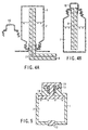
- FIG. 1 schematically shows the construction of a gist portion of a fuel cell using a liquid fuel tank of the present invention.
- the fuel cell shown in FIG. 1 is just an example of the fuel cell using a liquid fuel tank of the present invention.
- the arrangement of the components of the fuel cell and the sizes of these components are not limited to those shown in the drawing.
- the fuel cell shown in FIG. 1 consists essentially of a liquid fuel tank 1, a stacked body 2, and a pathway 3 for introducing a liquid fuel from the liquid fuel tank 1 into the stacked body 2.
- an air blowing-sucking mechanism (not shown) such as a fan is also arranged for supplying an oxidizing gas.
- the stacked body 2 shown in the drawing consists of a plurality of unit cells stacked one upon the other, each unit cell having an electromotive section including an electrolyte membrane sandwiched between a fuel electrode and an oxidant electrode. It is possible to use a unit cell in place of the stacked body consisting of a plurality of unit cells.
- FIG. 2 exemplifies the construction of the unit cell.
- the unit cell consists of a vaporizing plate a, an anode b, an electrolyte membrane c, a cathode d, and a gas channel e.
- a separator is interposed between two adjacent unit cells.
- the pathway 3 can be formed of such a fine tube as to perform a capillary function.
- the pathway 3 can be filled with a porous material through which permeates a liquid fuel in order to assist the liquid fuel introduction.
- a porous material such as carbon, a metal or a polyaniline, a porous material such as a vinyl polymer, an engineering plastic, or a thermosetting resin, ceramics porous body such as a silica porous body or an alumina porous body, a porous film such as a fluorocarbon polymer, polyethylene, polypropylene, polycarbonate, polyimide, polysulfone, polysulfide, or polybenzimidazol, a porous material of sponges such as polyurethane, polyester, cellulose, or phenol resin, and paper.
- a surface treatment so as to improve the wettability.
- the liquid fuel tank 1 is connected to the pathway 3 at a connection section 4. It is required that the connection section 4 is hermetically sealed. If the sealing property at the connecting section is not enough, the liquid fuel tends to be evaporated.
- the liquid fuel used in the present invention includes, for example, alcohols such as methanol, ethanol, or propanol, ethers such as diethyl ether, and hydrazine. Particularly, methanol is used in the form of a mixed solution together with water. Where the ratio of the contents is changed by evaporation, various problems come out. Naturally, it is desirable to prevent evaporation of the liquid fuel as much as possible.
- the connecting section 4 between the tank 1 and the pathway 3 should be hermetically sealed such that the alcohol evaporation can be prevented under atmospheric pressure.
- the connecting section 4 should be sealed such that the liquid fuel can be stored in the form of a liquid or a vapor at the saturated vapor pressure.
- liquid fuel holding material called a receiver 5.
- the liquid fuel is further introduced from the receiver 5 into each unit cell through a liquid fuel permeating material.
- the introduced liquid fuel is vaporized in a vaporizing section arranged in front of the fuel electrode within the unit cell and, then, further introduced into the fuel electrode.
- the liquid fuel is introduced Into the unit cell by a capillary force in the fuel cell of the present invention, it is not necessary to use a driving section for the fuel supply such as a pump. And as the liquid fuel introduced into the unit cell is vaporized within a fuel vaporizing layer by utilizing the reaction heat of the cell reaction, it is not necessary to use an auxiliary equipment such as a fuel evaporator. Also, since the gaseous fuel within the fuel vaporizing layer is kept substantially saturated, the liquid fuel is vaporized in the amount of the consumption of the gaseous fuel consumed by cell reaction in the vaporizing layer, and the liquid fuel is introduced into the unit cell by the capillary action to supply the vaporized portion alone.
- the fuel supply amount is interlocked with the amount of the fuel consumption, it is substantially impossible that the unreacted fuel is discharged to the outside of the fuel cell in the fuel cell of the present invention, making it unnecessary to set a processing system at the fuel outlet, like the conventional liquid fuel cell.
- the liquid fuel can be supplied smoothly in the fuel cell of the present invention without using auxiliary equipment such as a pump, a blower, a fuel evaporator, and condenser, making it possible to miniaturize the fuel cell.
- the liquid fuel tank 1 is equipped with a mechanism for adjusting the inner pressure in order to supply the liquid fuel with a high stability to the fuel vaporizing layer.
- a mechanism that permits the liquid fuel to flow out of the liquid fuel tank 1 in accordance with the consumed amount of the liquid fuel within the vaporizing layer For example, it is necessary to use a mechanism for taking a measure against a negative pressure, i.e., a mechanism for taking the air from outside the tank in accordance with the flow of the liquid fuel out of the fuel tank.
- a mechanism for taking a measure against a negative pressure i.e., a mechanism for taking the air from outside the tank in accordance with the flow of the liquid fuel out of the fuel tank.
- a fine hole 6 can be formed as a mechanism against the negative pressure on the side wall in the upper portion of the fuel tank 1 as shown in FIG. 1. It is possible to form a plurality of fine holes. Also, it is desirable for the diameter of the fine hole, which is not particularly limited in the present invention, to fall within a range of between about 0.2 mm and 5 mm, in view of the effect of preventing evaporation of an excessive amount of the liquid fuel.
- a removable film to the fine hole 6.
- a lid 9 can be mounted to the fine hole 6, as shown in FIG. 3.
- the fine hole 6 can be exposed to the outside by removing the film or the lid 9, as desired, so as to introduce the outer air into the fuel tank 1.
- a selectively permeable membrane can be mounted to the fine hole 6.
- a selectively permeable membrane required to have a low permeability of the vaporized material of the liquid fuel component and relatively high permeability of a gas such as the air.
- the selectively permeable membrane can be formed of, for example, a fluorocarbon-based FEP resin.
- the thickness of the selectively permeable membrane which is dependent on the kind and components of the liquid fuel used, and the saturated vapor pressure, etc., should be generally about 10 ⁇ m to 1000 ⁇ m.
- a mechanism against the negative pressure can be taken by positively introducing the gas component generated in the stacked body (fuel cell body) 2 into the liquid fuel tank 1.
- the present invention is not limited to the particular construction. Specifically, it is possible to combine the fuel permeating material 8 for transferring the liquid fuel and the gas introducing fine tube 11 for introducing gas generated in the stacked body 2 into the liquid fuel tank 1 by an optional method within the liquid fuel tank 1.
- FIG. 4A shows that the liquid fuel tank 1 is connected to the pathway 3. And the liquid fuel permeating material 8 and the gas introducing fine tube 11 extend to reach the stacked body 2 (not shown). Where the liquid fuel tank 1 is not connected to the pathway 3, the liquid fuel tank 1 is covered with a lid 10 so as to prevent a liquid fuel 7 housed in the tank 1 from being vaporized, as shown in FIG. 4B.
- the liquid fuel tends to be excessively supplied from the liquid fuel tank 1 into the stacked body 2 in accordance with the pressure increase. Further, the increase in the inner pressure of the liquid fuel tank 1 tends to cause rupture of the tank 1, which is dangerous.
- a pressure releasing mechanism for releasing the pressure when the inner pressure of the tank 1 has reached a predetermined high pressure. For example, it is considered effective to arrange a pressure release valve 15, which is operated by a spring 14 and an O-ring 13, in a part of the liquid fuel tank 1, as shown in FIG. 5. It is also effective for releasing the pressure to arrange a protective film that is ruptured under a pressure higher than a predetermined level.
- the pressure within the liquid fuel tank 1 can be adjusted by arranging the above-described mechanism for taking a measure against a negative pressure or mechanism for taking a measure against an excessively high pressure.
- the fuel should be supplied with a high stability regardless of the direction in which the fuel cell body (stacked body) is arranged.
- the fuel supply tends to be stopped, which makes the output fall down if the whole system has no device for supply of the fuel. Also, it causes the problem of the initial start-up characteristics.
- the liquid fuel it is desirable for the liquid fuel to flow smoothly from the liquid fuel tank connected to the stacked body 2 regardless of the direction in which the stacked body 2 is arranged.
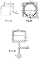
- the liquid fuel permeating material 8 is arranged within the liquid fuel tank 1 for expending to reach a fuel outlet port 12, as shown in FIGS. 6A and 6B.
- the liquid fuel permeating material 8 is arranged within the tank 1 on the inner surface where the liquid fuel outlet port 12 is formed and on the inner surface opposite to that where the liquid fuel outlet port 12 is formed.
- the liquid fuel permeating material 8 is arranged to cover the inner surface of the liquid fuel tank 1.
- liquid fuel permeating material 8 By arranging the liquid fuel permeating material 8 within the liquid fuel tank 1 in this fashion, the liquid fuel permeating material 8 is always partly kept in contact with the liquid fuel 7. It follows that the liquid fuel 7 can be supplied to the liquid fuel outlet port 12 regardless of the direction of the liquid fuel tank.
- the liquid fuel permeating material 8 is arranged in two mutually facing regions of the inner wall of the liquid fuel tank 1. As in the arrangement shown in FIG. 6A, the liquid fuel permeating material 8 is arranged to cover each of the mutually facing regions noted above. These two liquid fuel permeating materials 8 are in contact with the fine hole 6 formed on the outer wall of the fuel tank 1 for taking in the outer air and with the fuel outlet port 12. Since at least a part of the liquid fuel permeating material 8 is kept in contact with the liquid fuel, the liquid fuel can be supplied to the fuel outlet port 12 regardless of the direction of the tank 1 arrangement. Incidentally, where the liquid fuel tank 1 shown in FIG. 6B is turned upside down, the fine hole 6 for taking the outer air and the fuel outlet port 12 perform the opposite functions, i.e., the fine hole 6 acts as the fuel outlet port and the fuel outlet port 12 acts as the air-intake hole.
- FIGS. 7A and 7B show the particular construction. Specifically, in the liquid fuel tank shown in FIG. 7A, a fuel sealing part 30 is pushed by a spring 14, and the liquid fuel 7 is pushed out through the fuel outlet port 12. In the fuel tank shown in FIG. 7B, the liquid fuel 7 is housed in a bellows-shaped storage section 16 and pushed out through the fuel outlet port 12 by the function of the storage section itself.
- the sealed gas pressure in place of the mechanical pressure such as the spring force for pushing out the liquid fuel.
- the gas used as the sealing gas which is not particularly limited, it is desirable to use an inert gas such as an argon gas or a nitrogen gas.
- the pathway 3 for taking out the liquid fuel is formed of a flexible material and, thus, the liquid fuel tank 1 can be arranged such that the liquid fuel outlet port 12 is positioned in the lower portion regardless of the direction of the fuel cell body, i.e., stacked body, (not shown).
- the liquid fuel tank 1 shown in FIG. 8B is spherical and is supported within a support frame 17.
- a weight 19 is arranged in a predetermined position within the liquid fuel tank 1.
- a bearing 18 is arranged between the support frame 17 and the liquid fuel tank 1. The particular construction permits the storage section to be freely swung by 360° so as to make the fuel outlet port 12 positioned below the storage section regardless of the direction of fuel cell body, i.e., the stacked body, (not shown).
- the fuel outlet port 12 since the weight 19 is provided, the fuel outlet port 12 always positioned below the storage section. Further, the liquid fuel permeating material 8 is arranged within the liquid fuel tank 1 to reach the liquid fuel outlet port 12. It follows that the liquid fuel 7 can be supplied to the stacked body (not shown) as far as the liquid fuel is in contact with the liquid fuel permeating material 8.
- the other fuel permeating material is arranged between at least the liquid fuel tank and the liquid fuel permeating material of the cell body, i.e., the stacked body.
- the particular construction is employed in the present invention because, in the case of the fuel cell constructed such that the fuel permeating material is dipped directly in the liquid fuel in the liquid fuel tank, it was impossible to supply the liquid fuel with a high stability to the cell body (stacked body).
- the phenomenon described above occurs prominently. For example, where the fuel storage section was arranged on the upper side of the electrode, an excessively large amount of the fuel was supplied into the cell body. Further, the hermetic sealing properties at the fuel storage section and the cell body were not satisfactory, and the fuel is caused flow backward from the cell body into the liquid fuel tank.
- the fuel cell should not be constructed such that the fuel permeating material is inserted directly into the liquid fuel tank.
- the fuel cell is constructed such that the liquid fuel is once withdrawn from the liquid fuel tank by a permeating material differing from the liquid fuel permeating part and, then, the fuel is supplied from the permeating material into the liquid fuel permeating material 8. It is necessary to arrange at least one permeating material and it is possible to use second and third permeating materials. Where a plurality of permeating materials are used, the liquid fuel should be transferred smoothly from the liquid fuel tank to the fuel electrode. It follows that it is needed to use only the permeating material that is absolutely required.
- the number of permeating materials is increased, it is difficult to transfer the liquid fuel smoothly between the permeating materials themselves.
- the distance between the fuel and the fuel electrode is increased, it tends to take a long time for the initial rising of the fuel cell.
- the number of permeating materials and the positions of the permeating materials are determined by the positional relationship between the liquid fuel tank and the cell body. Naturally, it is desirable to arrange the permeating material in the shortest distance from the fuel outlet port of the liquid fuel tank and not to make the entire volume increased.
- the permeating material is required to exhibit the material characteristics adapted for the liquid fuel. What is particularly required is a satisfactory permeating rate.
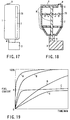
- the permeating rate is determined to be a rate of increase in the fuel content in the material at 25°C in the case where a permeating material having a size of 5 cm (width) ⁇ 10 cm (length) ⁇ 3 mm (thickness) is erected upright when dipped by 2 cm in a liquid fuel having a concentration of 10 mols/L (liter).
- FIG. 19 is a graph showing the change with time in the fuel content. The slope of each of the curves shown in the graph represents the rate of increase in the fuel content.
- the fuel content is determined as follows. First, the entire permeating material is dipped in the liquid fuel to permit the inner region of the permeating material to be saturated with the fuel and, then, the permeating material is withdrawn from the liquid fuel. In this case, the weight of the fuel contained in the permeating material is set at 100. The permeating rate is measured by the method described above, and the weight of the liquid fuel (%) at a certain time is determined as the fuel content at the particular time.
- an average sucking rate v(%/min) in the initial 5 minutes it is desirable for an average sucking rate v(%/min) in the initial 5 minutes to be as high as possible.
- the average sucking rate it is desirable for the average sucking rate to be 5 ⁇ v like curve B shown in FIG. 19. It is more desirable for the average sucking rate to be 6.5 ⁇ v like curve A shown in FIG. 19.
- the saturation point h of the fuel content it is desirable for the saturation point h of the fuel content to fall within a range of between 40 and 100, i.e., 40 ⁇ h ⁇ 100. If h is lower than 40, the fuel retention rate of the permeating material at the saturated point is low and, thus, particularly where the permeating material is high, it is impossible to supply the liquid fuel to the upper portion of the permeating material. Therefore, it is required that an absorbing material has a value of h falling within the range noted above.
- the wettability of the surface of the material with the liquid fuel In order to increase the sucking rate v, what is important is the wettability of the surface of the material with the liquid fuel. In the case of using a material with poor wettability, a surface treatment can be done on the material so as to improve the wettability.
- the material used in the present invention includes, for example, a porous body such as carbon, a metal or a polyaniline, a porous body such as a vinyl polymer, an engineering plastic material, or a thermosetting resin, a ceramic porous body such as a silica porous body or an alumina porous body, a porous film such as a fluorocarbon resin film, a polyethylene film, a polypropylene film, a polycarbonate film, a polyimide film, a polysulfone film, a polysulfide film or a polybenzimidazol film, a sponge-like porous material such as polyurethane, polyester, cellulose or a phenolic resin, and paper.
- a porous body such as carbon, a metal or a polyaniline
- a porous body such as a vinyl polymer, an engineering plastic material, or a thermosetting resin
- a ceramic porous body such as a silica porous body or an alumina porous
- a liquid fuel tank which can supply a liquid fuel with a high stability regardless of the direction of the fuel cell body (stacked body), is used in the present invention.
- the environment in which the fuel cell of the present invention is used is not limited, and the fuel cell of the present invention can be used in a wide field.
- the connecting section between the liquid fuel tank and the cell body (stacked body) is desirable for the connecting section between the liquid fuel tank and the cell body (stacked body) to be constructed such that the liquid fuel does not leak when transferred from the liquid fuel tank into the cell body so as to ensure a stable supply of the liquid fuel.
- the detachable liquid fuel tank should be desirably constructed such that the liquid fuel is not vaporized under the stored condition.
- FIGS. 9A and 9B show examples of the liquid fuel tank constructed in view of the requirement described above.
- FIG. 9A shows the state that the liquid fuel tank 1 is connected to the pathway 3.
- the liquid fuel permeating material 8 i.e., a material through which the liquid fuel easily permeates, is arranged within the liquid fuel tank 1 to reach the liquid fuel outlet port.
- the similar liquid fuel permeating material 8 is arranged within the pathway 3.
- the liquid fuel 7 is supplied through the liquid fuel permeating material 8 to the receiver 5 arranged with the fuel cell body (stacked body).
- the lid 10 Before the liquid fuel tank 1 of the particular construction is connected to the pathway 3, it is possible to mount the lid 10 as shown in FIG. 4B to cover the fuel outlet port so as to prevent the liquid fuel housed in the liquid fuel tank 1 from being vaporized. Alternatively, it is also possible to mount an opening-closing lid to the fuel outlet port so as to prevent the vaporization of the liquid fuel. Where the tank 1 is connected to the pathway as shown in FIG. 9A, the fuel permeating material 8 is exposed to the outside by detaching the lid of the tank 1 mounted to the fuel outlet port or by opening the lid mounted to the fuel outlet port so as to be connected to the pathway 3.
- FIG. 9B exemplifies the construction of the connecting section 4 shown in FIG. 9A.
- a cylindrical lid 31 which can be opened or closed, is slidably mounted around the fuel outlet port 12 of the liquid fuel tank 1, and a permeating material connecting pad 32 is mounted to the inner wall of the pathway 3.
- the outlet port opening-closing lid 31 is pushed upward so as to bring the outlet port 12 of the tank 1 into contact with the permeating material connection pad 32 of the pathway 3. If the fuel outlet port 12 is brought into contact with the permeating material connecting pad 32, the liquid fuel is transferred from the tank 1 into the pathway 3 by the capillary action.
- FIGS. 10A, 10B, 11A to 11C and 12 exemplify the connecting section between the liquid fuel tank and the pathway, covering the case where the liquid fuel tank is constructed as described above.
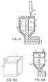
- FIG. 10A a slidable connecting section 33 and a tapered-angle central shaft 20 are arranged within the fuel outlet port of the liquid fuel tank 1.
- FIG. 10B is a plan view showing the flow out port.
- a projection 21 is formed on the inner wall of the pathway 3.
- the connecting section 33 is pushed upward by the projection 21. Since the tapered-angle central shaft 20 is upwardly tapered, the fine hole at the tip of the connecting section 33 is opened as the connecting section 33 is pushed upward, with the result that the liquid fuel 7 is allowed to flow from the liquid fuel tank 1 into the pathway 3.
- FIG. 10A The connecting section shown in FIG. 10A can be modified as shown in FIG. 11A.
- a boss 22 for pushing upward the connection section 33 of the fuel tank 1 when the fuel tank 1 is inserted into the pathway 3 is formed inside the pathway 3.
- FIGS. 11B and 11C are plan views showing the outlet section of the fuel tank 1 and the pathway 3, respectively. Since the tapered-angle central shaft 20 is tapered upward in the example shown in FIG. 11, too, the fine hole at the tip of the connecting section 33 is opened as the connecting section 33 is moved upward so as to permit the liquid fuel 7 to flow from the liquid fuel tank 1 into the pathway 3.
- a fuel outflow control valve 23 is mounted to the outflow section of the fuel tank 1 by a spring 14.
- a boss 22 for pushing the valve 23 upward when the fuel tank 1 is connected to the pathway 3 is mounted within the pathway 3. It follows that, when the liquid fuel tank 1 is connected to the pathway 3, the valve 23 mounted to the fuel tank 1 is pushed upward by the boss 22 so as to release the outflow hole and, thus, the liquid fuel 7 is supplied into the pathway 3.
- the O-ring 13 for hermetically sealing the liquid fuel which is shown in each of FIGS. 9A to 12, can be mounted on the side of the connecting section or on the side of the fuel cell body.
- the liquid fuel tank 1 is connected to the fuel cell body (stacked body) 2 such that the surface of the liquid fuel stored in the fuel tank 1 is perpendicular to the main surface of the electrolyte membrane included in the unit cell of the fuel cell body.
- the liquid fuel is supplied to the fuel cell body by utilizing the gravitational force, it is desirable for the liquid fuel tank 1 to be arranged on the upper portion of the fuel cell body (stacked body).
- the liquid fuel tank 1 is mounted to the upper portion of the fuel cell body as shown in the drawing, it is possible to connect the tank 1 to the fuel cell body 2 such that the liquid fuel can be introduced directly into the receiver 5.
- liquid fuel tank 1 it is also possible to connect the liquid fuel tank 1 directly to the side surface of the fuel cell body 2 as shown in FIGS. 14A and 14B. In this case, it is reasonable to state that the fuel cell body is connected to the liquid fuel tank 1 such that the surface of the liquid fuel stored in the liquid fuel tank 1 is parallel to the main surface of the electrolyte membrane included in the unit cell of the fuel cell body. It is also possible to mount the liquid fuel tank 1 in a lower portion of the fuel cell body, though the particular construction is not shown in the drawing. Where the liquid fuel tank 1 is arranged on the side surface or in a lower portion of the fuel cell body (stacked body), it is possible to supply the liquid fuel to the fuel cell body by utilizing, for example, the capillary force.
- the liquid fuel tank 1 In order to operate the fuel cell of the present invention for a long time, it is desirable for the liquid fuel tank 1 to be detachably connected to the fuel cell body 2. However, after the fuel tank 1 is connected to the fuel cell body 2, it is possible to fix the liquid fuel tank 1 to the pathway 3 or to the fuel cell body 2. Where the liquid fuel tank 1 is fixed to the pathway 3 or to the fuel cell body 2, it is desirable to form a fine hole 27 for replenishing the liquid fuel in a desired position, as shown in FIG. 15. In this case, the liquid fuel can be replenished through the fine hole 27 by using a liquid fuel replenishing tool 24 as shown in the drawing.
- the fuel cell of the present invention in spite of the small size, can be operated for a long time by replacing the liquid fuel tank 1 where the tank 1 is detachable or by replenishing the liquid fuel where the liquid fuel can be replenished.
- liquid fuel tank is detachable, it is desirable for the remaining amount of the liquid fuel within the fuel tank to be visually seen from the outside.
- the liquid fuel tank is constructed to be capable of replenishing the liquid fuel, it is desirable for the fuel tank to be constructed such that the remaining amount of the liquid fuel can be seen from the outside so as to make it possible to confirm the timing of replenishing the liquid fuel.
- a transparent or semi-transparent material for forming the liquid fuel tank 1 as shown in FIGS. 16A and 16B so as to make it possible to confirm the remaining amount of the liquid fuel from the outside.
- a transparent or semi-transparent material it is possible to use, for example, polyethylene, polypropylene, polycarbonate or a fluorine-containing resin such as polytetrafluoroethylene.
- the fuel can be colored with a substance that is not obstructive to the supply, vaporization and reaction of the liquid fuel. Inorganic or organic dyes, etc. can be considered as such a substance.
- a solid material having a specific gravity lower than that of the liquid fuel e.g., a polystyrene foam
- the remaining amount of the liquid fuel can be confirmed more easily by combining the floating material 26 with the liquid fuel tank 1 shown in FIG. 16 or 17.
- the material added to the liquid surface for detecting the surface of the liquid fuel is not limited to a solid material. It is also possible to use a liquid material such as a colored organic solvent or oil having a specific gravity lower than that of the liquid fuel.
- the liquid fuel can be supplied with a high stability even if the fuel cell body is arranged in an optional direction. In other words, the fuel supply with a high stability can be ensured regardless of the direction in which the fuel cell body (stacked body) is arranged. It follows that the scope of application of the fuel cell can be markedly widened.
- a unit cell included in the stacked body was manufactured as follows.
- a fuel electrode which has, a carbon cloth coated with a Pt-Ru catalyst layer with a size of 32 mm ⁇ 32 mm and an oxidant electrode which has a carbon cloth coated with a Pt black catalyst layer with a size of 32 mm ⁇ 32 mm.
- an electrolyte membrane consisting of a perfluorosulfonic acid membrane was held between the fuel electrode and the oxidant electrode such that the electrolyte membrane was in contact with the catalyst layers of the fuel electrode and the oxidant electrode.
- the resultant structure was bonded by hot pressing at 120°C for 5 minutes under a pressure of 100 kg/cm 2 so as to obtain an electromotive section.
- a unit cell having a reaction area of 10 cm 2 was prepared as follows; first, laminating the resultant electromotive section, a carbon porous plate used as a fuel vaporizing layer which has an average pore diameter of 85 ⁇ m and a porosity of 73%, and a carbon porous plate used as a fuel permeating layer which has an average pore diameter of 5 ⁇ m and a porosity of 40%, and then arranging the resultant laminate structure between an oxidant electrode holder equipped with an oxidant gas supply groove 2 mm deep and 1 mm wide and a fuel electrode holder. Ten unit cells thus prepared were stacked one upon the other so as to obtain a fuel cell body (stacked body).
- a mixed solution consisting of methanol and water mixed at a mixing ratio of 1:1 (molar ratio) was stored as a liquid fuel in the liquid fuel tank.
- a fine hole 6 having a diameter of about 5 mm was formed in the tank in the position shown in FIG. 1 and a selectively permeating film made of a fluorine-type FEP resin having a thickness of 25 ⁇ m was arranged as a mechanism for taking a mechanism against a negative pressure.
- the liquid fuel tank for a liquid fuel for the fuel cell was set in a connecting section of the liquid fuel cell body as shown in FIG. 1.
- a connecting section constructed as shown in FIG. 9 was used for the connection between the liquid fuel tank 1 and the pathway 3. Therefore, the liquid fuel 7 within the liquid fuel tank 1 was supplied by capillary action toward the fuel electrode through the pathway 3, the receiver 5, and the carbon porous plate.
- a fuel cell was prepared as in Example 1, except that used was a liquid fuel tank that did not include the fine hole as a mechanism against the negative pressure. Any of the construction of the fuel cell body, the connecting method between the fuel cell body and the liquid fuel tank, and fuel supply method and the fuel used was equal to that is Example 1.
- the fuel cell thus prepared was subjected to a power generation test at 80°C as in Example 1 by allowing the air of 1 atm. at 100 mL/min used as an oxidant gas to flow through a gas channel to reach the oxidizing electrode.
- the fuel cell for this Comparative Example 1 in which was used a liquid fuel tank not provided with a mechanism for taking a measure against a negative pressure, was found to be low in reliability.
- a fuel cell body was prepared as in Example 1, and a receiver section made of a material through which methanol permeates easily was arranged as the receiver 5.
- the material used herein exhibited a permeation rate denoted by curve A shown in the graph of FIG. 19.
- a liquid fuel tank that can be mounted directly on the upper portion of the fuel cell body 2 as shown in FIG. 13 was prepared, and two fine holes were formed as a measure against the negative pressure. These two fine holes were closed by caps. The two fine holes were formed diagonally apart from each other in the liquid fuel tank such that the outer air was taken into the liquid fuel tank through one of these two fine holes.
- a liquid fuel permeating material 8 as shown in FIG. 13 was arranged in the liquid fuel tank so as to make it possible to supply the liquid fuel regardless of the direction in which the fuel cell body was arranged.
- the liquid fuel tank of the particular construction was set in the fuel cell body 2. In this case, a connecting section constructed as shown in FIG. 9A was used for the connection between the liquid fuel tank 1 and the fuel cell body 2.
- the liquid fuel 7 housed in the liquid fuel tank 1 was supplied by the capillary action to the fuel electrode through the permeating material 8, the receiver 5 and the carbon porous plate.
- the cap 9 of the fine hole formed in an upper portion of the fuel tank 1 and used as a measure against the negative pressure was kept open.
- the fine hole 6 of the liquid fuel tank 1, said fine hole 6 providing a measure against the negative pressure was temporarily closed, and the liquid fuel tank was quietly turned upside down such that the fuel cell body 2 was positioned above the liquid fuel tank 1. Then, the other fine hole 6' providing a measure against the negative pressure was opened. Under this condition, the power generation was continued for 3 hours. However, a large change in the output was not recognized.
- the fuel cell of the present invention is capable of producing power regardless of the direction in which the fuel cell body is arranged.
- the liquid fuel i.e., a mixed solution of methanol and water, did not leak at all during operation of the fuel cell and did not leak when the liquid fuel tank was attached to and detached from the fuel cell body.
- a fuel cell was manufactured as in Example 2, except that a material poor in methanol permeability, i.e., a material having the permeating rate characteristics denoted by curve E shown in the graph of FIG. 19, was used for forming the receiver 5.
- a material poor in methanol permeability i.e., a material having the permeating rate characteristics denoted by curve E shown in the graph of FIG. 19, was used for forming the receiver 5.
- the air of 1 atm. at 100 mL/min used as an oxidizing agent was allowed to flow through the gas channel at 74°C so as to perform power generation as in Example 2.
- the fine hole 6 providing a measure against the negative pressure was temporarily closed during the power generating operation, and the liquid fuel tank was quietly turned upside down such that the fuel cell body 2 was positioned on the liquid fuel tank 1 as in Example 2. Then, the other fine hole 6' providing a measure against the negative pressure was released, and the power generation was continued. It has been found that the power output was rapidly lowered, and it took one hour for the power output to be stabilized again. And the power output stabilized was as low as that before turning the stack.
- a fuel cell body was prepared as in Example 1.
- liquid fuel tank for a fuel cell which was of the type that it was possible to replenish the liquid fuel as shown in FIG. 15.
- the liquid fuel tank was made of polycarbonate. Since the material used for forming the liquid fuel tank was semi-transparent, it was possible to visually confirm the remaining amount of the liquid fuel within the liquid fuel tank as already described in conjunction with FIGS. 16A and 16B.
- the liquid fuel was prepared by mixing methanol and water at 1:1 molar ratio and colored with an organic dye used. Further, some polystyrene foam balls each having a diameter of about 5 mm, which were described previously in conjunction with FIG. 18, were added to the liquid fuel.
- the liquid fuel thus prepared was loaded in an amount of 50 mL in the liquid fuel tank, and the tank was connected to the fuel cell body (stacked body). In this case, a connecting section constructed as shown in FIG. 9B was used for the connection between the liquid fuel tank 1 and the pathway 3. It follows that the liquid fuel 7 in the liquid fuel tank 1 was supplied by the capillary action to the fuel electrode through the permeating material 8, the receiver 5 and the carbon porous plate described previously.
- the cap 9 of the fine hole for supplying a liquid fuel and providing a measure against the negative pressure was detached. Under this condition, the air of 1 atm. at 80 mL/min used as an oxidant gas was supplied through the gas channel so as to start the power generation test of the fuel cell of the particular construction at 75°C.
- a fuel cell body was prepared as in Example 1.
- prepared was a liquid fuel tank for a fuel cell equipped with a mechanism providing a measure against the negative pressure as shown in FIG. 3. Then, 200 mL of a mixed solution of methanol and water mixed in the same molar ratio was stored as a liquid fuel in the liquid fuel tank.
- liquid fuel tank was connected to the fuel cell body so as to manufacture a fuel cell constructed as shown in FIG. 1.
- the fine tube 11 capable of introducing the gas generated on the side of the fuel cell body was arranged within the liquid fuel tank 1 and within the liquid absorbing material 8.
- One end of the fine tube 11 was open within the liquid fuel tank and the other end is open to provide a space for collecting the carbon dioxide gas generated on the side of the anode of the fuel cell body 2.
- a pressure control valve was mounted to the fine tube 11 so as to make it possible to release the pressure through the valve over a predetermined level of pressure.
- the pressure within the fuel cell body was temporarily elevated because of the carbon dioxide gas generation.
- the inner pressure not elevated further because the pressure release valve mounted to the fine tube was opened.
- a problem such as leakage of the liquid fuel was not generated at all, supporting that the fuel cell was operated as a fuel cell having a high reliability.
- a fuel cell body was prepared as in Example 1.
- a liquid fuel tank 1 having a rotatable storage section as shown in FIG. 8B.
- a fine hole having a diameter of about 3 mm was formed on the wall of the tank in the liquid fuel tank, and a selectively permeable Teflon series FEP membrane having a thickness of 30 ⁇ m was arranged as a measure against the negative pressure.
- a liquid fuel consisting of a mixed solution of methanol and water mixed in the same molar ratio was stored in an amount of 150 mL in the liquid fuel tank, and the liquid fuel tank was connected to the fuel cell body with a flexible pathway so as to obtain a fuel cell.
- a liquid fuel permeating material was arranged within the pathway.
- the liquid fuel was supplied by the capillary action to the anode side of the fuel cell constructed as described above, and the air of 1 atm. at 90 mL/min used as an oxidant gas was supplied to the cathode side through a gas channel so as to start a power generation test at 80°C.
- the output power having a voltage of 4.8V and a current density of 300 mA/cm 2 .
- the power output was found to be stable after the power generation for about 6 hours.
- the fuel cell body (stacked body) was inclined by about 15° during the power generating operation.
- the liquid fuel could be supplied to the fuel cell body smoothly, making it possible to continue a stable power generation.
- the present invention provides a highly reliable fuel cell, which permits simplifying the liquid fuel supply system, which permits stably supplying a liquid fuel, and which permits producing a stable output.
- the present invention also provides a liquid fuel tank for a fuel cell, which permits vaporizing a liquid fuel and supplying a vaporized fuel with a simple structure without using a pump or a blower, making it possible for the fuel cell to produce a high output with a high stability. Also, since the liquid fuel tank is provided with a pressure adjusting mechanism, it is possible to supply a liquid fuel to the fuel vaporizing section with a high stability. As a result, it is possible to obtain a highly reliable fuel cell low in change of the output power even if the power generation is carried out continuously.
- the liquid fuel can be supplied continuously from the liquid fuel tank regardless of the direction in which the fuel cell body is arranged, making it possible to use and set the fuel cell at any place and in any direction.
- the flow of the liquid fuel from the liquid fuel tank is automatically started and stopped by the attachment and detachment of the liquid fuel tank respectively, the flow of the liquid fuel can be controlled easily. It is also possible to suppress an undesired outflow and vaporization of the fuel.
- the present invention makes it possible to satisfy simultaneously the requirements of a high performance and simplification of the system for the first time.
- the present invention has made it possible to miniaturize the fuel cell, to supply the liquid fuel with a high stability during operation of the fuel cell, and to prevent the fuel leakage, leading to manufacture of a highly reliable fuel cell.
- the present invention is of a very high industrial value.
Landscapes
- Life Sciences & Earth Sciences (AREA)
- Engineering & Computer Science (AREA)
- Manufacturing & Machinery (AREA)
- Sustainable Development (AREA)
- Sustainable Energy (AREA)
- Chemical & Material Sciences (AREA)
- Chemical Kinetics & Catalysis (AREA)
- Electrochemistry (AREA)
- General Chemical & Material Sciences (AREA)
- Fuel Cell (AREA)
Applications Claiming Priority (2)
| Application Number | Priority Date | Filing Date | Title |
|---|---|---|---|
| JP26721199A JP3668069B2 (ja) | 1999-09-21 | 1999-09-21 | 燃料電池用液体燃料収容容器および燃料電池 |
| JP26721199 | 1999-09-21 |
Publications (2)
| Publication Number | Publication Date |
|---|---|
| EP1087455A2 true EP1087455A2 (fr) | 2001-03-28 |
| EP1087455A3 EP1087455A3 (fr) | 2004-03-03 |
Family
ID=17441691
Family Applications (1)
| Application Number | Title | Priority Date | Filing Date |
|---|---|---|---|
| EP00307819A Withdrawn EP1087455A3 (fr) | 1999-09-21 | 2000-09-11 | Réservoir contenant du combustible liquide pour pile à combustible et pile à combustible |
Country Status (3)
| Country | Link |
|---|---|
| US (2) | US6506513B1 (fr) |
| EP (1) | EP1087455A3 (fr) |
| JP (1) | JP3668069B2 (fr) |
Cited By (39)
| Publication number | Priority date | Publication date | Assignee | Title |
|---|---|---|---|---|
| WO2001054216A3 (fr) * | 2000-01-18 | 2002-02-21 | Univ Ramot | Pile a combustible a membrane conductrice de protons |
| US6447943B1 (en) | 2000-01-18 | 2002-09-10 | Ramot University Authority For Applied Research & Industrial Development Ltd. | Fuel cell with proton conducting membrane with a pore size less than 30 nm |
| EP1280219A3 (fr) * | 2001-06-28 | 2003-08-27 | Foamex L.P. | Réservoir de combustible liquide pour pile à combustible |
| WO2002099916A3 (fr) * | 2001-06-01 | 2003-09-25 | Polyfuel Inc | Ensemble pile a combustible destine a un dispositif electronique portable et circuit d'interface, de commande et de regulation pour dispositif electronique alimente par pile a combustible |
| WO2003040618A3 (fr) * | 2001-11-07 | 2003-12-11 | Battelle Memorial Institute | Micro-chambres de combustion, micro-reformateurs et procedes de combustion et de reformage de fluides |
| WO2003096463A3 (fr) * | 2002-05-09 | 2005-01-13 | Hewlett Packard Development Co | Systeme d'alimentation en combustible et son mode d'utilisation |
| WO2004049486A3 (fr) * | 2002-11-27 | 2005-01-27 | Hydrogenics Corp | Alimentation en reactif pour systeme electrique a pile a combustible |
| WO2005013406A1 (fr) | 2003-07-29 | 2005-02-10 | Societe Bic | Cartouche de combustible a contenant flexible |
| WO2003012906A3 (fr) * | 2001-07-27 | 2005-02-10 | Siemens Ag | Pile a combustible methanol directe portable |
| EP1513213A1 (fr) * | 2003-09-05 | 2005-03-09 | Samsung Electronics Co., Ltd. | Dispositif d'alimentation en combustible pour pile à combustible directe au méthanol |
| WO2005031903A3 (fr) * | 2003-09-25 | 2005-05-26 | Casio Computer Co Ltd | Dispositif de production d'energie, contenant de combustible et dispositif servant a mesurer la quantite de combustible restant |
| WO2004093229A3 (fr) * | 2003-04-15 | 2005-08-11 | Gillette Co | Appareil destine a realimenter en combustible une pile a combustible a oxydation directe |
| EP1564476A1 (fr) * | 2004-07-12 | 2005-08-17 | SFC Smart Fuel Cell AG | Cartouche de carburant externe avec interface de sécurité |
| EP1328033A3 (fr) * | 2002-01-11 | 2005-08-31 | Hewlett-Packard Company | Système indicateur de concentration de carburant à base de colorants pour systèmes de piles à combustible |
| EP1331684A3 (fr) * | 2002-01-22 | 2005-09-14 | Hewlett-Packard Company | Alimentation en combustible d'une pile à combustible |
| WO2005117183A1 (fr) | 2004-05-27 | 2005-12-08 | Mitsubishi Pencil Co., Ltd. | Reservoir a combustible pour pile a combustible |
| WO2004093232A3 (fr) * | 2003-04-15 | 2005-12-15 | Mti Microfuel Cells Inc | Dispositif de pile a combustible a amenee de vapeur comprenant une alimentation en combustible reglable |
| WO2006001418A1 (fr) | 2004-06-25 | 2006-01-05 | Mitsubishi Pencil Co., Ltd. | Corps d’emmagasinage de combustible de pile à combustible |
| US6994932B2 (en) | 2001-06-28 | 2006-02-07 | Foamex L.P. | Liquid fuel reservoir for fuel cells |
| WO2005004272A3 (fr) * | 2003-06-27 | 2006-02-09 | Gillette Co | Procedes pour assurer la realimentation en combustible de dispositifs alimentes par une pile a combustible |
| WO2006010012A3 (fr) * | 2004-07-08 | 2006-07-06 | Direct Methanol Fuel Cell Corp | Cartouche de pile a combustible et systeme de distribution de combustible |
| WO2006085428A1 (fr) * | 2005-02-10 | 2006-08-17 | Sony Corporation | Générateur d’énergie électrochimique et son procédé d’entraînement |
| EP1293007A4 (fr) * | 2000-06-13 | 2006-12-20 | California Inst Of Techn | Pile a combustible de taille reduite pour applications portables |
| WO2007119543A1 (fr) * | 2006-03-20 | 2007-10-25 | Casio Computer Co., Ltd. | Cartouche de liquide |
| US7291410B2 (en) | 2002-09-18 | 2007-11-06 | Kinkelaar Mark R | Orientation independent liquid fuel reservoir |
| US7316855B2 (en) | 2001-06-01 | 2008-01-08 | Polyfuel, Inc. | Fuel cell assembly for portable electronic device and interface, control, and regulator circuit for fuel cell powered electronic device |
| EP1464091A4 (fr) * | 2002-01-08 | 2008-03-19 | Gillette Co | Reservoir et distributeur a combustible pour dispositif de pile a combustible a alimentation liquide |
| EP1758190A4 (fr) * | 2004-06-08 | 2008-07-16 | Mitsubishi Pencil Co | Corps de stockage de combustible pour cellule électrochimique |
| EP1770809A4 (fr) * | 2004-06-25 | 2008-07-23 | Mitsubishi Pencil Co | Pile à combustible |
| EP1476238A4 (fr) * | 2002-02-19 | 2008-08-27 | Mti Microfuel Cells Inc | Systeme de pile a combustible a oxydation directe simplifiee |
| DE10319885B4 (de) * | 2003-04-25 | 2008-10-16 | Gkss-Forschungszentrum Geesthacht Gmbh | Sicherungsvorrichtung |
| EP1593170A4 (fr) * | 2003-01-15 | 2009-01-21 | Sendyne Corp | Procede d'alimentation pour pile a combustible a methanol direct |
| EP1717893A4 (fr) * | 2004-02-02 | 2009-05-13 | Mitsubishi Pencil Co | Batterie combustible et stockage du combustible pour une batterie combustible |
| EP1751816A4 (fr) * | 2004-05-26 | 2009-08-12 | Bic Soc | Appareil et procede de production in situ de combustible pour pile a combustible |
| US7585472B2 (en) | 2001-11-07 | 2009-09-08 | Battelle Memorial Institute | Microcombustors, microreformers, and methods involving combusting or reforming fluids |
| US7625655B1 (en) | 2002-01-08 | 2009-12-01 | The Gillette Company | Fuel container and delivery apparatus for a liquid feed fuel cell system |
| US7678485B2 (en) | 2003-12-09 | 2010-03-16 | Nec Corporation | Fuel cartridge, fuel cell and portable electrical appliance including fuel cell |
| EP2259372A3 (fr) * | 2003-01-31 | 2011-03-09 | Société BIC | Cartouche de combustible pour piles a combustible |
| EP2456001A1 (fr) * | 2005-10-05 | 2012-05-23 | Société BIC | Cartouche à combustible pour piles à combustible |
Families Citing this family (139)
| Publication number | Priority date | Publication date | Assignee | Title |
|---|---|---|---|---|
| US6632553B2 (en) * | 2001-03-27 | 2003-10-14 | Mti Microfuel Cells, Inc. | Methods and apparatuses for managing effluent products in a fuel cell system |
| US6686081B2 (en) * | 2001-05-15 | 2004-02-03 | Mti Microfuel Cells, Inc. | Methods and apparatuses for a pressure driven fuel cell system |
| EP1258937A1 (fr) * | 2001-05-17 | 2002-11-20 | STMicroelectronics S.r.l. | Micropile à combustible à silicium, méthode de fabrication et dispositif semiconducteur autonome comportant une micropile à combustible |
| JP4599772B2 (ja) * | 2001-07-19 | 2010-12-15 | カシオ計算機株式会社 | 電源システム |
| JP4094265B2 (ja) * | 2001-09-25 | 2008-06-04 | 株式会社日立製作所 | 燃料電池発電装置とそれを用いた装置 |
| KR100663170B1 (ko) * | 2001-12-07 | 2007-01-02 | 캐논 가부시끼가이샤 | 연료전지 및 전기기기 |
| US6789421B2 (en) * | 2002-01-11 | 2004-09-14 | Hewlett-Packard Development Company, L.P. | Density-based fuel indicator system for fuel cells |
| US20030138679A1 (en) * | 2002-01-22 | 2003-07-24 | Ravi Prased | Fuel cartridge and reaction chamber |
| US6924055B2 (en) * | 2002-02-27 | 2005-08-02 | The Gillette Company | Fuel delivery cartridge and anodic fuel receptor for a fuel cell |
| JP4155021B2 (ja) | 2002-02-28 | 2008-09-24 | カシオ計算機株式会社 | 発電型電源及び電子機器 |
| JP4858180B2 (ja) * | 2002-02-28 | 2012-01-18 | カシオ計算機株式会社 | 発電型電源及び電子機器 |
| KR100493153B1 (ko) * | 2002-03-20 | 2005-06-03 | 삼성에스디아이 주식회사 | 공기 호흡형 직접 메탄올 연료전지 셀팩 |
| JP3696171B2 (ja) * | 2002-04-16 | 2005-09-14 | 株式会社東芝 | 直接型液体燃料電池発電装置の検査方法、検査装置、及び直接型液体燃料電池発電装置 |
| KR100450820B1 (ko) | 2002-04-23 | 2004-10-01 | 삼성에스디아이 주식회사 | 공기 호흡형 직접 메탄올 연료전지 셀팩 |
| US6926989B2 (en) * | 2002-06-05 | 2005-08-09 | Motorola, Inc. | Interconnect apparatus for fuel cells |
| JP3748434B2 (ja) * | 2002-06-12 | 2006-02-22 | 株式会社東芝 | 直接型メタノール燃料電池システム及び燃料カートリッジ |
| US7097813B2 (en) * | 2002-06-21 | 2006-08-29 | Hewlett-Packard Development Company, L.P. | Hydrogen generating apparatus |
| JP2005531901A (ja) * | 2002-06-28 | 2005-10-20 | フォーメックス エル ピー | 液体燃料電池用の燃料貯槽 |
| JP3838947B2 (ja) | 2002-07-26 | 2006-10-25 | 三菱鉛筆株式会社 | 直接メタノール型燃料電池 |
| JP2004134355A (ja) * | 2002-08-16 | 2004-04-30 | Fuji Photo Film Co Ltd | 燃料電池、電子機器、携帯端末及びカメラ |
| JP4724998B2 (ja) * | 2002-08-29 | 2011-07-13 | カシオ計算機株式会社 | 発電用燃料容器及び携帯機器 |
| JP4831925B2 (ja) * | 2002-09-26 | 2011-12-07 | トヨタ自動車株式会社 | 燃料電池システムの燃料残量に関する警告 |
| US7282283B2 (en) * | 2002-09-28 | 2007-10-16 | Motorola, Inc. | Method and device for limiting crossover in fuel cell systems |
| JP3821081B2 (ja) * | 2002-09-30 | 2006-09-13 | 日本電気株式会社 | 燃料電池およびこれを搭載した携帯機器ならびに燃料電池の運転方法 |
| JP3742385B2 (ja) | 2002-12-26 | 2006-02-01 | 株式会社東芝 | 直接型メタノール燃料電池システム、携帯用電子機器及び直接型メタノール燃料電池システムの液体燃料残存量の検出方法 |
| US20040126643A1 (en) * | 2002-12-27 | 2004-07-01 | Kinkelaar Mark R. | Orientation independent fuel reservoir containing liquid fuel |
| JP4508539B2 (ja) * | 2003-02-13 | 2010-07-21 | 日本電気株式会社 | 燃料供給カートリッジ、燃料電池装置、および燃料供給方法 |
| TWI239113B (en) * | 2003-03-13 | 2005-09-01 | Ind Tech Res Inst | Fuel supply body and method for maintaining fuel concentration of fuel cell |
| JP4670223B2 (ja) * | 2003-03-19 | 2011-04-13 | カシオ計算機株式会社 | 燃料容器 |
| TWI241049B (en) | 2003-03-19 | 2005-10-01 | Casio Computer Co Ltd | Fuel container |
| US20040247960A1 (en) * | 2003-03-31 | 2004-12-09 | Kabushiki Kaisha Toshiba | Fuel cell system |
| US7282293B2 (en) * | 2003-04-15 | 2007-10-16 | Mti Microfuel Cells Inc. | Passive water management techniques in direct methanol fuel cells |
| US7407721B2 (en) * | 2003-04-15 | 2008-08-05 | Mti Microfuel Cells, Inc. | Direct oxidation fuel cell operating with direct feed of concentrated fuel under passive water management |
| US20050170224A1 (en) * | 2003-04-15 | 2005-08-04 | Xiaoming Ren | Controlled direct liquid injection vapor feed for a DMFC |
| US6936368B2 (en) * | 2003-04-16 | 2005-08-30 | The Gillette Company | System and method for safe removal/oxidative decomposition of fuel from a fuel container |
| JP2004326386A (ja) * | 2003-04-24 | 2004-11-18 | Mitsubishi Electric Corp | 評価支援装置及び評価支援方法及び評価支援プログラム |
| CN100424922C (zh) * | 2003-05-16 | 2008-10-08 | 株式会社杰士汤浅 | 液体燃料型燃料电池及其燃料 |
| US20070042234A1 (en) * | 2003-05-16 | 2007-02-22 | Gs Yuasa Corporation | Liquid fuel type fuel cell and fuel therefor |
| US20050019641A1 (en) * | 2003-06-18 | 2005-01-27 | Toshiyuki Aoyama | Fuel tank for fuel-cell and fuel cell system |
| WO2005004258A2 (fr) * | 2003-06-27 | 2005-01-13 | Ultracell Corporation | Cartouche portable de combustible pour pile a combustible |
| US20060127711A1 (en) * | 2004-06-25 | 2006-06-15 | Ultracell Corporation, A California Corporation | Systems and methods for fuel cartridge distribution |
| JP4438983B2 (ja) * | 2003-07-03 | 2010-03-24 | 株式会社東海 | 燃料電池用燃料容器 |
| JPWO2005008817A1 (ja) * | 2003-07-18 | 2006-09-07 | 株式会社ジーエス・ユアサコーポレーション | 燃料電池システムと燃料電池の燃料切れの検出方法 |
| US7617842B2 (en) | 2003-07-29 | 2009-11-17 | SOCIéTé BIC | Valves for fuel cartridges |
| US7537024B2 (en) * | 2003-07-29 | 2009-05-26 | Societe Bic | Fuel cartridge with connecting valve |
| WO2005020358A1 (fr) * | 2003-08-22 | 2005-03-03 | Nec Corporation | Unite d'alimentation en combustible pour pile a combustible et pile a combustible utilisant une telle unite |
| JP3989471B2 (ja) | 2003-09-12 | 2007-10-10 | 三洋電機株式会社 | 燃料電池装置 |
| US8084166B2 (en) * | 2003-09-16 | 2011-12-27 | The Gillette Company | Enhanced fuel delivery for direct methanol fuel cells |
| US8114554B2 (en) * | 2003-09-16 | 2012-02-14 | The Gillette Company—South Boston | Enhanced fuel delivery for direct methanol fuel cells |
| US20050057555A1 (en) * | 2003-09-17 | 2005-03-17 | Hitachi Maxell, Ltd. | Information processing apparatus |
| JP4449385B2 (ja) * | 2003-09-25 | 2010-04-14 | カシオ計算機株式会社 | 発電装置及び燃料貯留モジュール |
| JP2005108559A (ja) * | 2003-09-29 | 2005-04-21 | Casio Comput Co Ltd | 燃料容器 |
| US7674540B2 (en) * | 2003-10-06 | 2010-03-09 | Societe Bic | Fuel cartridges for fuel cells and methods for making same |
| US7255947B2 (en) * | 2003-10-17 | 2007-08-14 | The Gillette Company | Fuel substance and associated cartridge for fuel cell |
| US7115335B2 (en) * | 2003-10-31 | 2006-10-03 | Entegris, Inc. | Connector assembly for fluid transfer |
| JP2005158335A (ja) * | 2003-11-21 | 2005-06-16 | Denso Corp | 燃料電池システム |
| US7059582B2 (en) * | 2003-12-01 | 2006-06-13 | Societe Bic | Fuel cell supply having fuel compatible materials |
| US7306869B2 (en) * | 2003-12-02 | 2007-12-11 | Mti Microfuel Cells Inc. | Electrostatically actuated shutter and array for use in a direct oxidation fuel cell |
| US20050164055A1 (en) * | 2003-12-17 | 2005-07-28 | Kenji Hasegawa | Fuel cell system and power generating method in fuel cell system |
| JP3889002B2 (ja) * | 2004-01-07 | 2007-03-07 | 松下電器産業株式会社 | 燃料電池 |
| JP4944444B2 (ja) * | 2004-01-20 | 2012-05-30 | 株式会社日立製作所 | 燃料電池用燃料容器 |
| JP4733351B2 (ja) * | 2004-01-20 | 2011-07-27 | 株式会社東海 | 燃料電池用燃料容器 |
| CN1910777B (zh) * | 2004-01-20 | 2010-05-05 | 株式会社日立制作所 | 燃料电池用燃料容器 |
| US20070154768A1 (en) * | 2004-01-22 | 2007-07-05 | Yoshinori Watanabe | Fuel cartridge for fuel cell and fuel cell using the same |
| CN100499233C (zh) * | 2004-01-23 | 2009-06-10 | 日本电气株式会社 | 用于燃料电池的燃料盒以及使用该燃料盒的燃料电池 |
| US20100000434A1 (en) * | 2004-01-23 | 2010-01-07 | Pristash David J | Micro fuel cell with membrane storage |
| JP4716660B2 (ja) * | 2004-02-02 | 2011-07-06 | 三菱鉛筆株式会社 | 直接メタノール型燃料電池 |
| JP4716658B2 (ja) * | 2004-02-02 | 2011-07-06 | 三菱鉛筆株式会社 | 直接メタノール型燃料電池 |
| JP4716659B2 (ja) * | 2004-02-02 | 2011-07-06 | 三菱鉛筆株式会社 | 直接メタノール型燃料電池 |
| JP4634728B2 (ja) * | 2004-02-16 | 2011-02-16 | 株式会社東海 | 燃料電池用燃料容器 |
| CN1922751A (zh) * | 2004-02-25 | 2007-02-28 | 松下电器产业株式会社 | 燃料电池用燃料箱以及燃料电池系统 |
| JP4796750B2 (ja) * | 2004-04-27 | 2011-10-19 | 三菱鉛筆株式会社 | 燃料電池 |
| JP2005327538A (ja) * | 2004-05-13 | 2005-11-24 | Mitsubishi Pencil Co Ltd | 液体燃料貯蔵容器 |
| JP5008252B2 (ja) * | 2004-05-18 | 2012-08-22 | パナソニック株式会社 | 燃料電池用液体燃料収納容器及び燃料電池システム |
| CN1321476C (zh) * | 2004-05-24 | 2007-06-13 | 胜光科技股份有限公司 | 燃料电池的进料控制结构 |
| JP4768236B2 (ja) * | 2004-06-15 | 2011-09-07 | 株式会社日立製作所 | 燃料電池、その燃料供給システム、燃料カートリッジ並びに電子機器 |
| US7648792B2 (en) * | 2004-06-25 | 2010-01-19 | Ultracell Corporation | Disposable component on a fuel cartridge and for use with a portable fuel cell system |
| US7968250B2 (en) * | 2004-06-25 | 2011-06-28 | Ultracell Corporation | Fuel cartridge connectivity |
| JP2006024401A (ja) * | 2004-07-07 | 2006-01-26 | Hitachi Ltd | 燃料電池 |
| JP2006054055A (ja) * | 2004-07-16 | 2006-02-23 | Tokai Corp | 燃料電池用燃料カートリッジの接続構造 |
| JP5152618B2 (ja) * | 2004-07-27 | 2013-02-27 | フマキラー株式会社 | 燃料電池を電源とする送風式薬剤拡散装置 |
| WO2006013752A1 (fr) * | 2004-08-02 | 2006-02-09 | Matsushita Electric Industrial Co., Ltd. | Mécanisme d’alimentation en combustible pour réservoir à combustible |
| JP5099963B2 (ja) * | 2004-08-02 | 2012-12-19 | 三菱鉛筆株式会社 | 燃料電池における液体燃料供給システム |
| JP4568053B2 (ja) * | 2004-08-10 | 2010-10-27 | 富士通株式会社 | 燃料電池 |
| JP2006079955A (ja) | 2004-09-10 | 2006-03-23 | Casio Comput Co Ltd | 燃料電池システム及び発電用燃料容器 |
| KR100624919B1 (ko) * | 2004-09-22 | 2006-09-15 | 삼성에스디아이 주식회사 | 이차 전지 |
| JP2006108028A (ja) * | 2004-10-08 | 2006-04-20 | Toshiba Corp | 燃料電池 |
| JP4738790B2 (ja) | 2004-10-27 | 2011-08-03 | キヤノン株式会社 | 直接メタノール型燃料電池用液体燃料、カートリッジおよび燃料電池システム |
| JP4781657B2 (ja) * | 2004-10-29 | 2011-09-28 | 三菱鉛筆株式会社 | 燃料カートリッジ |
| US7687178B2 (en) | 2004-11-01 | 2010-03-30 | Casio Computer Co., Ltd. | Fuel container |
| RU2344518C1 (ru) * | 2004-11-05 | 2009-01-20 | Юоп Ллк | Твердое топливо для топливных элементов |
| KR100612912B1 (ko) | 2004-12-15 | 2006-08-14 | 삼성에스디아이 주식회사 | 직접액체연료전지용 연료공급장치 |
| JP4822497B2 (ja) * | 2004-12-17 | 2011-11-24 | Necエンベデッドプロダクツ株式会社 | 燃料電池カートリッジおよび、これを着脱自在な情報処理装置 |
| US8820569B2 (en) | 2004-12-17 | 2014-09-02 | Casio Computer Co., Ltd. | Fuel container, fuel residual amount measurement device, and fuel residual amount measurement method |
| JP2006209679A (ja) * | 2005-01-31 | 2006-08-10 | Fuji Photo Film Co Ltd | 記憶媒体及び電子機器並びに情報読出装置 |
| JP2006221828A (ja) * | 2005-02-08 | 2006-08-24 | Sony Corp | 燃料電池システム |
| EP2447162A1 (fr) | 2005-02-16 | 2012-05-02 | Société BIC | Systèmes d'alimentation en carburant dotés d'une résistance opérationnelle |
| JP4741854B2 (ja) * | 2005-02-17 | 2011-08-10 | カシオ計算機株式会社 | 燃料容器 |
| JP4871515B2 (ja) * | 2005-02-17 | 2012-02-08 | キヤノン株式会社 | 電子機器 |
| JP4599204B2 (ja) * | 2005-03-29 | 2010-12-15 | 株式会社東芝 | 燃料容器および燃料供給システム |
| ITVA20050034A1 (it) * | 2005-05-13 | 2006-11-14 | St Microelectronics Srl | Celle a combustibile realizzate in un singolo strato di silicio monocristallino e processo di fabbricazione |
| KR100657960B1 (ko) | 2005-05-17 | 2006-12-14 | 삼성에스디아이 주식회사 | 연료 전지 시스템 및 이를 구비하는 모바일 통신기기 |
| EP1906479A4 (fr) * | 2005-07-15 | 2009-12-09 | Toshiba Kk | Batterie de piles à combustible |
| KR100707161B1 (ko) | 2005-07-16 | 2007-04-13 | 삼성에스디아이 주식회사 | 연료 카트리지 및 이를 구비한 직접액체 연료전지 |
| JP2007095438A (ja) * | 2005-09-28 | 2007-04-12 | Hitachi Ltd | 燃料電池 |
| JP2007095400A (ja) * | 2005-09-28 | 2007-04-12 | Hitachi Ltd | 燃料カートリッジ |
| US7779856B2 (en) * | 2005-10-05 | 2010-08-24 | Societe Bic | Fuel cartridge of a fuel cell with fuel stored outside fuel liner |
| EP1798799B1 (fr) * | 2005-12-16 | 2008-09-24 | STMicroelectronics S.r.l. | Pile à combustible planairement intégrée sur un circuit intégré de silicium monocristallin et procédé de fabrication |
| US20070151983A1 (en) * | 2005-12-30 | 2007-07-05 | Nimesh Patel | Fuel cartridge with a flexible bladder for storing and delivering a vaporizable liquid fuel stream to a fuel cell system |
| US8196894B2 (en) * | 2006-01-06 | 2012-06-12 | Societe Bic | Check valves for fuel cartridges |
| US20080029156A1 (en) * | 2006-01-19 | 2008-02-07 | Rosal Manuel A D | Fuel cartridge |
| US20080131740A1 (en) * | 2006-01-19 | 2008-06-05 | Manuel Arranz Del Rosal | Fuel cartridge coupling valve |
| JP4880318B2 (ja) * | 2006-02-10 | 2012-02-22 | 株式会社東海 | 燃料カートリッジ |
| KR101252839B1 (ko) * | 2006-03-03 | 2013-04-09 | 삼성에스디아이 주식회사 | 회수장치를 채용한 연료전지 |
| JP2007257858A (ja) * | 2006-03-20 | 2007-10-04 | Toshiba Corp | 燃料電池 |
| JP4846403B2 (ja) | 2006-03-22 | 2011-12-28 | カシオ計算機株式会社 | 燃料容器 |
| DE112007000759T5 (de) | 2006-03-27 | 2009-01-29 | Mitsubishi Pencil Co. Limited | Brennstoffzelle |
| JP5063935B2 (ja) * | 2006-06-02 | 2012-10-31 | 東洋製罐株式会社 | 燃料電池カートリッジ用ポリエステル製容器 |
| DE102006030236A1 (de) * | 2006-06-30 | 2008-01-03 | Fraunhofer-Gesellschaft zur Förderung der angewandten Forschung e.V. | Direktoxidationsbrennstoffzelle für den konvektionsfreien Transport des Brennstoffs und Verfahren zum Betreiben der Brennstoffzelle |
| JP4827635B2 (ja) * | 2006-07-07 | 2011-11-30 | 三菱鉛筆株式会社 | 直接メタノール型燃料電池 |
| US8235077B2 (en) * | 2006-09-14 | 2012-08-07 | Societe Bic | Device for refilling a fuel cartridge for a fuel cell |
| WO2008035423A1 (fr) * | 2006-09-21 | 2008-03-27 | Fujitsu Limited | Cellule à combustible |
| DE102006049031B4 (de) * | 2006-10-13 | 2009-10-22 | Futuree Fuel Cell Solutions Gmbh | Tragbehälter einer Energieversorgungseinheit mit Brennstoffzellen, dessen Verwendung und Verfahren zur Gefährdungsreduzierung |
| JP2007123293A (ja) * | 2007-02-15 | 2007-05-17 | Seiko Epson Corp | 燃料カートリッジ |
| JP2008218012A (ja) * | 2007-02-28 | 2008-09-18 | Toshiba Corp | 燃料電池 |
| JP4768698B2 (ja) * | 2007-10-23 | 2011-09-07 | オリンパス株式会社 | カメラ |
| JP2009301961A (ja) * | 2008-06-16 | 2009-12-24 | Sony Corp | 燃料充填キット及び燃料充填方法 |
| KR20100078804A (ko) * | 2008-12-30 | 2010-07-08 | 삼성에스디아이 주식회사 | 연료순환구조를 갖는 연료전지시스템 및 그 구동 방법과 연료전지시스템을 포함하는 전자기기 |
| JP2010027623A (ja) * | 2009-10-30 | 2010-02-04 | Minoru Umeda | 燃料電池及びその発電方法 |
| JP5035322B2 (ja) * | 2009-11-06 | 2012-09-26 | カシオ計算機株式会社 | 燃料容器 |
| JP5141662B2 (ja) * | 2009-11-06 | 2013-02-13 | カシオ計算機株式会社 | 燃料容器 |
| JP5507236B2 (ja) * | 2009-12-24 | 2014-05-28 | 京セラ株式会社 | 携帯電子機器 |
| JP2010153394A (ja) * | 2010-03-26 | 2010-07-08 | Casio Computer Co Ltd | 電源システム |
| JP5360037B2 (ja) * | 2010-11-11 | 2013-12-04 | カシオ計算機株式会社 | 燃料電池システム |
| JP5806923B2 (ja) * | 2011-12-15 | 2015-11-10 | シャープ株式会社 | 燃料電池用燃料タンク |
| US10766759B2 (en) * | 2017-03-05 | 2020-09-08 | Motion Pro, Inc. | Volatile liquids transfer apparatus with safety lock |
| US10618797B2 (en) * | 2017-03-05 | 2020-04-14 | Motion Pro, Inc. | Volatile liquids refueling apparatus with dual locking receiver |
| US10259700B2 (en) * | 2017-03-05 | 2019-04-16 | Motion Pro, Inc | Volatile liquids refueling apparatus |
| US11738889B2 (en) * | 2019-03-20 | 2023-08-29 | California Institute Of Technology | Integrated satellite chassis with internal propellant tank structure |
Citations (3)
| Publication number | Priority date | Publication date | Assignee | Title |
|---|---|---|---|---|
| US3519487A (en) | 1966-10-08 | 1970-07-07 | Varta Ag | Vented porous fuel cell element and process |
| EP0100530A2 (fr) | 1982-07-30 | 1984-02-15 | Hitachi, Ltd. | Pile à combustible à électrolyte organique de poids moléculaire élevé |
| JP4223058B2 (ja) | 2004-11-29 | 2009-02-12 | インターナショナル・ビジネス・マシーンズ・コーポレーション | 中継装置、中継方法、及びプログラム |
Family Cites Families (24)
| Publication number | Priority date | Publication date | Assignee | Title |
|---|---|---|---|---|
| US3176882A (en) * | 1960-06-09 | 1965-04-06 | Garrett Corp | Liquid reservoir |
| FR1501835A (fr) * | 1966-09-22 | 1967-11-18 | Wonder Piles | Perfectionnements aux membranes étanches aux liquides mais perméables aux gaz, notamment pour piles et accumulateurs |
| JPS6062064A (ja) * | 1983-09-14 | 1985-04-10 | Hitachi Ltd | 液体燃料電池 |
| JPS6086744A (ja) | 1983-10-17 | 1985-05-16 | Nisshin Haiboruteeji Kk | ビ−ムストツパ−装置 |
| GB8522480D0 (en) * | 1985-09-11 | 1985-10-16 | Rilett J W | Fluid valve |
| US4828943A (en) * | 1987-11-02 | 1989-05-09 | Southern Company Services, Inc. | Battery having indicia for correcting specific gravity determination at varying electrolyte levels |
| JP2527088B2 (ja) | 1990-08-07 | 1996-08-21 | 三菱電機株式会社 | 液体燃料燃焼装置 |
| JPH0827076B2 (ja) | 1990-08-22 | 1996-03-21 | 三菱電機株式会社 | 液体燃料燃焼装置 |
| JPH04223058A (ja) * | 1990-12-26 | 1992-08-12 | Aisin Aw Co Ltd | 液体燃料電池の燃料タンク |
| JPH04249865A (ja) | 1990-12-28 | 1992-09-04 | Aisin Aw Co Ltd | 液体燃料電池 |
| JP3295945B2 (ja) * | 1991-02-22 | 2002-06-24 | 株式会社村田製作所 | 固体電解質型燃料電池のディストリビュータとその製造方法 |
| JPH06188008A (ja) | 1992-04-01 | 1994-07-08 | Toshiba Corp | 燃料電池 |
| US5364711A (en) | 1992-04-01 | 1994-11-15 | Kabushiki Kaisha Toshiba | Fuel cell |
| US5259412A (en) * | 1992-08-14 | 1993-11-09 | Tillotson, Ltd. | Fuel tank vapor recovery control |
| JP3205824B2 (ja) * | 1993-11-09 | 2001-09-04 | 豊田合成株式会社 | 液体燃料貯留装置 |
| US5506067A (en) * | 1995-04-04 | 1996-04-09 | Aer Energy Resources, Inc. | Rechargeable electrochemical cell and cell case therefor with vent for use in internal recombination of hydrogen and oxygen |
| EP0788172B1 (fr) * | 1996-02-05 | 2001-12-05 | Matsushita Electric Industrial Co., Ltd. | Pile à combustible pour montage sur des appareils |
| EP0813264A3 (fr) * | 1996-06-14 | 2004-02-25 | Matsushita Electric Industrial Co., Ltd. | Dispositif de piles à combustibles, système d'alimentation en combustible pour pile à combustible et appareil électrique portable |
| US5723229A (en) * | 1996-07-08 | 1998-03-03 | Motorola, Inc. | Portable fuel cell device including a water trap |
| JPH10318539A (ja) * | 1997-05-20 | 1998-12-04 | Tokai:Kk | 液体燃料用燃焼器具 |
| JPH10325538A (ja) | 1997-05-27 | 1998-12-08 | Mitsubishi Electric Corp | 暖房機 |
| US5932365A (en) * | 1997-06-09 | 1999-08-03 | Industrial Technology Research Institute | Hydrogen canister fuel cell battery |
| US6447941B1 (en) * | 1998-09-30 | 2002-09-10 | Kabushiki Kaisha Toshiba | Fuel cell |
| US6194095B1 (en) * | 1998-12-15 | 2001-02-27 | Robert G. Hockaday | Non-bipolar fuel cell stack configuration |
-
1999
- 1999-09-21 JP JP26721199A patent/JP3668069B2/ja not_active Expired - Fee Related
-
2000
- 2000-08-31 US US09/653,458 patent/US6506513B1/en not_active Expired - Lifetime
- 2000-09-11 EP EP00307819A patent/EP1087455A3/fr not_active Withdrawn
-
2002
- 2002-12-10 US US10/315,101 patent/US7147950B2/en not_active Expired - Lifetime
Patent Citations (3)
| Publication number | Priority date | Publication date | Assignee | Title |
|---|---|---|---|---|
| US3519487A (en) | 1966-10-08 | 1970-07-07 | Varta Ag | Vented porous fuel cell element and process |
| EP0100530A2 (fr) | 1982-07-30 | 1984-02-15 | Hitachi, Ltd. | Pile à combustible à électrolyte organique de poids moléculaire élevé |
| JP4223058B2 (ja) | 2004-11-29 | 2009-02-12 | インターナショナル・ビジネス・マシーンズ・コーポレーション | 中継装置、中継方法、及びプログラム |
Cited By (67)
| Publication number | Priority date | Publication date | Assignee | Title |
|---|---|---|---|---|
| US8092955B2 (en) | 2000-01-18 | 2012-01-10 | Tel-Aviv Univrsity Future Technology Development L.P. | Fuel cell having fuel tank directly attached to anode allowing pump-free fuel delivery |
| US6447943B1 (en) | 2000-01-18 | 2002-09-10 | Ramot University Authority For Applied Research & Industrial Development Ltd. | Fuel cell with proton conducting membrane with a pore size less than 30 nm |
| US6492047B1 (en) | 2000-01-18 | 2002-12-10 | Ramot University Authority For Applied Research & Industrial Development Ltd. | Fuel cell with proton conducting membrane |
| WO2001054216A3 (fr) * | 2000-01-18 | 2002-02-21 | Univ Ramot | Pile a combustible a membrane conductrice de protons |
| US7413824B2 (en) | 2000-01-18 | 2008-08-19 | Tel Aviv University Future Technology Development L.P. | Direct oxidation fuel cell with a divided fuel tank having a movable barrier pressurized by anode effluent gas |
| EP1293007A4 (fr) * | 2000-06-13 | 2006-12-20 | California Inst Of Techn | Pile a combustible de taille reduite pour applications portables |
| WO2002099916A3 (fr) * | 2001-06-01 | 2003-09-25 | Polyfuel Inc | Ensemble pile a combustible destine a un dispositif electronique portable et circuit d'interface, de commande et de regulation pour dispositif electronique alimente par pile a combustible |
| US7316855B2 (en) | 2001-06-01 | 2008-01-08 | Polyfuel, Inc. | Fuel cell assembly for portable electronic device and interface, control, and regulator circuit for fuel cell powered electronic device |
| US7005206B2 (en) | 2001-06-01 | 2006-02-28 | Polyfuel, Inc. | Fuel cell assembly for portable electronic device and interface, control, and regulator circuit for fuel cell powered electronic device |
| EP1280219A3 (fr) * | 2001-06-28 | 2003-08-27 | Foamex L.P. | Réservoir de combustible liquide pour pile à combustible |
| US6994932B2 (en) | 2001-06-28 | 2006-02-07 | Foamex L.P. | Liquid fuel reservoir for fuel cells |
| WO2003012906A3 (fr) * | 2001-07-27 | 2005-02-10 | Siemens Ag | Pile a combustible methanol directe portable |
| US7077643B2 (en) | 2001-11-07 | 2006-07-18 | Battelle Memorial Institute | Microcombustors, microreformers, and methods for combusting and for reforming fluids |
| WO2003040618A3 (fr) * | 2001-11-07 | 2003-12-11 | Battelle Memorial Institute | Micro-chambres de combustion, micro-reformateurs et procedes de combustion et de reformage de fluides |
| US7585472B2 (en) | 2001-11-07 | 2009-09-08 | Battelle Memorial Institute | Microcombustors, microreformers, and methods involving combusting or reforming fluids |
| EP1464091A4 (fr) * | 2002-01-08 | 2008-03-19 | Gillette Co | Reservoir et distributeur a combustible pour dispositif de pile a combustible a alimentation liquide |
| US7625655B1 (en) | 2002-01-08 | 2009-12-01 | The Gillette Company | Fuel container and delivery apparatus for a liquid feed fuel cell system |
| US6998185B2 (en) | 2002-01-11 | 2006-02-14 | Hewlett-Packard Development Company, L.P. | Dye-based fuel indicator system for fuel cells |
| EP1328033A3 (fr) * | 2002-01-11 | 2005-08-31 | Hewlett-Packard Company | Système indicateur de concentration de carburant à base de colorants pour systèmes de piles à combustible |
| EP1331684A3 (fr) * | 2002-01-22 | 2005-09-14 | Hewlett-Packard Company | Alimentation en combustible d'une pile à combustible |
| EP1476238A4 (fr) * | 2002-02-19 | 2008-08-27 | Mti Microfuel Cells Inc | Systeme de pile a combustible a oxydation directe simplifiee |
| US7638215B2 (en) | 2002-02-19 | 2009-12-29 | Mti Microfuel Cells Inc. | Method of controlling delivery of fuel to a direct oxidation fuel cell |
| WO2003096463A3 (fr) * | 2002-05-09 | 2005-01-13 | Hewlett Packard Development Co | Systeme d'alimentation en combustible et son mode d'utilisation |
| US7291410B2 (en) | 2002-09-18 | 2007-11-06 | Kinkelaar Mark R | Orientation independent liquid fuel reservoir |
| WO2004049486A3 (fr) * | 2002-11-27 | 2005-01-27 | Hydrogenics Corp | Alimentation en reactif pour systeme electrique a pile a combustible |
| EP1593170A4 (fr) * | 2003-01-15 | 2009-01-21 | Sendyne Corp | Procede d'alimentation pour pile a combustible a methanol direct |
| US7816057B2 (en) | 2003-01-15 | 2010-10-19 | Sendyne Corporation | Fuel supply method for direct methanol fuel cell |
| EP2259372A3 (fr) * | 2003-01-31 | 2011-03-09 | Société BIC | Cartouche de combustible pour piles a combustible |
| WO2004093232A3 (fr) * | 2003-04-15 | 2005-12-15 | Mti Microfuel Cells Inc | Dispositif de pile a combustible a amenee de vapeur comprenant une alimentation en combustible reglable |
| US7128106B2 (en) | 2003-04-15 | 2006-10-31 | The Gillette Company | Apparatus for refueling a direct oxidation fuel cell |
| WO2004093229A3 (fr) * | 2003-04-15 | 2005-08-11 | Gillette Co | Appareil destine a realimenter en combustible une pile a combustible a oxydation directe |
| DE10319885B4 (de) * | 2003-04-25 | 2008-10-16 | Gkss-Forschungszentrum Geesthacht Gmbh | Sicherungsvorrichtung |
| WO2005004272A3 (fr) * | 2003-06-27 | 2006-02-09 | Gillette Co | Procedes pour assurer la realimentation en combustible de dispositifs alimentes par une pile a combustible |
| US7093623B2 (en) | 2003-06-27 | 2006-08-22 | The Gillette Company | Methods of providing refueling for fuel cell-powered devices |
| WO2005013406A1 (fr) | 2003-07-29 | 2005-02-10 | Societe Bic | Cartouche de combustible a contenant flexible |
| EP1649528A4 (fr) * | 2003-07-29 | 2009-01-21 | Bic Soc | Cartouche de combustible a contenant flexible |
| EP1513213A1 (fr) * | 2003-09-05 | 2005-03-09 | Samsung Electronics Co., Ltd. | Dispositif d'alimentation en combustible pour pile à combustible directe au méthanol |
| US7419737B2 (en) | 2003-09-05 | 2008-09-02 | Samsung Sdi Co., Ltd. | Fuel supply device for direct methanol fuel cells |
| US7722976B2 (en) | 2003-09-25 | 2010-05-25 | Casio Computer Co., Ltd. | Power generation device, fuel package, and remaining fuel amount measuring device |
| WO2005031903A3 (fr) * | 2003-09-25 | 2005-05-26 | Casio Computer Co Ltd | Dispositif de production d'energie, contenant de combustible et dispositif servant a mesurer la quantite de combustible restant |
| US7824789B2 (en) | 2003-09-25 | 2010-11-02 | Casio Computer Co., Ltd. | Power generation device, fuel package, and remaining fuel amount measuring device |
| US7918132B2 (en) | 2003-09-25 | 2011-04-05 | Casio Computer Co., Ltd. | Power generation device, fuel package, and remaining fuel amount measuring device |
| KR100731843B1 (ko) * | 2003-09-25 | 2007-06-25 | 가시오게산키 가부시키가이샤 | 발전장치, 연료패키지, 및 잔여 연료량 측정장치 |
| US7678485B2 (en) | 2003-12-09 | 2010-03-16 | Nec Corporation | Fuel cartridge, fuel cell and portable electrical appliance including fuel cell |
| EP1717893A4 (fr) * | 2004-02-02 | 2009-05-13 | Mitsubishi Pencil Co | Batterie combustible et stockage du combustible pour une batterie combustible |
| EP2157650A1 (fr) * | 2004-02-02 | 2010-02-24 | Mitsubishi Pencil Co., Ltd. | Pile à combustible et stockage de combustible pour une pile à combustible |
| EP1751816A4 (fr) * | 2004-05-26 | 2009-08-12 | Bic Soc | Appareil et procede de production in situ de combustible pour pile a combustible |
| US7771890B2 (en) | 2004-05-27 | 2010-08-10 | Mitsubishi Pencil Co., Ltd. | Method of preventing leak of liquid fuel |
| US7579096B2 (en) | 2004-05-27 | 2009-08-25 | Mitsubishi Pencil Co., Ltd. | Fuel reservoir for fuel cell |
| WO2005117183A1 (fr) | 2004-05-27 | 2005-12-08 | Mitsubishi Pencil Co., Ltd. | Reservoir a combustible pour pile a combustible |
| US8173318B2 (en) | 2004-05-27 | 2012-05-08 | Mitsubishi Pencil Co., Ltd. | Fuel reservoir for fuel cell |
| EP1753059A4 (fr) * | 2004-05-27 | 2009-01-14 | Mitsubishi Pencil Co | Reservoir a combustible pour pile a combustible |
| EP1753060A4 (fr) * | 2004-05-27 | 2009-01-14 | Mitsubishi Pencil Co | Reservoir a combustible pour pile a combustible |
| US7615305B2 (en) | 2004-06-08 | 2009-11-10 | Mitsubishi Pencil Co., Ltd. | Fuel reservoir for fuel cell |
| EP1758190A4 (fr) * | 2004-06-08 | 2008-07-16 | Mitsubishi Pencil Co | Corps de stockage de combustible pour cellule électrochimique |
| WO2006001418A1 (fr) | 2004-06-25 | 2006-01-05 | Mitsubishi Pencil Co., Ltd. | Corps d’emmagasinage de combustible de pile à combustible |
| US7727657B2 (en) | 2004-06-25 | 2010-06-01 | Mitsubishi Pencil Co., Ltd. | Fuel reservoir for fuel cell |
| EP1770809A4 (fr) * | 2004-06-25 | 2008-07-23 | Mitsubishi Pencil Co | Pile à combustible |
| EP1770808A4 (fr) * | 2004-06-25 | 2009-05-13 | Mitsubishi Pencil Co | Corps d'emmagasinage de combustible de pile à combustible |
| US7883815B2 (en) | 2004-06-25 | 2011-02-08 | Mitsubishi Pencil Co., Ltd. | Fuel-storing tank for fuel cell |
| WO2006010012A3 (fr) * | 2004-07-08 | 2006-07-06 | Direct Methanol Fuel Cell Corp | Cartouche de pile a combustible et systeme de distribution de combustible |
| JP2008506240A (ja) * | 2004-07-08 | 2008-02-28 | ダイレクト メタノール ヒューエル セル コーポレイション | 燃料電池カートリッジおよび燃料供給システム |
| EP1564476A1 (fr) * | 2004-07-12 | 2005-08-17 | SFC Smart Fuel Cell AG | Cartouche de carburant externe avec interface de sécurité |
| WO2006085428A1 (fr) * | 2005-02-10 | 2006-08-17 | Sony Corporation | Générateur d’énergie électrochimique et son procédé d’entraînement |
| EP2456001A1 (fr) * | 2005-10-05 | 2012-05-23 | Société BIC | Cartouche à combustible pour piles à combustible |
| US7909901B2 (en) | 2006-03-20 | 2011-03-22 | Casio Computer Co., Ltd. | Liquid cartridge |
| WO2007119543A1 (fr) * | 2006-03-20 | 2007-10-25 | Casio Computer Co., Ltd. | Cartouche de liquide |
Also Published As
| Publication number | Publication date |
|---|---|
| JP3668069B2 (ja) | 2005-07-06 |
| US7147950B2 (en) | 2006-12-12 |
| US6506513B1 (en) | 2003-01-14 |
| JP2001093551A (ja) | 2001-04-06 |
| EP1087455A3 (fr) | 2004-03-03 |
| US20030082421A1 (en) | 2003-05-01 |
Similar Documents
| Publication | Publication Date | Title |
|---|---|---|
| US7147950B2 (en) | Liquid fuel-housing tank for fuel cell and fuel cell | |
| KR100509573B1 (ko) | 마이크로 연료전지 전원팩용 표면 모사 연료전지 | |
| US20040001987A1 (en) | Liquid fuel reservoir for fuel cells | |
| KR20030003097A (ko) | 연료 전지용 액체 연료 수용조 | |
| JP2003290645A (ja) | 燃料カートリッジ及び反応チャンバ | |
| CA2583692A1 (fr) | Pile a combustible | |
| US8003277B2 (en) | Fuel source for a fuel cell | |
| JP4894512B2 (ja) | 燃料電池用燃料容器、それを用いた燃料電池、および燃料電池の運転方法 | |
| US8273502B2 (en) | Direct methanol fuel cell system using solid methanol, portable electronic device using same, and fuel cartridge for direct methanol fuel cell system | |
| JP2005222760A (ja) | 燃料電池用燃料タンク及び燃料電池システム | |
| US20090042090A1 (en) | Fuel cell | |
| KR100840046B1 (ko) | 연료 전지용 연료 저장체 | |
| JP4956187B2 (ja) | 燃料電池 | |
| KR20070038461A (ko) | 연료 전지용 연료 저장체 | |
| JP4945914B2 (ja) | 燃料電池 | |
| JP2007095400A (ja) | 燃料カートリッジ | |
| JP4781657B2 (ja) | 燃料カートリッジ | |
| JP2008218030A (ja) | 燃料電池 | |
| CN100463277C (zh) | 包括汽相燃料供应设备的燃料电池系统 | |
| WO2005074066A1 (fr) | Batterie á combustible et stockage du combustible pour une batterie á combustible | |
| US20100248081A1 (en) | Liquid tank and fuel cell | |
| JP2008218012A (ja) | 燃料電池 | |
| CN101558525A (zh) | 燃料电池用液体燃料、燃料电池用燃料盒和燃料电池 | |
| JP2010211958A (ja) | 燃料電池 | |
| WO2010084751A1 (fr) | Pile à combustible |
Legal Events
| Date | Code | Title | Description |
|---|---|---|---|
| PUAI | Public reference made under article 153(3) epc to a published international application that has entered the european phase |
Free format text: ORIGINAL CODE: 0009012 |
|
| 17P | Request for examination filed |
Effective date: 20001010 |
|
| AK | Designated contracting states |
Kind code of ref document: A2 Designated state(s): AT BE CH CY DE DK ES FI FR GB GR IE IT LI LU MC NL PT SE |
|
| AX | Request for extension of the european patent |
Free format text: AL;LT;LV;MK;RO;SI |
|
| PUAL | Search report despatched |
Free format text: ORIGINAL CODE: 0009013 |
|
| AK | Designated contracting states |
Kind code of ref document: A3 Designated state(s): AT BE CH CY DE DK ES FI FR GB GR IE IT LI LU MC NL PT SE |
|
| AX | Request for extension of the european patent |
Extension state: AL LT LV MK RO SI |
|
| RIC1 | Information provided on ipc code assigned before grant |
Ipc: 7H 01M 8/04 A |
|
| AKX | Designation fees paid |
Designated state(s): DE GB |
|
| GRAP | Despatch of communication of intention to grant a patent |
Free format text: ORIGINAL CODE: EPIDOSNIGR1 |
|
| RIN1 | Information on inventor provided before grant (corrected) |
Inventor name: SUMINO, HIROYASU Inventor name: TAKASHITA, MASAHIRO Inventor name: YONETSU, MAK |
|
| STAA | Information on the status of an ep patent application or granted ep patent |
Free format text: STATUS: THE APPLICATION IS DEEMED TO BE WITHDRAWN |
|
| 18D | Application deemed to be withdrawn |
Effective date: 20100918 |