EP1087517A1 - Dispositif de commande de moteur - Google Patents
Dispositif de commande de moteur Download PDFInfo
- Publication number
- EP1087517A1 EP1087517A1 EP99921192A EP99921192A EP1087517A1 EP 1087517 A1 EP1087517 A1 EP 1087517A1 EP 99921192 A EP99921192 A EP 99921192A EP 99921192 A EP99921192 A EP 99921192A EP 1087517 A1 EP1087517 A1 EP 1087517A1
- Authority
- EP
- European Patent Office
- Prior art keywords
- electromagnetic force
- stator
- rotating electrical
- control device
- activation
- Prior art date
- Legal status (The legal status is an assumption and is not a legal conclusion. Google has not performed a legal analysis and makes no representation as to the accuracy of the status listed.)
- Granted
Links
Images


Classifications
-
- H—ELECTRICITY
- H02—GENERATION; CONVERSION OR DISTRIBUTION OF ELECTRIC POWER
- H02P—CONTROL OR REGULATION OF ELECTRIC MOTORS, ELECTRIC GENERATORS OR DYNAMO-ELECTRIC CONVERTERS; CONTROLLING TRANSFORMERS, REACTORS OR CHOKE COILS
- H02P6/00—Arrangements for controlling synchronous motors or other dynamo-electric motors using electronic commutation dependent on the rotor position; Electronic commutators therefor
- H02P6/10—Arrangements for controlling torque ripple, e.g. providing reduced torque ripple
-
- H—ELECTRICITY
- H02—GENERATION; CONVERSION OR DISTRIBUTION OF ELECTRIC POWER
- H02P—CONTROL OR REGULATION OF ELECTRIC MOTORS, ELECTRIC GENERATORS OR DYNAMO-ELECTRIC CONVERTERS; CONTROLLING TRANSFORMERS, REACTORS OR CHOKE COILS
- H02P6/00—Arrangements for controlling synchronous motors or other dynamo-electric motors using electronic commutation dependent on the rotor position; Electronic commutators therefor
Definitions
- Present invention relates to a control device of a rotating electrical machinery and especially relates to the rotating electrical machinery which is improved so as to reduce electromagnetic oscillation in a diameter direction of a stator of a permanent magnet rotating electrical machinery and undesired sound caused by the electromagnetic oscillation.
- Permanent magnet rotating electrical machinery usually has a stator and a rotor.
- Magnetomotive force distribution of the stator winding is formed so as to superimpose a space harmonic wave on a sign wave (fundamental wave) and is varied in time in proportion to a stator winding current.
- a magnetic flux density of the magnetic field that the rotor provides in the air gap contains the ripple in the same way and changes in time because being turned.
- the magnetic flux density of the air gap is provided by composing the magnetic flux that the stator forms and the magnetic flux that the rotor forms, the magnetic flux density in this air gap is distributed so as to superimpose the harmonic component on the fundamental wave component, and changes in time.
- phase current correction means to correct so as to increase or decrease upto a maximum value of the sign wave within a range of ⁇ 30 degree of an electrical angle where magnitude of each phase current becomes maximum
- a control device of a synchronism motor prepared with a balancing means which let a total of the phase current balance are disclosed, for example, in Japanese Patent Laid-open No. 8-331884 and U.S.A. patent 4,240,020.
- a circular ring oscillation of the stator may be pointed out besides the torque ripple in a rotational direction thereof.
- the stator When space degree and frequency of the electromagnetic force harmonic component in the diameter direction, accords to resonance mode and frequency of the stator, the stator produces a resonance so as to occur a big undesired sound. Because the torque ripple is time variation of the electromagnetic force in a tangent direction, the conventional control device to reduce the torque ripple in the rotation direction which is performed up to now, cannot reduce the undesired sound caused by the magnetic force in the diameter direction.
- An object of the present invention is to reduce the oscillation generated by a drift of the electromagnetic force in the diameter direction of the stator in the rotating electrical machinery.
- Figure 1 is a circuitry block diagram of a control device of a permanent magnet rotating electrical machinery in the first embodiment of the present invention.
- the rotor 2 has a rotor core 19 that is provided around a shaft 20 and a permanent magnet 18 forming a magnetic pole around the rotor core 19.
- stator 21 has a stator core 17, a winding slot 17a formed in the stator core 17, a stator winding 3 wounded in this winding slot 17a so as to generate a rotational magnetic field, and a temperature sensor 22 to detect temperature of the stator core 17.
- 17b is a yoke part of the stator core 17
- 17c is a teeth part.
- a control device for controlling this permanent magnet rotating electrical machinery 1 will be explained using figure 1 in the next.
- a position detecting circuit 14 obtains and outputs a position information ⁇ based on a magnetic pole position detecting signal of the rotor 2 output from the position sensor 6 and a rotating speed detecting signal output from the encoder 7.
- the sign wave generating circuitry 10 generates a sign wave fundamental wave form (activation current wave form) signal Iav which is same-phase with an induced voltage of the stator winding 3 or is shifted the phase when needed, based on the position information ⁇ output from the position sensor 6.
- the electromagnetic force drift memory 13 stores the drift information of the electromagnetic force to cause circular ring oscillation of the stator 21.
- this electromagnetic force drift information begins to be read according to the position information ⁇ , and it is supplied to a correction coefficient generating circuitry 12.
- t shows a time
- the correction coefficient varies with the time
- the multiplier 23 calculates a torque reference Tmod finished the correction by multiplying the correction coefficient ⁇ (t) into the mean torque reference Tav generated by the speed control circuitry (ASR) 16.
- the phase current control circuit (ACR) 9a, 9b, 9c which controls current of each phase of the stator winding 3, controls the activation current of the each phase by supplying a control signal obtained proportional to the current reference Isa, Isb, Isc and the current detecting signal Ifa, Ifb, Ifc from the current detecting device 8a, 8b, 8c, to the inverter 4, thereby the rotational magnetic field that met to the rotation position of the rotor 2 is generated.
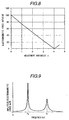
- Figure 5 shows an electromagnetic force harmonic component of the zero space degree.
- Figure 7 shows a current wave form in one phase of the stator winding 3.
- the biggest component is the zero time degree further.
- the component of zero time degree is the dc component that does not depend to the time, it acts toward the center direction with the static force, accordingly, the component of the zero time degree does not make a contribution to the oscillation.
- the sixth and the twelfth time degrees became a main component to generate the circular ring oscillation.
- the electromagnetic force drift is shown in a case that DC component of the electromagnetic force harmonic component (component of the zero time degree) and the oscillation of the electromagnetic force in the twelfth time degree are added together by considering the phase.
- F 0,0 and F 0,12 respectively means amplitudes of the electromagnetic force harmonic components respectively in the zero space degree and the zero time degree, and the zero space degree and the twelfth time degree.
- the code ⁇ 0,12 means the phase of the electromagnetic force harmonic component in the zero space degree and the twelfth time degree.
- the activation current wave form of the stator winding 3 becomes a sign wave fundamental wave form to show it in figure 7.
- the electromagnetic force harmonic component in the zero space degree and the zero time degree, and the zero space degree and the twelfth time degree is varied with the activation current of the stator winding 3.
- ⁇ ( t ) 1 - ⁇ F 0,12 F 0,0 sin(12 ⁇ t + ⁇ 0,12 )
- the electromagnetic force harmonic component of the twelfth degree mentioned above is calculated, and the variation of the electromagnetic force harmonic component for this adjustment variables ⁇ is shown in figure 8.
- a resonance frequency to be provided by an electromagnetic analysis or an experiment the electromagnetic force harmonic component which should be reduced, the time degree, the amplitude, and the phase of the harmonic component of the current, and the adjustment variables, are stored by a form such as a table etc.
- the harmonic component of the electromagnetic force has periodicity of 180/n degree in electrical angle.
- the data of the electromagnetic force harmonic are stored relating to a current-carrying section of 180/n degree in the electrical angle, they are read out repeatedly and are used to correct it in all section.
- the present embodiment has an effect as that the oscillation by the circular ring oscillation of the stator 21 and the undesired sound thereby may be reduced.
- the correction coefficient ⁇ (t) is multiplyed with a mean torque reference value Tav by a multiplier 23 so as to correct the amplitude component of the activation current, thereby to obtain a corrected torque reference Tmod, however, the corrected torque reference Tmod may be obtain by adding the correction component being equivalent to the multiplication to the mean torque reference value Tav.
- the correction signal from the correction coefficient generating circuitry 12 is added to the mean torque reference Tav so that the amplitude component of the activation current is corrected indirectly, however the correction signal from this correction coefficient generating circuitry 12 may be added directly to a two phase-three phase conversion circuitry 11, thereby the activation current is corrected as shown in figure 7.
- Figure 9 exemplifies a frequency characteristic of the oscillation amplitude.
- variable speed motor If it is done in this way, in the variable speed motor, the oscillation and teh undesired sound can be reduced in the resonance frequency, furthermore, processing load of the control system is reduced by omitting control to correct the electromagnetic force drift in the non-resonance region, it becomes possible to utilize redundant throughput for other control processings.
- slot number n spp of the stator core 17 per every pole every phase of the stator 21, is "4".
- Phase belt of the stator winding 3 of three phase is 60 degree in the electrical angle.
- the winding slot number in this phase belt is equal to n spp and it is four.
- the harmonic component of the electromagnetic force has a periodicity of 180/n degree in the electrical angle.
- the periodicity arises in every phase belt. Accordingly, if the search coils 30a to 30d is provided on four stator winding slot in one phase belt, the harmonic component of the electromagnetic force necessary for the correction control processing can be grasped by a sufficient accuracy.
- This each search coil 30 (30a to 30d) is wound more than one turn so as to surround a teeth part 17c as hown in figure 11.
- Figure 12 shows a step for the signal processing to calculate the electromagnetic force based on a variation of the magnetic flux interlinkaged with the teeth part 17c.
- this induced voltage is in proportion to a time variation of the magnetic flux which interlinkages to each teeth part 17c
- the magnetic flux density can be obtained by integrating this induced voltage signal with the time. This integral can be obtained based on digital quantity or may be used an integrating circuit.
- the electromagnetic force in the diameter direction of the stator is in proportion to square of the magnetic flux density approximately in the diameter direction, the electromagnetic force can be calculated by operating the magnetic flux density signal into square.
- Electromagnetic force data of these each teeth part 17c are developed between space, and the harmonic component of the electromagnetic force is calculated by performing an electromagnetic force harmonic operation furthermore.
- the harmonic component of the electromagnetic force that the resonance mode and the frequency accord with a dc component is extracted. These signal processing is performed in an electromagnetic force oerating unit 40 shown in figure 13.
- the correction coefficient ⁇ (t) is generated from the correction coefficient generating circuitry 12, and the amplitude component of the activation current wave form flown in the stator winding 3 is corrected by means for multiplying it to the sign wave fundamental wave form.
- an element for detecting a mechanical drift can be used as an electromagnetic force drift detecting means.
- An acceleration sensor for detecting the oscillation around the stator core or a microphone for measuring the undesired sound is provided, thereby it becomes possible to take out the harmonic component of the electromagnetic force so as to process it, by a processing technique same as the electromagnetic signal processing as mentioned above.
- the electromagnetic force harmonic component can be calculated correcponding to aged deterioration of the electric motor and the load machine, there is an effect to reduce the oscillation and the undesired sound furthermore.
Landscapes
- Engineering & Computer Science (AREA)
- Power Engineering (AREA)
- Control Of Motors That Do Not Use Commutators (AREA)
- Motor Or Generator Frames (AREA)
- Control Of Ac Motors In General (AREA)
- Control Of Electric Motors In General (AREA)
Applications Claiming Priority (3)
| Application Number | Priority Date | Filing Date | Title |
|---|---|---|---|
| JP14994198 | 1998-05-29 | ||
| JP14994198A JP3366858B2 (ja) | 1998-05-29 | 1998-05-29 | 回転電機の制御装置 |
| PCT/JP1999/002635 WO1999063654A1 (fr) | 1998-05-29 | 1999-05-19 | Dispositif de commande de moteur |
Publications (3)
| Publication Number | Publication Date |
|---|---|
| EP1087517A1 true EP1087517A1 (fr) | 2001-03-28 |
| EP1087517A4 EP1087517A4 (fr) | 2003-06-04 |
| EP1087517B1 EP1087517B1 (fr) | 2006-03-01 |
Family
ID=15485926
Family Applications (1)
| Application Number | Title | Priority Date | Filing Date |
|---|---|---|---|
| EP99921192A Expired - Lifetime EP1087517B1 (fr) | 1998-05-29 | 1999-05-19 | Dispositif de commande de moteur |
Country Status (5)
| Country | Link |
|---|---|
| US (1) | US6404152B1 (fr) |
| EP (1) | EP1087517B1 (fr) |
| JP (1) | JP3366858B2 (fr) |
| DE (1) | DE69930114T2 (fr) |
| WO (1) | WO1999063654A1 (fr) |
Cited By (4)
| Publication number | Priority date | Publication date | Assignee | Title |
|---|---|---|---|---|
| EP1211798A3 (fr) * | 2000-11-22 | 2002-09-25 | Nissan Motor Co., Ltd. | Méthode et dispositif de contrôle d'un moteur |
| WO2004055967A1 (fr) * | 2002-10-17 | 2004-07-01 | Denso Corporation | Methode d'attenuation des bruits magnetiques sur une machine electrique rotative a courant alternatif, dispositif de commande de moteur et machine electrique rotative a courant alternatif ainsi equipee |
| EP1292011A3 (fr) * | 2001-09-10 | 2005-02-02 | Nissan Motor Co., Ltd. | Commande de moteur pour réduire les harmoniques de courant |
| DE102004001932A1 (de) * | 2004-01-14 | 2005-08-11 | Minebea Co., Ltd. | Verfahren zur Ansteuerung eines elektronisch kommutierten Motors und Motorsteuerung |
Families Citing this family (26)
| Publication number | Priority date | Publication date | Assignee | Title |
|---|---|---|---|---|
| JP3499786B2 (ja) * | 1999-11-25 | 2004-02-23 | 株式会社日立製作所 | 超高速永久磁石式回転電機システム |
| US6774592B2 (en) * | 2001-12-03 | 2004-08-10 | Delphi Technologies, Inc. | Method and system for controlling a permanent magnet machine |
| JP3721368B2 (ja) * | 2003-05-23 | 2005-11-30 | ファナック株式会社 | モータ制御装置 |
| JP2005304237A (ja) | 2004-04-14 | 2005-10-27 | Denso Corp | 交流回転電機の磁気音制御方法 |
| JP4239886B2 (ja) * | 2004-04-14 | 2009-03-18 | 株式会社デンソー | 交流回転電機の磁気音制御方法 |
| JP2007043889A (ja) * | 2005-06-27 | 2007-02-15 | Denso Corp | モータ制御装置 |
| CN100461615C (zh) * | 2005-06-27 | 2009-02-11 | 株式会社电装 | 电机控制设备 |
| DE102006028331B4 (de) * | 2005-06-27 | 2019-02-14 | Denso Corporation | Motorsteuervorrichtung |
| JP2007295672A (ja) * | 2006-04-21 | 2007-11-08 | Denso Corp | モータ制御装置 |
| JP4789720B2 (ja) | 2006-07-07 | 2011-10-12 | 三洋電機株式会社 | モータ制御装置 |
| US8183814B2 (en) * | 2008-07-24 | 2012-05-22 | Ewald Franz Fuchs | Alternating current machine with increased torque above and below rated speed for hybrid electric propulsion systems |
| JP2012115044A (ja) * | 2010-11-25 | 2012-06-14 | Okuma Corp | モータの磁極位置補正方法 |
| JP5703956B2 (ja) * | 2011-05-18 | 2015-04-22 | 株式会社デンソー | 回転機の制御装置およびその製造方法 |
| US8344669B1 (en) | 2012-04-02 | 2013-01-01 | Etagen, Inc. | Methods and systems for controlling a multiphase electromagnetic machine |
| JP5648654B2 (ja) | 2012-04-23 | 2015-01-07 | 株式会社デンソー | 回転機の制御装置 |
| CN204068791U (zh) * | 2014-03-25 | 2014-12-31 | 睿能机电有限公司 | 一种无刷直流电机的电磁转矩脉动抑制装置 |
| JP6459878B2 (ja) * | 2015-09-28 | 2019-01-30 | 株式会社デンソー | 回転電機の制御装置 |
| JP6485330B2 (ja) | 2015-11-10 | 2019-03-20 | 株式会社デンソー | モータ制御装置 |
| US9819289B2 (en) | 2016-02-01 | 2017-11-14 | Denso Corporation | Control apparatus for rotating electric machine |
| JP6841018B2 (ja) * | 2016-02-01 | 2021-03-10 | 株式会社デンソー | 回転電機の制御装置 |
| JP6833077B2 (ja) * | 2018-02-08 | 2021-02-24 | 三菱電機株式会社 | 多群多相回転電機の制御装置および多群多相回転電機の駆動装置 |
| US10637386B2 (en) * | 2018-07-26 | 2020-04-28 | Enedym Inc. | Torque ripple reduction in switched reluctance machine |
| JP7323329B2 (ja) * | 2019-05-13 | 2023-08-08 | 日立Astemo株式会社 | モータ制御装置、電動パワーステアリングシステム、電動ブレーキシステム、電動車両システム |
| KR102791269B1 (ko) * | 2020-09-16 | 2025-04-08 | 현대자동차주식회사 | 차량의 사운드 생성 장치 및 방법 |
| DE102023204551A1 (de) * | 2023-05-15 | 2024-11-21 | Robert Bosch Gesellschaft mit beschränkter Haftung | Steuerungsverfahren, Kalibrierverfahren und Elektromotor |
| DE102023003920A1 (de) | 2023-09-27 | 2025-03-27 | Mercedes-Benz Group AG | Verfahren zum Betreiben eines elektrischen Antriebsstrangs und Computerprogramm |
Family Cites Families (14)
| Publication number | Priority date | Publication date | Assignee | Title |
|---|---|---|---|---|
| US4088934A (en) * | 1976-10-04 | 1978-05-09 | General Electric Company | Means for stabilizing an a-c electric motor drive system |
| JPS5413919A (en) | 1977-07-04 | 1979-02-01 | Hitachi Ltd | Preventive controller for torque pulsation |
| US4724373A (en) * | 1986-02-20 | 1988-02-09 | Wisconsin Alumni Research Foundation | Method and apparatus for flux and torque sensing in electrical machines |
| JPH01318579A (ja) * | 1988-06-16 | 1989-12-25 | Secoh Giken Inc | リラクタンス型3相電動機 |
| JPH02106192A (ja) * | 1988-10-13 | 1990-04-18 | Secoh Giken Inc | リラクタンス型電動機 |
| JPH0817585B2 (ja) * | 1989-02-06 | 1996-02-21 | 株式会社日立製作所 | トルク制御装置 |
| US5298841A (en) * | 1990-04-18 | 1994-03-29 | Hitachi, Ltd. | Apparatus for controlling the speed of a moving object |
| US5334923A (en) * | 1990-10-01 | 1994-08-02 | Wisconsin Alumni Research Foundation | Motor torque control method and apparatus |
| US5134349A (en) * | 1991-05-28 | 1992-07-28 | Kruse David L | Two-phase brushless dc motor controller |
| JPH06327285A (ja) * | 1993-05-17 | 1994-11-25 | Matsushita Electric Ind Co Ltd | モータの速度制御装置 |
| KR950015957A (ko) * | 1993-11-12 | 1995-06-17 | 이대원 | 유도 전동기의 벡터 제어방법 및 장치 |
| JP3137560B2 (ja) | 1995-05-29 | 2001-02-26 | トヨタ自動車株式会社 | 同期モータ制御装置 |
| JP3705658B2 (ja) * | 1996-09-12 | 2005-10-12 | 株式会社荏原製作所 | 半径方向力を発生する永久磁石形回転電気機械の制御システム |
| JPH10234196A (ja) * | 1997-02-19 | 1998-09-02 | Toshiba Corp | ブラシレスモータ駆動装置 |
-
1998
- 1998-05-29 JP JP14994198A patent/JP3366858B2/ja not_active Expired - Lifetime
-
1999
- 1999-05-19 EP EP99921192A patent/EP1087517B1/fr not_active Expired - Lifetime
- 1999-05-19 US US09/463,654 patent/US6404152B1/en not_active Expired - Fee Related
- 1999-05-19 DE DE69930114T patent/DE69930114T2/de not_active Expired - Fee Related
- 1999-05-19 WO PCT/JP1999/002635 patent/WO1999063654A1/fr not_active Ceased
Cited By (7)
| Publication number | Priority date | Publication date | Assignee | Title |
|---|---|---|---|---|
| EP1211798A3 (fr) * | 2000-11-22 | 2002-09-25 | Nissan Motor Co., Ltd. | Méthode et dispositif de contrôle d'un moteur |
| US6674262B2 (en) | 2000-11-22 | 2004-01-06 | Nissan Motor Co., Ltd. | Motor control apparatus and motor control method |
| EP1292011A3 (fr) * | 2001-09-10 | 2005-02-02 | Nissan Motor Co., Ltd. | Commande de moteur pour réduire les harmoniques de courant |
| WO2004055967A1 (fr) * | 2002-10-17 | 2004-07-01 | Denso Corporation | Methode d'attenuation des bruits magnetiques sur une machine electrique rotative a courant alternatif, dispositif de commande de moteur et machine electrique rotative a courant alternatif ainsi equipee |
| US7151354B2 (en) | 2002-10-17 | 2006-12-19 | Denso Corporation | Magnetic noise reduction method for AC rotary electric machine, and motor control apparatus and AC rotary electric machine apparatus using the same |
| DE102004001932A1 (de) * | 2004-01-14 | 2005-08-11 | Minebea Co., Ltd. | Verfahren zur Ansteuerung eines elektronisch kommutierten Motors und Motorsteuerung |
| DE102004001932B4 (de) * | 2004-01-14 | 2009-10-01 | Minebea Co., Ltd. | Verfahren zur Ansteuerung eines elektronisch kommutierten Motors und Motorsteuerung |
Also Published As
| Publication number | Publication date |
|---|---|
| JP3366858B2 (ja) | 2003-01-14 |
| EP1087517A4 (fr) | 2003-06-04 |
| WO1999063654A1 (fr) | 1999-12-09 |
| DE69930114D1 (de) | 2006-04-27 |
| JPH11341864A (ja) | 1999-12-10 |
| US6404152B1 (en) | 2002-06-11 |
| DE69930114T2 (de) | 2006-09-28 |
| WO1999063654A8 (fr) | 2000-02-10 |
| EP1087517B1 (fr) | 2006-03-01 |
Similar Documents
| Publication | Publication Date | Title |
|---|---|---|
| EP1087517A1 (fr) | Dispositif de commande de moteur | |
| KR100790914B1 (ko) | 회전 전자기 장치에서 토르크 불규칙성을 능동적으로감소시키는 방법 및 장치 | |
| EP0895344B1 (fr) | Méthode de commande d'ondulation du couple d'un moteur avec aimants permanents à l'intéerieur et régulateur utilisant cette méthode | |
| US5691613A (en) | Method for determining a rotor position of a rotary motor or linear motor, and circuit arrangement for carrying out the method | |
| US20020060547A1 (en) | Speed control apparatus of synchronous reluctance motor and method thereof | |
| CN1056486C (zh) | 用于修正一个无传感器的,磁场定向工作的感应式电机模型磁通的直至频率零的磁通方向的方法和装置 | |
| Hurst et al. | Speed sensorless field-oriented control of induction machines using current harmonic spectral estimation | |
| JP5795980B2 (ja) | 電動機制御装置 | |
| US20160056743A1 (en) | Motor drive control apparatus and motor drive control method | |
| US8664902B2 (en) | Polyphase AC motor, driving device and driving method therefor | |
| JP4117554B2 (ja) | モータ制御装置 | |
| US5847535A (en) | Active electronic damping for step motor | |
| JPH1155986A (ja) | 永久磁石回転電機の制御装置 | |
| EP4148973B1 (fr) | Dispositif de commande de moteur | |
| US5886493A (en) | Synchronous machine excitation control device for absorbing harmonics superposed onto fundamental current | |
| Langheck et al. | NVH optimization in PMSM through harmonic current injection with optimum current trajectory | |
| US12212190B2 (en) | Method and system to suppress tonal noises over a wide speed range in alternating current electric machines | |
| Colamartino et al. | Considerations of non-sinusoidal field distribution in a permanent magnet synchronous motor control | |
| EP4398479A1 (fr) | Commande harmonique d'ordre fractionnaire | |
| US6229277B1 (en) | Method and apparatus for the damping of motor vibrations | |
| JPH03245755A (ja) | ブラシレス自励同期発電機 | |
| EP4107852B1 (fr) | Générateur électrique synchrone et procédé de contrôle de la fréquence et de l'amplitude de la tension induite sur les enroulement du stator du générateur synchrone. | |
| JP2012050192A (ja) | モータ駆動制御装置 | |
| Antonello et al. | Torque ripple minimization in hybrid stepper motors using acceleration measurements | |
| JP2008043175A (ja) | 電動機の制御装置 |
Legal Events
| Date | Code | Title | Description |
|---|---|---|---|
| PUAI | Public reference made under article 153(3) epc to a published international application that has entered the european phase |
Free format text: ORIGINAL CODE: 0009012 |
|
| 17P | Request for examination filed |
Effective date: 20000707 |
|
| AK | Designated contracting states |
Kind code of ref document: A1 Designated state(s): DE FR GB IT |
|
| A4 | Supplementary search report drawn up and despatched |
Effective date: 20030425 |
|
| 17Q | First examination report despatched |
Effective date: 20031031 |
|
| GRAP | Despatch of communication of intention to grant a patent |
Free format text: ORIGINAL CODE: EPIDOSNIGR1 |
|
| GRAS | Grant fee paid |
Free format text: ORIGINAL CODE: EPIDOSNIGR3 |
|
| GRAA | (expected) grant |
Free format text: ORIGINAL CODE: 0009210 |
|
| RAP1 | Party data changed (applicant data changed or rights of an application transferred) |
Owner name: HITACHI, LTD. |
|
| AK | Designated contracting states |
Kind code of ref document: B1 Designated state(s): DE FR GB IT |
|
| REG | Reference to a national code |
Ref country code: GB Ref legal event code: FG4D |
|
| REF | Corresponds to: |
Ref document number: 69930114 Country of ref document: DE Date of ref document: 20060427 Kind code of ref document: P |
|
| ET | Fr: translation filed | ||
| PLBE | No opposition filed within time limit |
Free format text: ORIGINAL CODE: 0009261 |
|
| STAA | Information on the status of an ep patent application or granted ep patent |
Free format text: STATUS: NO OPPOSITION FILED WITHIN TIME LIMIT |
|
| 26N | No opposition filed |
Effective date: 20061204 |
|
| PGFP | Annual fee paid to national office [announced via postgrant information from national office to epo] |
Ref country code: DE Payment date: 20080606 Year of fee payment: 10 |
|
| PGFP | Annual fee paid to national office [announced via postgrant information from national office to epo] |
Ref country code: IT Payment date: 20080423 Year of fee payment: 10 |
|
| PGFP | Annual fee paid to national office [announced via postgrant information from national office to epo] |
Ref country code: GB Payment date: 20080424 Year of fee payment: 10 |
|
| GBPC | Gb: european patent ceased through non-payment of renewal fee |
Effective date: 20090519 |
|
| REG | Reference to a national code |
Ref country code: FR Ref legal event code: ST Effective date: 20100129 |
|
| PG25 | Lapsed in a contracting state [announced via postgrant information from national office to epo] |
Ref country code: FR Free format text: LAPSE BECAUSE OF NON-PAYMENT OF DUE FEES Effective date: 20090602 |
|
| PGFP | Annual fee paid to national office [announced via postgrant information from national office to epo] |
Ref country code: FR Payment date: 20080423 Year of fee payment: 10 |
|
| PG25 | Lapsed in a contracting state [announced via postgrant information from national office to epo] |
Ref country code: GB Free format text: LAPSE BECAUSE OF NON-PAYMENT OF DUE FEES Effective date: 20090519 |
|
| PG25 | Lapsed in a contracting state [announced via postgrant information from national office to epo] |
Ref country code: DE Free format text: LAPSE BECAUSE OF NON-PAYMENT OF DUE FEES Effective date: 20091201 |
|
| PG25 | Lapsed in a contracting state [announced via postgrant information from national office to epo] |
Ref country code: IT Free format text: LAPSE BECAUSE OF NON-PAYMENT OF DUE FEES Effective date: 20090519 |