EP1091452B1 - Connecteur électrique avec des pièces de rétention de contacts libres et moulées - Google Patents
Connecteur électrique avec des pièces de rétention de contacts libres et moulées Download PDFInfo
- Publication number
- EP1091452B1 EP1091452B1 EP00308748A EP00308748A EP1091452B1 EP 1091452 B1 EP1091452 B1 EP 1091452B1 EP 00308748 A EP00308748 A EP 00308748A EP 00308748 A EP00308748 A EP 00308748A EP 1091452 B1 EP1091452 B1 EP 1091452B1
- Authority
- EP
- European Patent Office
- Prior art keywords
- housing
- latch
- electrical connector
- molded
- latches
- Prior art date
- Legal status (The legal status is an assumption and is not a legal conclusion. Google has not performed a legal analysis and makes no representation as to the accuracy of the status listed.)
- Expired - Lifetime
Links
- 230000013011 mating Effects 0.000 claims description 43
- 238000003780 insertion Methods 0.000 description 7
- 230000037431 insertion Effects 0.000 description 7
- 239000004033 plastic Substances 0.000 description 6
- 239000002184 metal Substances 0.000 description 5
- 238000002347 injection Methods 0.000 description 3
- 239000007924 injection Substances 0.000 description 3
- 230000014759 maintenance of location Effects 0.000 description 3
- 230000000712 assembly Effects 0.000 description 2
- 238000000429 assembly Methods 0.000 description 2
- 230000007935 neutral effect Effects 0.000 description 2
- 230000002411 adverse Effects 0.000 description 1
- 238000006073 displacement reaction Methods 0.000 description 1
- 230000005489 elastic deformation Effects 0.000 description 1
- 230000001788 irregular Effects 0.000 description 1
- 239000000463 material Substances 0.000 description 1
- 239000002991 molded plastic Substances 0.000 description 1
- 230000002265 prevention Effects 0.000 description 1
Images




Classifications
-
- H—ELECTRICITY
- H01—ELECTRIC ELEMENTS
- H01R—ELECTRICALLY-CONDUCTIVE CONNECTIONS; STRUCTURAL ASSOCIATIONS OF A PLURALITY OF MUTUALLY-INSULATED ELECTRICAL CONNECTING ELEMENTS; COUPLING DEVICES; CURRENT COLLECTORS
- H01R13/00—Details of coupling devices of the kinds covered by groups H01R12/70 or H01R24/00 - H01R33/00
- H01R13/40—Securing contact members in or to a base or case; Insulating of contact members
- H01R13/42—Securing in a demountable manner
- H01R13/422—Securing in resilient one-piece base or case, e.g. by friction; One-piece base or case formed with resilient locking means
- H01R13/4223—Securing in resilient one-piece base or case, e.g. by friction; One-piece base or case formed with resilient locking means comprising integral flexible contact retaining fingers
-
- H—ELECTRICITY
- H01—ELECTRIC ELEMENTS
- H01R—ELECTRICALLY-CONDUCTIVE CONNECTIONS; STRUCTURAL ASSOCIATIONS OF A PLURALITY OF MUTUALLY-INSULATED ELECTRICAL CONNECTING ELEMENTS; COUPLING DEVICES; CURRENT COLLECTORS
- H01R13/00—Details of coupling devices of the kinds covered by groups H01R12/70 or H01R24/00 - H01R33/00
- H01R13/62—Means for facilitating engagement or disengagement of coupling parts or for holding them in engagement
- H01R13/629—Additional means for facilitating engagement or disengagement of coupling parts, e.g. aligning or guiding means, levers, gas pressure electrical locking indicators, manufacturing tolerances
- H01R13/62933—Comprising exclusively pivoting lever
- H01R13/62944—Pivoting lever comprising gear teeth
Definitions
- This invention is related to electrical connectors and especially to electrical connectors that have molded latches forming a part of a molded connector housing. These molded latches serve as primary retention members to secure electrical terminals or contacts in the housing. This invention is also related to electrical connector assemblies that use a mechanical assist, such as a lever, to overcome large mating forces between connectors having a large number of mating terminals or contacts mounted in two mating connectors.
- Crimp snap terminals are commonly used in mating electrical connectors that employ a large number of mating terminals. These terminals are first crimped to wires that may be part of an electrical harness, and the terminals are then inserted into cavities in a molded connector housing. Many of these conventional crimp snap terminals have metal tangs or lances protruding from the terminal. These tangs or lances are deflected as the terminals are inserted into the housing cavities, and the lances then snap back to their normal position engaging a surface on the connector to secure the terminals in the housing cavities after they have been completely inserted. In many applications, such as automotive and motor vehicle assemblies, these protruding metal lances pose problems.
- the protruding lances can become snagged on the wires causing difficulties during assembly, or the lances can be damaged so that they do not adequately retain the terminal in the housing.
- the mating force between terminals can then dislodge improperly seated terminals.
- tc mold resilient plastic latches as part of the molded electrical connector housing. These molded latches are typically located on one side of the housing cavities in which the terminals are positioned. When the terminals or contacts are inserted, each plastic latch is separately deflected outwardly to permit the terminal to move to its fully seated position. When the terminal is fully seated, the plastic latch can return to its neutral position where it will engage a shoulder or an edge of the terminal to retain the terminal during mating.
- US Patent 5 645 452 describes such a connector which has resilient latches molded as part of the connector housing for retaining contacts in place in cavities in the housing.
- Each latch is formed on a cavity floor separating adjacent cavities formed in the connector housing.
- the cavity floor has a hole for receiving a front end portion of the latch when the latter is flexed into a retracted position.
- a pair of ribs, each serving as a stopper, is formed on a lower surface of the cavity floor, on opposite sides of the hole, the ribs extending in a longitudinal direction.
- a gap is formed between the plastic latches and an adjacent housing wall, typically an outer housing wall.
- the adjacent wall then serves as a back-up preventing excessive deflection of the molded latch, either during terminal insertion or removal.
- a separate terminal position assurance member is then inserted into the gap between the wall and the molded latch. This terminal position assurance member can only be inserted into this gap if the terminal has been fully inserted allowing the molded latch to return to its normal position.
- the need to provide a back-up wall and a gap to provide space both for latch deflection and for insertion of a terminal position assurance member results is a larger connector by increasing the height of the housing.
- Another prior art approach that has been employed to back-up molded latches located on the exterior of the housing is to use an outer shell that fits over the external latches and is usually inserted over the mating end of the housing or from the side.
- This shell can protect the molded latches when the connector is in use, but they can only be assembled after the terminals have been fully inserted.
- the shells therefore serve as a terminal position assurance member, but they do not function as a back-up or anti-overstress member to protect the molded latches during terminal insertion or removal.
- These outer shells also add another layer with a resultant increase in the height and size of the electrical connector assembly.
- US Patent 5,322,448 discloses an electrical connector having a lever actuated mechanism for mating a connector containing receptacle contacts to. a pin header. That connector includes an outer shroud or shield to which a lever mechanism is attached. An electrical connector is fitted into a pocket in the shroud and the lever engages a rack on a mating pin header to simplify mating two multi-position electrical connectors.
- the electrical connector with which that assembly is used, employs contacts having metal lances to secure the contact in the connector housing cavities.
- that configuration requires less space than a conventional connector employing molded plastic contact retention latches.
- One of the objects of this invention is to provide an electrical connector that can fit into a shroud of a lever actuated connector assembly that is conventionally employed with terminals having metal contact retention lances.
- the invention consists in an electrical connector comprising a molded housing having a mating face at which the electrical connector is matable with a mating electrical connector, multiple electrical contacts located within cavities in the housing, molded cantilever resilient latches engaging corresponding contacts to retain the contacts in corresponding cavities, each latch being deflectable to disengage the corresponding contact, a stop shoulder on each cantilever latch adjacent a distal end of the cantilever latch and an opposed shoulder on the housing adjacent the distal end of each cantilever latch, each stop shoulder being arranged to engage its opposed shoulder to prevent overstressing of the molded cantilever latch when deflected to disengage the corresponding contact, characterised in that the stop shoulders and the opposed shoulders are located on the mating face of the housing.
- This invention is adapted to provide for overstress prevention by limiting the deflection of the plastic latch without including structure that increases the height or lateral dimension of the connector housing. It also includes anti-overstress protection for molded latches in a connector housing that can be efficiently molded.
- each latch includes a frame on the distal end which defines a portion of the cavity entrance which receives a pin of a mating headerwhen this connector is mated to the header.
- the stop shoulder on the latch is conveniently located on the side of the latch.
- the connector of the invention may be used in an electrical connector assembly that also includes an outer shroud.
- the electrical connector is positioned within the outer shroud.
- the shroud includes a lever engageable with a mating connector to apply a mating force to mate the electrical connectors.
- the housing includes the deflectable molded latches on opposed external sides of the housing. The opposed stop means on the latches and the housing prevent excessive deflection of the latches so that, by positioning the deflectable molded latches on opposed external sides of the housing, the distance between opposed external sides of the housing is reduced to fit within a shroud pocket so that the electrical connector assembly is reduced in size.
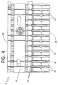
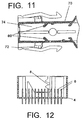
- Figure 1 shows an electrical connector assembly comprising a receptacle connector 2 which can be inserted into an outer shroud 70 so that the electrical connector 2, here containing twenty-six contacts or terminals 10 shown in Figure 3, can be mated with a mating connector, such as the header 4 shown in Figure 12.
- the shroud 70 includes a lever 72 that engages a rack 8 on header 4 to mate the contacts 10 with header pins 6.
- US Patent 5,322,448 shows a lever action connector of the same basic configuration as that depicted herein.
- the contacts or terminals 10, employed in electrical connector 2 are crimped to the ends of wires and then inserted into terminal cavities 30 in the molded housing 20. These wires are partially shown in Figure 3, and the wires are crimped to the terminals in a conventional manner.
- the contacts 10 have a mating socket 12 located at one end with a latch opening 14 located along one side of the contact.
- the mating socket 12 includes a spring beam 16, which is backed up by another beam, in the stamped and formed contact.
- a contact of this type is described in more detail in US Provisional Patent Application 60/136,719, filed May 28, 1998, which is assigned to the assignee of this application and is incorporated herein by reference.
- the molded housing 20 has two rows of housing cavities 30 into which the contacts 10 are inserted through a rear face 24 toward a housing mating face 22. Each cavity 30 extends from the rear face 24 to the mating face 22.
- the molded housing 20 has a generally rectangular cross section with laterally extending opposite housing sides 26 forming external side faces 28 which are interrupted by slots defining molded cantilevered resilient primary contact latches 50 that form a portion of the external side faces 28. These latches 50 comprise the primary latches that each secure a corresponding contact 10 in a corresponding housing cavity 30.
- Each of the cavities 30 has an open cavity entrance 36 located at the distal end of the cavity on the connector mating face 22.
- two rows of cavities 30 are formed with two rows of cavity entrances 36 located inwardly of the molded latches 50.
- openings 66 are formed adjacent each cavity entrance 36, between the cavity 30 and the external side face 28 of the injection molded connector housing 20.
- Each cavity entrance 36 is dimensioned and positioned for receipt of a header pin 6 when the connector 2 is mated to the mating header 4, shown in Figure 12..
- Each cavity entrance 36 includes beveled edges for aligning or gathering the pins when the two connectors are mated.
- the molded cantilever latches 50 form an outer side wall of the corresponding cavity 30.
- the rear end of each latch 50 is integral with the external side face 28 on which it is formed.
- the latches 50 are integral portions of the injection molded housing 20.
- the free or distal end 52 of each latch 50 is located along the housing mating face 22, and a rectangular frame 60 which is formed at the latch distal end 52 forms part of the mating face 22 and forms a portion of each corresponding cavity entrance 36.
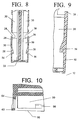
- a step or an inwardly projecting primary contact stop 56 having a shape suitable for receipt in contact latch opening 14 and is located on each latch 50 between the fixed rear end of latch and the latch distal or forward end 52. See Figures 3, 8 and 9.
- a full radiused contour 34 extends between adjacent exposed latches 50 at the base of each latch. Although these complete curved surfaces extend into the housing at the rear of the latches, and reduce the amount of material in forming the housing, lower stresses and stronger latches nevertheless result from this structure.
- the latch 50 is resilient and is deflectable when a contact 10 is inserted from the rear into the corresponding cavity 30. During insertion of the contact 10, the forward end of the contact will engage the latching step 56 and deflect the latch outward. Further forward movement of the contact 10 will bring the contact latch opening 14 into alignment with the latch step or catch 56 at which point the latch 50 will return to its normal configuration or neutral state shown in Figures 1-10. In this position, the outside of the latch 50 is in the same plane as the external side face 26 so that the latch 50 does not protrude beyond the normal mating envelope defined by the housing 20. In other words, the connector 2 can be received within the shrouded header 4 shown in Figure 12.
- stop shoulders 54 are located on the latch distal end 52. Shoulders 54 are therefore positioned to engage fixed opposed stop shoulders 40 located on the housing mating face 22 adjacent the sides of each corresponding latch 50. See Figures 6,7 and 10.
- the latch stop shoulders 54 extend beyond the sides of the latch 50 so that the latch shoulders 54 are aligned with the fixed opposed stop shoulders 40 so that the shoulders will abut upon sufficient outward deflection of the corresponding latch 50.
- the travel of the latch distal end 52 and the latch stop shoulders 54 is chosen so that the latch 50 will not be deflected beyond a point at which the latch 50 will be overstressed or damages.
- Abutting stop shoulders 54 and 40 thus serve as anti-overstress means.
- an outer wall of the housing serves as a backup preventing excess deflection of the latches, but this outer wall adds to the height or size of the connector, especially for two row connectors with two outer walls.
- the latch stop shoulders 54 located at the latch distal end 52 are formed at the two innermost corners 64 of a open rectangular frame 64 located on the latch distal end 52.
- This frame 60 includes two side columns 62 extending inwardly from the latch 50 and joining a top arm 68 extending between the inner corners 64 and the shoulders 54.
- This top arm 68 and the inner edges of the shoulders 54 form the outer portion of each cavity entrance 36.
- the top arm 68 has a beveled edge for pin alignment during mating.
- a frame central opening 66 is aligned with the latch step 52 so that the frame does not overlap the latch step 52.
- This configuration can be molded by two oppositely extending portions of an injection mold, both of which extend along the axis of the housing cavity 30, so that side pull tooling is not necessary to mold the latches 50.
- the frame 60 is separated from cavity side walls 32 by slits 42 that are located along the sides of the cavity entrances 36, but which are not large enough to allow pins 6 to enter the slits 42 during mating. See Figure 6.
- the frame opening 66 also provides space for insertion of a tool that can be used to pry or outwardly deflect the corresponding latch 50 to release the contact 10 if for any reason the contact or terminal 10 is to be removed from its housing cavity 30 or for continuity checking.
- the connector 2 When all of the contacts 10, with wires crimped to the contacts, are inserted into the housing 20, the connector 2 can be inserted through an end opening 78 of the shroud pocket 74, shown in Figures 1, 3 and 11. Ridges 80 on the inside of the shroud are received in grooves 39 on the outer sides 26 of the connector 2 when the connector 2 is inserted into the shroud or shield 70. If all of the contacts or terminals 10 are properly inserted into the corresponding housing cavities 30, the terminals will occupy the position shown in Figure 3 and the ridges 80 fit behind the contact mating socket sections 12 of all of all of the terminals.
- the ridge 80 will abut the mating section 12 of that partially inserted terminal, preventing complete insertion of connector 2 in the shroud 70.
- the shroud or shield 70 and the ridges 80 on the shroud interior surfaces thus serve as a terminal position assurance member, or TPA.
- a flexible snap on the inside of the shroud 70 engages a laterally extending arm on the housing 20 to secure the connector 2 in the shroud or shield 70.
- the stop shoulders used in the instant invention are intended to reduce the height of the connector so that it can fit within a smaller shroud, this invention can be employed in many other applications in which limiting the height of the connector is either required or desirable.
- the latch stop configuration used herein could also be used to allow multiple connectors to be mounted side by side and mated with pin terminals located in an equally spaced array. Since there is no need for a protruding structure on the exterior of the connector housing to back-up the molded latches, the adjacent exterior sides can be flush so that the spacing between adjacent rows cf pins need not be irregular.
Landscapes
- Details Of Connecting Devices For Male And Female Coupling (AREA)
- Connector Housings Or Holding Contact Members (AREA)
Claims (7)
- Connecteur électrique (2) comprenant un boítier moulé (20) comportant une face d'accouplement (22) au niveau de laquelle le connecteur électrique peut être accouplé avec un connecteur électrique complémentaire (4), de multiples contacts électriques (10) agencés dans des cavités (30) dans le boítier, des verrous élastiques moulés en porte-à-faux (50) s'engageant dans les contacts correspondants (10) pour retenir les contacts dans les cavités respectives, chaque verrou (50) pouvant être fléchi pour dégager le contact correspondant (10), un épaulement d'arrêt (54) sur chaque verrou en porte-à-faux (50), adjacent à une extrémité distale du verrou en porte-à-faux et un épaulement opposé (40) sur le boítier (20), adjacent à l'extrémité distale de chaque verrou en porte-à-faux, chaque épaulement d'arrêt (54) étant agencé de sorte à s'engager dans son épaulement opposé (40) pour empêcher une contrainte excessive du verrou moulé en porte-à-faux (50) fléchi, pour dégager le contact correspondant (10), caractérisé en ce que les épaulements d'arrêt (54) et les épaulements opposés (40) sont agencés sur la face d'accouplement (22) du boítier (20).
- Connecteur électrique selon la revendication 1, dans lequel les verrous moulés en porte-à-faux (50) sont exposés sur au moins un côté (26) du boítier (20).
- Connecteur électrique selon les revendications 1 ou 2, dans lequel les épaulements d'arrêt (54) sont agencés sur des colonnes (64) s'étendent vers l'intérieur, à l'écart du côté adjacent (26) du boítier (20).
- Connecteur électrique selon la revendication 3, dans lequel un gradin (56) s'étend vers l'intérieur sur chaque verrou (50) et s'engage dans le contact (10) agencé dans la cavité correspondante (30), chaque épaulement d'arrêt (54) étant agencé vers l'intérieur du côté de boítier adjacent (20), au-delà du gradin (56).
- Connecteur électrique selon les revendications 1 ou 2, dans lequel chaque verrou en porte-à-faux (50) englobe un cadre rectangulaire (60) agencé sur l'extrémité distale correspondante, les épaulements d'arrêt (54) étant agencés au niveau des coins (64) de chaque cadre rectangulaire (60).
- Connecteur électrique selon la revendication 5, dans lequel un gradin (56) s'étendant vers l'intérieur de chaque verrou (50) et espacé de l'extrémité distale est aligné avec une ouverture centrale (66) du cadre (60), de sorte qu'une surface avant du gradin (56) peut être moulée par un outillage de moulage s'étendant à travers l'ouverture centrale (66).
- Connecteur électrique selon la revendication 1, dans lequel chaque épaulement d'arrêt (54) s'étend à partir d'une surface latérale du verrou en porte-à-faux correspondant (50), chaque surface latérale s'étendant transversalement par rapport à un côté exposé (26) du boítier.
Applications Claiming Priority (2)
| Application Number | Priority Date | Filing Date | Title |
|---|---|---|---|
| US09/411,511 US6247966B1 (en) | 1999-10-04 | 1999-10-04 | Electrical connector with exposed molded latches |
| US411511 | 1999-10-04 |
Publications (2)
| Publication Number | Publication Date |
|---|---|
| EP1091452A1 EP1091452A1 (fr) | 2001-04-11 |
| EP1091452B1 true EP1091452B1 (fr) | 2004-04-21 |
Family
ID=23629239
Family Applications (1)
| Application Number | Title | Priority Date | Filing Date |
|---|---|---|---|
| EP00308748A Expired - Lifetime EP1091452B1 (fr) | 1999-10-04 | 2000-10-04 | Connecteur électrique avec des pièces de rétention de contacts libres et moulées |
Country Status (4)
| Country | Link |
|---|---|
| US (1) | US6247966B1 (fr) |
| EP (1) | EP1091452B1 (fr) |
| DE (1) | DE60010007T2 (fr) |
| ES (1) | ES2218073T3 (fr) |
Families Citing this family (16)
| Publication number | Priority date | Publication date | Assignee | Title |
|---|---|---|---|---|
| US6428341B2 (en) * | 2000-03-10 | 2002-08-06 | Yazaki Corporation | Inspecting jig for wire harness |
| US6402573B1 (en) * | 2001-06-07 | 2002-06-11 | Yazaki North America | Terminal position assurance device |
| DE10227347B4 (de) * | 2001-06-22 | 2009-03-05 | Sumitomo Wiring Systems, Ltd., Yokkaichi | Verbinder |
| US6736655B2 (en) * | 2002-04-17 | 2004-05-18 | Tyco Electronics Corporation | Rack and pinion electrical connector with offset gear teeth |
| JP4074776B2 (ja) * | 2002-05-07 | 2008-04-09 | 日本圧着端子製造株式会社 | ジャック |
| US7698810B2 (en) * | 2005-05-24 | 2010-04-20 | Hon Hahi Precision Ind. Co., Ltd. | Connector removal system |
| US20070135761A1 (en) * | 2005-12-09 | 2007-06-14 | Cheng Kai-Sheng | Breast pump |
| SG135994A1 (en) * | 2006-03-17 | 2007-10-29 | J S T Mfg Co Ltd | Electric connector |
| JP4904131B2 (ja) * | 2006-11-20 | 2012-03-28 | 矢崎総業株式会社 | コネクタ |
| US9033729B2 (en) * | 2012-01-26 | 2015-05-19 | Tyco Electronics Corporation | Panel mounted connector assembly |
| WO2013135849A1 (fr) * | 2012-03-16 | 2013-09-19 | Delphi Connection Systems Holding France | Connecteur électrique |
| US9142916B2 (en) * | 2013-03-15 | 2015-09-22 | Tyco Electronics Corporation | Connector assembly with receptacle carriers |
| US9142904B2 (en) * | 2014-01-14 | 2015-09-22 | Tyco Electronics Corporation | Electrical connector with terminal position assurance |
| DE102019108978A1 (de) * | 2019-04-05 | 2020-10-08 | Te Connectivity Germany Gmbh | Verbindergehäuse sowie elektrischer Verbinder |
| JP7522668B2 (ja) * | 2021-01-07 | 2024-07-25 | 日本航空電子工業株式会社 | コネクタ |
| US20240356282A1 (en) * | 2023-04-18 | 2024-10-24 | Te Connectivity Solutions Gmbh | Lever and Header Gear Tooth Engagement to Prevent Premature Connector Mating |
Family Cites Families (7)
| Publication number | Priority date | Publication date | Assignee | Title |
|---|---|---|---|---|
| US4891021A (en) | 1986-06-12 | 1990-01-02 | Amp Incorporated | High density socket contact receptacle |
| US4984998A (en) | 1989-12-15 | 1991-01-15 | Amp Incorporated | High density electrical connector |
| GB9203346D0 (en) | 1992-02-17 | 1992-04-01 | Amp Gmbh | Electrical connector assembly |
| JP2567958Y2 (ja) * | 1993-12-07 | 1998-04-08 | 住友電装株式会社 | コネクタ |
| JPH087969A (ja) * | 1994-06-17 | 1996-01-12 | Yazaki Corp | コネクタハウジング |
| JPH09115644A (ja) * | 1995-10-13 | 1997-05-02 | Yazaki Corp | 端子抜き取り治具およびコネクタハウジング |
| JPH11214062A (ja) * | 1998-01-21 | 1999-08-06 | Yazaki Corp | 二重係止コネクタ |
-
1999
- 1999-10-04 US US09/411,511 patent/US6247966B1/en not_active Expired - Fee Related
-
2000
- 2000-10-04 EP EP00308748A patent/EP1091452B1/fr not_active Expired - Lifetime
- 2000-10-04 ES ES00308748T patent/ES2218073T3/es not_active Expired - Lifetime
- 2000-10-04 DE DE60010007T patent/DE60010007T2/de not_active Expired - Lifetime
Also Published As
| Publication number | Publication date |
|---|---|
| ES2218073T3 (es) | 2004-11-16 |
| DE60010007T2 (de) | 2004-09-16 |
| DE60010007D1 (de) | 2004-05-27 |
| EP1091452A1 (fr) | 2001-04-11 |
| US6247966B1 (en) | 2001-06-19 |
Similar Documents
| Publication | Publication Date | Title |
|---|---|---|
| US4984998A (en) | High density electrical connector | |
| US6139374A (en) | Connector assembly | |
| US6247966B1 (en) | Electrical connector with exposed molded latches | |
| EP0384577B1 (fr) | Connecteur électrique pour injecteur de combustible et ses bornes | |
| EP0599165B1 (fr) | Connecteur électrique avec système d'alignement et d'arrêt en position pour éléments de contact | |
| CN111418117B (zh) | 具有端子位置保证构件的电连接器 | |
| US5993255A (en) | Electrical connector with combination terminal guide and terminal position assurance member | |
| US7841913B2 (en) | Stacked electrical connector with terminal assurance mechanism | |
| JP3995174B2 (ja) | 電気コネクタ | |
| EP1054481B1 (fr) | Un connecteur | |
| CN104253340B (zh) | 具有一体可动的端子稳定器的电连接器 | |
| US6244910B1 (en) | Electrical box contact with stress limitation | |
| US5470258A (en) | Electrical connector | |
| JPH066469Y2 (ja) | コネクタキット | |
| JPH09147948A (ja) | 電気端子及びそれを使用する電気コネクタ | |
| JP3301329B2 (ja) | コネクタ | |
| US5964621A (en) | Connector assembly for multi-pocket header | |
| EP0510229B1 (fr) | Connecteur électrique à verrouillage positif | |
| JP4162214B2 (ja) | 電気コネクタ組立体 | |
| EP0954060A2 (fr) | Connecteur électrique d'éléments de verrouillage secondaires déviables | |
| CN101218714B (zh) | 带有接线端位置保证装置的连接器组件 | |
| EP0978905B1 (fr) | Connecteur | |
| US6126484A (en) | Electrical connector with molded latch stop | |
| US7867028B2 (en) | Remote detection of partially seated electrical terminal | |
| JPH031463A (ja) | コネクタの端子係止具 |
Legal Events
| Date | Code | Title | Description |
|---|---|---|---|
| PUAI | Public reference made under article 153(3) epc to a published international application that has entered the european phase |
Free format text: ORIGINAL CODE: 0009012 |
|
| AK | Designated contracting states |
Kind code of ref document: A1 Designated state(s): CH DE ES FR GB IT LI |
|
| AX | Request for extension of the european patent |
Free format text: AL;LT;LV;MK;RO;SI |
|
| 17P | Request for examination filed |
Effective date: 20011010 |
|
| AKX | Designation fees paid |
Free format text: CH DE ES FR GB IT LI |
|
| 17Q | First examination report despatched |
Effective date: 20030508 |
|
| GRAP | Despatch of communication of intention to grant a patent |
Free format text: ORIGINAL CODE: EPIDOSNIGR1 |
|
| GRAS | Grant fee paid |
Free format text: ORIGINAL CODE: EPIDOSNIGR3 |
|
| GRAA | (expected) grant |
Free format text: ORIGINAL CODE: 0009210 |
|
| RBV | Designated contracting states (corrected) |
Designated state(s): DE ES FR GB IT |
|
| AK | Designated contracting states |
Kind code of ref document: B1 Designated state(s): DE ES FR GB IT |
|
| REG | Reference to a national code |
Ref country code: GB Ref legal event code: FG4D |
|
| REF | Corresponds to: |
Ref document number: 60010007 Country of ref document: DE Date of ref document: 20040527 Kind code of ref document: P |
|
| REG | Reference to a national code |
Ref country code: ES Ref legal event code: FG2A Ref document number: 2218073 Country of ref document: ES Kind code of ref document: T3 |
|
| ET | Fr: translation filed | ||
| PLBE | No opposition filed within time limit |
Free format text: ORIGINAL CODE: 0009261 |
|
| STAA | Information on the status of an ep patent application or granted ep patent |
Free format text: STATUS: NO OPPOSITION FILED WITHIN TIME LIMIT |
|
| 26N | No opposition filed |
Effective date: 20050124 |
|
| PGFP | Annual fee paid to national office [announced via postgrant information from national office to epo] |
Ref country code: DE Payment date: 20101027 Year of fee payment: 11 |
|
| PGFP | Annual fee paid to national office [announced via postgrant information from national office to epo] |
Ref country code: IT Payment date: 20101027 Year of fee payment: 11 Ref country code: GB Payment date: 20101025 Year of fee payment: 11 |
|
| PGFP | Annual fee paid to national office [announced via postgrant information from national office to epo] |
Ref country code: ES Payment date: 20111026 Year of fee payment: 12 Ref country code: FR Payment date: 20111028 Year of fee payment: 12 |
|
| GBPC | Gb: european patent ceased through non-payment of renewal fee |
Effective date: 20121004 |
|
| REG | Reference to a national code |
Ref country code: FR Ref legal event code: ST Effective date: 20130628 |
|
| PG25 | Lapsed in a contracting state [announced via postgrant information from national office to epo] |
Ref country code: DE Free format text: LAPSE BECAUSE OF NON-PAYMENT OF DUE FEES Effective date: 20130501 Ref country code: GB Free format text: LAPSE BECAUSE OF NON-PAYMENT OF DUE FEES Effective date: 20121004 |
|
| REG | Reference to a national code |
Ref country code: DE Ref legal event code: R119 Ref document number: 60010007 Country of ref document: DE Effective date: 20130501 |
|
| PG25 | Lapsed in a contracting state [announced via postgrant information from national office to epo] |
Ref country code: IT Free format text: LAPSE BECAUSE OF NON-PAYMENT OF DUE FEES Effective date: 20121004 Ref country code: FR Free format text: LAPSE BECAUSE OF NON-PAYMENT OF DUE FEES Effective date: 20121031 |
|
| REG | Reference to a national code |
Ref country code: ES Ref legal event code: FD2A Effective date: 20140519 |
|
| PG25 | Lapsed in a contracting state [announced via postgrant information from national office to epo] |
Ref country code: ES Free format text: LAPSE BECAUSE OF NON-PAYMENT OF DUE FEES Effective date: 20121005 |