EP1094252A2 - Zündschloss-Schaltsperre für Lenkradschalthebel-Vorrichtung - Google Patents
Zündschloss-Schaltsperre für Lenkradschalthebel-Vorrichtung Download PDFInfo
- Publication number
- EP1094252A2 EP1094252A2 EP20000122731 EP00122731A EP1094252A2 EP 1094252 A2 EP1094252 A2 EP 1094252A2 EP 20000122731 EP20000122731 EP 20000122731 EP 00122731 A EP00122731 A EP 00122731A EP 1094252 A2 EP1094252 A2 EP 1094252A2
- Authority
- EP
- European Patent Office
- Prior art keywords
- lever
- shift
- bracket
- cam
- lock
- Prior art date
- Legal status (The legal status is an assumption and is not a legal conclusion. Google has not performed a legal analysis and makes no representation as to the accuracy of the status listed.)
- Granted
Links
Images


Classifications
-
- B—PERFORMING OPERATIONS; TRANSPORTING
- B60—VEHICLES IN GENERAL
- B60R—VEHICLES, VEHICLE FITTINGS, OR VEHICLE PARTS, NOT OTHERWISE PROVIDED FOR
- B60R25/00—Fittings or systems for preventing or indicating unauthorised use or theft of vehicles
- B60R25/01—Fittings or systems for preventing or indicating unauthorised use or theft of vehicles operating on vehicle systems or fittings, e.g. on doors, seats or windscreens
- B60R25/02—Fittings or systems for preventing or indicating unauthorised use or theft of vehicles operating on vehicle systems or fittings, e.g. on doors, seats or windscreens operating on the steering mechanism
- B60R25/021—Fittings or systems for preventing or indicating unauthorised use or theft of vehicles operating on vehicle systems or fittings, e.g. on doors, seats or windscreens operating on the steering mechanism restraining movement of the steering column or steering wheel hub, e.g. restraining means controlled by ignition switch
- B60R25/02142—Fittings or systems for preventing or indicating unauthorised use or theft of vehicles operating on vehicle systems or fittings, e.g. on doors, seats or windscreens operating on the steering mechanism restraining movement of the steering column or steering wheel hub, e.g. restraining means controlled by ignition switch comprising externally controlled safety devices for preventing locking during vehicle running condition
- B60R25/02144—Fittings or systems for preventing or indicating unauthorised use or theft of vehicles operating on vehicle systems or fittings, e.g. on doors, seats or windscreens operating on the steering mechanism restraining movement of the steering column or steering wheel hub, e.g. restraining means controlled by ignition switch comprising externally controlled safety devices for preventing locking during vehicle running condition interlocked with gear box or gear lever
-
- F—MECHANICAL ENGINEERING; LIGHTING; HEATING; WEAPONS; BLASTING
- F16—ENGINEERING ELEMENTS AND UNITS; GENERAL MEASURES FOR PRODUCING AND MAINTAINING EFFECTIVE FUNCTIONING OF MACHINES OR INSTALLATIONS; THERMAL INSULATION IN GENERAL
- F16H—GEARING
- F16H59/00—Control inputs to control units of change-speed- or reversing-gearings for conveying rotary motion
- F16H59/02—Selector apparatus
- F16H59/08—Range selector apparatus
- F16H59/10—Range selector apparatus comprising levers
-
- F—MECHANICAL ENGINEERING; LIGHTING; HEATING; WEAPONS; BLASTING
- F16—ENGINEERING ELEMENTS AND UNITS; GENERAL MEASURES FOR PRODUCING AND MAINTAINING EFFECTIVE FUNCTIONING OF MACHINES OR INSTALLATIONS; THERMAL INSULATION IN GENERAL
- F16H—GEARING
- F16H61/00—Control functions within control units of change-speed- or reversing-gearings for conveying rotary motion ; Control of exclusively fluid gearing, friction gearing, gearings with endless flexible members or other particular types of gearing
- F16H61/22—Locking of the control input devices
-
- B—PERFORMING OPERATIONS; TRANSPORTING
- B60—VEHICLES IN GENERAL
- B60K—ARRANGEMENT OR MOUNTING OF PROPULSION UNITS OR OF TRANSMISSIONS IN VEHICLES; ARRANGEMENT OR MOUNTING OF PLURAL DIVERSE PRIME-MOVERS IN VEHICLES; AUXILIARY DRIVES FOR VEHICLES; INSTRUMENTATION OR DASHBOARDS FOR VEHICLES; ARRANGEMENTS IN CONNECTION WITH COOLING, AIR INTAKE, GAS EXHAUST OR FUEL SUPPLY OF PROPULSION UNITS IN VEHICLES
- B60K20/00—Arrangement or mounting of change-speed gearing control devices in vehicles
- B60K20/02—Arrangement or mounting of change-speed gearing control devices in vehicles of initiating means
- B60K20/06—Arrangement or mounting of change-speed gearing control devices in vehicles of initiating means mounted on steering column or the like
-
- Y—GENERAL TAGGING OF NEW TECHNOLOGICAL DEVELOPMENTS; GENERAL TAGGING OF CROSS-SECTIONAL TECHNOLOGIES SPANNING OVER SEVERAL SECTIONS OF THE IPC; TECHNICAL SUBJECTS COVERED BY FORMER USPC CROSS-REFERENCE ART COLLECTIONS [XRACs] AND DIGESTS
- Y10—TECHNICAL SUBJECTS COVERED BY FORMER USPC
- Y10T—TECHNICAL SUBJECTS COVERED BY FORMER US CLASSIFICATION
- Y10T70/00—Locks
- Y10T70/50—Special application
- Y10T70/5889—For automotive vehicles
- Y10T70/5925—Transmission
-
- Y—GENERAL TAGGING OF NEW TECHNOLOGICAL DEVELOPMENTS; GENERAL TAGGING OF CROSS-SECTIONAL TECHNOLOGIES SPANNING OVER SEVERAL SECTIONS OF THE IPC; TECHNICAL SUBJECTS COVERED BY FORMER USPC CROSS-REFERENCE ART COLLECTIONS [XRACs] AND DIGESTS
- Y10—TECHNICAL SUBJECTS COVERED BY FORMER USPC
- Y10T—TECHNICAL SUBJECTS COVERED BY FORMER US CLASSIFICATION
- Y10T74/00—Machine element or mechanism
- Y10T74/20—Control lever and linkage systems
- Y10T74/20012—Multiple controlled elements
- Y10T74/20018—Transmission control
- Y10T74/2014—Manually operated selector [e.g., remotely controlled device, lever, push button, rotary dial, etc.]
- Y10T74/20146—Control lever on steering column
Definitions
- the present invention relates to column shift devices for motor vehicles.
- a column shift device is a shift device mounted to a steering column for motor vehicles and having a shift lever disposed in the vicinity of a steering wheel to be rotatable, when pushing a select button, for selection of a desired shift range or position.
- the steering column is arranged with a key interlock mechanism which is a mechanism for preventing removal of a key from a key cylinder during cruising of a vehicle and allowing it only at parking (P) range.
- the key interlock mechanism is a component fully different from the column shift device, and is thus mounted to the steering column separately.
- a lock pin of the key cylinder and a key interlock lever of the column shift device are connected to each other through a cable.
- the present invention provides a column shift device, comprising:
- One aspect of the present invention lies in providing a column shift device, comprising:
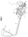
- a column shift device 1 with a key interlock mechanism comprises a jacket tube 2 and upper and lower bracket 3, 4 having respective curved portions 3a, 4a for holding the jacket tube 2, and is mounted to a steering column, not shown, through the brackets 3, 4.
- the lower bracket 4 constitutes a base, with which a key interlock mechanism is integrally formed.
- a key cylinder 5 is arranged crosswise with the lower bracket 4, and a shift lever 6 is rotatably supported thereto.
- the key cylinder 5 is a different and separate component of a predetermined standard, so that a cylindrical-shaped key cylinder frame 7 for receiving the key cylinder 5 is integrated or mounted to the lower bracket 4, and the key cylinder 5 is arranged through the key cylinder frame 7 for fixing through an appropriate means.
- the upper and lower brackets 3, 4 comprise a molding such as a die casting, and are integrated with the jacket tube 2 interposed therebetween by fastening bolts.
- the lower bracket 4 is formed with a sleeve 8 for receiving a base of the shift lever 6, and guide or support portions 11, 12 for guiding and supporting a detent plate 10 which engages or disengages from a position plate 9 perpendicularly fixed to the base of the shift lever 6.
- a unit base 53 having a key interlock mechanism 14 assembled is secured to the guide portion 11, and a groove 12a is formed with the support portion 12, with which the detent plate 10 engages.
- a shaft pin 13 protrudes from a guide face located between the support portions 11, 12 to rotatably support the detent plate 10.
- the shift lever 6 includes a pipe having one end with a knob 15 and another end with the position plate 9 mounted in the vicinity thereof, and a wire 16 passing through the inside of the pipe.
- the wire 16 has one end connected to a slide member which is in slide contact with a select button 18 within the knob 15, and another end including a ball end 19 which engages with the detent plate 10.
- the position plate 9 has a roughly fan-shaped end with a pin 20 protruding therefrom, to which a control cable for an automatic transmission is connected.
- the position plate 9 includes a stepped detent portion 21, from which one end of the detent plate 10 engages or disengages.
- the detent portion 21 is configured to correspond to shift ranges such as parking (P), rear (R), neutral (N), drive (D) and top (T) ranges.
- the one end of the detent plate 10 is shaped flat to engage or disengage from the detent portion 21, and another end is integrally formed with an engagement 22 for receiving the ball end 19, to which an adapter 23 is mounted for securing the ball end 19.
- the adapter 23 is made of a synthetic resin, and has one end with an enclosure 25 for catching the ball end 19 and another end with a bend 26 for holding and fixing the side of the detent plate 10.
- the enclosure 25 can be received in the engagement 22 of the detent plate 10.
- a shaft hole 27 is formed substantially in the center of the detent plate 10.
- the enclosure 25 of the adapter 23 having the ball end 19 received engages with the engagement 22 of the detent plate 10 to secure the adapter 23 to the detent plate 10.
- An end of a clad 16a of the wire 16 is secured, through a holder 60, to the unit base 53 fixed to the lower bracket 4.
- the shaft hole 27 of the detent plate 10 engages with the shaft pin 13 of the lower bracket 4 so that the detent plate 10 is rotatable and has both ends guided by the guide portions 11, 12. Moreover, the detent plate 10 is biased by a spring 36 in the direction that the one end of the detent plate 10 engages with the detent portion 21, so that the ball end 19 always draws the wire 16 to the column shift device 1.
- the key interlock mechanism 14 comprises a support lever 40 and a key lock lever 42, and is rotatably supported through a shaft pin 54 of the unit base 53.
- the support lever 40 is a curved lever having one end with a protrusion 44 which engages or disengages from a cam portion 33 of the cam 32, a roughly center portion with a shank 46 which receives the shaft pin 54, and another end with a contact 47 which abuts on the detent plate 10 through the bend 26 of the adapter 23.
- the key lock lever 42 is a curved lever having one end with a sleeve 48 and another end with a holder 50 for swingably supporting a lock pin 51 (see FIG. 3B, for example) which engages or disengages from the key cylinder 5.
- a protrusion 45 is formed with the support lever 40 to engage with one end of a spring 62, another end of which engages with the unit base 53 to bias the support lever 40 in the direction that the protrusion 44 always abuts on the cam portion 33 of the cam 32.
- a spring 43 is provided having one end which engages with the protrusion 45 of the support lever 40 and another end which engages with a protrusion 49 of the key lock lever 42 so as to bias the support lever 40 and the key lock lever 42 in the direction that a protrusion 44 side end of the support lever 40 and a holder 50 side end of the key lock lever 42 adjoin to each other. Since a protrusion 63, which is formed with the support lever 40 on the side of the contact 47, abuts on an end face of the key lock lever 42, the support lever 40 and the key lock lever 42 rotate together without further adjoining to each other.
- the shank 46 of the support lever 40 is coaxially fit into the sleeve 48 of the key lock lever 42, and the sleeve 48 is in turn engaged with the shaft pin 54 of the unit base 53, which is biased by the spring 43 to allow unitary rotation.
- the unit base 53 is secured to the support portion 11 of the lower bracket 4, and the shift lever 6 is held by the support lever 40 and the key lock lever 42. Then, the protrusion 44 of the support lever 40 comes in contact with the cam portion 33 of the cam 32 by a biasing force of the spring 62.
- the cam portion 33 of the cam 32 is configured such that a part is relatively low, which abuts on the protrusion 44 of the support lever 40 when the shift lever 6 is in P range, and other parts corresponding to the other ranges are relatively high.
- the support lever 40 is rotated with the key lock lever 42 by a biasing force of the spring 62.
- the cam 32 rotates with the shift lever 6, with a protrusion 34 of the inner face of a through hole engaging with a groove, not shown, of the shift lever 6.
- a protrusion 64 is integrally formed on the outer peripheral face of the cam 32.
- the shift lock mechanism comprises a solenoid 70 secured to the unit base 53, and a lock arm 72 arranged with a plunger 71 of the solenoid 70 to be capable of abutting on the detent plate 10.
- the plunger 71 of the solenoid 70 is biased by a spring 73 in the protruding direction so that the solenoid 70 has protruded plunger when the solenoid fails to be energized.
- the head of the plunger 71 abuts on the cam portion 33 of the cam 32 to have no protrusion, and the lock arm 72 fails to abut on the detent plate 10.
- the select button can be operated to engage or disengage the detent plate 10 from the detent portion 21 of the position plate 9, obtaining shift operation.
- the shift lever 6 is shifted to P range, the head of the plunger 71 is detached from the cam portion 33 to have protrusion, and the lock arm 72 is moved to the position where it can abut on the detent plate 10.
- shift lock is obtained wherein the detent plate 10 is prevented from disengaging from the detent portion 21.
- the switch 65 is actuated to allow operation of the solenoid 70, so that depression of a brake pedal, not shown, causes excitation of the solenoid 70 to draw the plunger 70, which moves the lock arm 72 to put the detent plate 10 in the rotatable state.
- a check plate 80 is secured to the position plate 9, and has a corrugated check groove 81 on the outer peripheral face formed along a circle about the shift lever 6 which is a center of rotation of the position plate 4.
- a plate spring 90 has one end fixed to the lower bracket 4, and another end formed with an U-shaped engagement 91. The U-shaped engagement 91 engages with the check groove 81 to provide a restrained feeling during shift operation of the shift lever 6.
- the protrusion 44 of the support lever 40 mounts on the cam portion 33, so that the key lever 42 is in the state that the lock pin 51 engages therewith, thus maintaining impossible removal of the key from the key cylinder 5.
- the head of the plunger 71 of the solenoid 70 abuts on the cam portion 33 to prevent protrusion of the plunger 71, so that the lock arm 72 is maintained in the position where it fails to abut on the detent plate 10, thus allowing operation of the detent plate 10 through the select button 18.
- the column shift device 1 includes a forced release mechanism for enabling shifting of the shift lever from P range even if the key is not inserted into the key cylinder 5.
- the forced release mechanism is a mechanism for forcedly shifting the lock arm 72 from the lock position where it can abut on the detent plate 10 to the lock release position where it cannot abut on the detent plate against a biasing force of the spring 73 of the solenoid 70 by using a tool, a key or the like.
- the lock arm 72 With forced release, the lock arm 72 is forcedly raised upward to move to the lock release position. And since the support lever 40 and the key lock lever 42 are wholly biased by the spring 43, the detent plate 10 can be rotated by operation of the select button 18 without abutting on the lock arm 72 and in pushing the contact 47 of the support lever 40. Thus, the detent plate 10 can disengage from the detent portion 21 to shift the shift lever 6 to any of the ranges other than P range. At that time, the key lock lever 42 is in the lock position.
- the support lever 40 and the key lock lever 42 are different and separate components.
- they may be formed integrally.
- the use of the spring 43 can be eliminated, and the forced release mechanism serves as a shift lock release mechanism for merely moving the lock arm 72 to the lock release position.
- energization release is adopted wherein when the solenoid 70 is excited, the lock arm 72 is moved to the lock release position.
- energization lock may be adopted wherein when the solenoid 70 is excited, the lock arm 72 is moved to the lock position.
- the key interlock mechanism and the shift lock mechanism are arranged on one end face of the sleeve 8 of the bracket 4 for rotatably supporting the shift lever 6, and the position plate 9 is arranged on another end face of the sleeve.
- all components may be arranged on either end face of the sleeve 8, or between two sleeves arranged in upper and lower portions .
Landscapes
- Engineering & Computer Science (AREA)
- General Engineering & Computer Science (AREA)
- Mechanical Engineering (AREA)
- Arrangement Or Mounting Of Control Devices For Change-Speed Gearing (AREA)
- Steering Controls (AREA)
- Gear-Shifting Mechanisms (AREA)
Applications Claiming Priority (2)
| Application Number | Priority Date | Filing Date | Title |
|---|---|---|---|
| JP29614499 | 1999-10-19 | ||
| JP29614499A JP2001114071A (ja) | 1999-10-19 | 1999-10-19 | キーインターロック機構付きコラムシフト装置 |
Publications (3)
| Publication Number | Publication Date |
|---|---|
| EP1094252A2 true EP1094252A2 (de) | 2001-04-25 |
| EP1094252A3 EP1094252A3 (de) | 2003-04-02 |
| EP1094252B1 EP1094252B1 (de) | 2004-09-29 |
Family
ID=17829728
Family Applications (1)
| Application Number | Title | Priority Date | Filing Date |
|---|---|---|---|
| EP20000122731 Expired - Lifetime EP1094252B1 (de) | 1999-10-19 | 2000-10-18 | Zündschloss-Schaltsperre für Lenkradschalthebel-Vorrichtung |
Country Status (4)
| Country | Link |
|---|---|
| US (1) | US6378395B1 (de) |
| EP (1) | EP1094252B1 (de) |
| JP (1) | JP2001114071A (de) |
| DE (1) | DE60014296T2 (de) |
Cited By (3)
| Publication number | Priority date | Publication date | Assignee | Title |
|---|---|---|---|---|
| DE10302050A1 (de) * | 2003-01-21 | 2004-07-29 | Daimlerchrysler Ag | Lenkradnahe Bedieneinheit mit einem schwenkbaren Lenkstockschalthebel |
| WO2008043730A1 (de) * | 2006-10-10 | 2008-04-17 | Leopold Kostal Gmbh & Co. Kg | Bedienvorrichtung für ein kraftfahrzeug mit einem bedienhebel |
| CN107269822A (zh) * | 2016-04-08 | 2017-10-20 | 现代自动车株式会社 | 手动变速器的换挡杆组件 |
Families Citing this family (4)
| Publication number | Priority date | Publication date | Assignee | Title |
|---|---|---|---|---|
| JP2001113978A (ja) | 1999-10-19 | 2001-04-24 | Fuji Kiko Co Ltd | コラム式シフト装置のハンドレバー構造 |
| JP3934358B2 (ja) * | 2001-03-28 | 2007-06-20 | 富士機工株式会社 | シフトレバー装置 |
| DE10131433B4 (de) * | 2001-06-29 | 2010-09-09 | Daimler Ag | Schaltvorrichtung für ein Kraftfahrzeuggetriebe |
| USD495725S1 (en) | 2003-03-12 | 2004-09-07 | Samyeong Cable Co., Ltd. | Locking clamp for automotive change gear cable |
Citations (1)
| Publication number | Priority date | Publication date | Assignee | Title |
|---|---|---|---|---|
| JPH11296144A (ja) | 1998-04-08 | 1999-10-29 | Fujitsu Ltd | 液晶表示装置の駆動回路 |
Family Cites Families (5)
| Publication number | Priority date | Publication date | Assignee | Title |
|---|---|---|---|---|
| JP2520861Y2 (ja) * | 1989-06-26 | 1996-12-18 | 株式会社東海理化電機製作所 | コラムタイプの自動変速機用シフトレバーのロック装置 |
| US5299470A (en) * | 1992-12-21 | 1994-04-05 | Chrysler Corporation | Ignition interlock mechanism for a column-mounted shift control assembly |
| US5647465A (en) * | 1996-03-14 | 1997-07-15 | General Motors Corporation | Transmission shift lever and brake interlock control assembly |
| JP3666835B2 (ja) * | 1996-08-09 | 2005-06-29 | 万能工業株式会社 | コラムat用シフトレバー装置 |
| JP3671194B2 (ja) | 1996-08-09 | 2005-07-13 | 万能工業株式会社 | コントロールレバーの固定機構 |
-
1999
- 1999-10-19 JP JP29614499A patent/JP2001114071A/ja active Pending
-
2000
- 2000-10-05 US US09/679,607 patent/US6378395B1/en not_active Expired - Fee Related
- 2000-10-18 DE DE2000614296 patent/DE60014296T2/de not_active Expired - Fee Related
- 2000-10-18 EP EP20000122731 patent/EP1094252B1/de not_active Expired - Lifetime
Patent Citations (1)
| Publication number | Priority date | Publication date | Assignee | Title |
|---|---|---|---|---|
| JPH11296144A (ja) | 1998-04-08 | 1999-10-29 | Fujitsu Ltd | 液晶表示装置の駆動回路 |
Cited By (4)
| Publication number | Priority date | Publication date | Assignee | Title |
|---|---|---|---|---|
| DE10302050A1 (de) * | 2003-01-21 | 2004-07-29 | Daimlerchrysler Ag | Lenkradnahe Bedieneinheit mit einem schwenkbaren Lenkstockschalthebel |
| WO2008043730A1 (de) * | 2006-10-10 | 2008-04-17 | Leopold Kostal Gmbh & Co. Kg | Bedienvorrichtung für ein kraftfahrzeug mit einem bedienhebel |
| CN107269822A (zh) * | 2016-04-08 | 2017-10-20 | 现代自动车株式会社 | 手动变速器的换挡杆组件 |
| CN107269822B (zh) * | 2016-04-08 | 2020-06-19 | 现代自动车株式会社 | 手动变速器的换挡杆组件 |
Also Published As
| Publication number | Publication date |
|---|---|
| EP1094252A3 (de) | 2003-04-02 |
| US6378395B1 (en) | 2002-04-30 |
| JP2001114071A (ja) | 2001-04-24 |
| DE60014296T2 (de) | 2005-02-24 |
| EP1094252B1 (de) | 2004-09-29 |
| DE60014296D1 (de) | 2004-11-04 |
Similar Documents
| Publication | Publication Date | Title |
|---|---|---|
| EP0437985B1 (de) | Brems-/Schaltsperre für die Schaltsteuerung eines automatischen Getriebes | |
| US6783480B2 (en) | Control device for automatic transmission | |
| EP0459417B1 (de) | Schalteinrichtung eines automatischen Getriebes | |
| US5207740A (en) | Control device for automatic transmission | |
| JPH08338513A (ja) | シフトレバー装置のシフトロック機構 | |
| US6194676B1 (en) | Turn signal switch device | |
| US6378395B1 (en) | Column shift device with key interlock mechanism | |
| JPH07266908A (ja) | シフトレバー装置 | |
| EP0939251B1 (de) | Schalthebel | |
| JP4004855B2 (ja) | 自動変速機操作装置のシフトロック機構 | |
| US6339968B1 (en) | Shift lever apparatus | |
| US5431267A (en) | Lock release apparatus | |
| JP3934358B2 (ja) | シフトレバー装置 | |
| US6443026B1 (en) | Shift lever operating apparatus for automatic transmission | |
| JP4751648B2 (ja) | 車両用シフトロック装置 | |
| KR19980032879A (ko) | 변속 레버 장치 | |
| US6308814B1 (en) | Parking lock mechanism for gate type automatic transmission shift control device | |
| US5542512A (en) | Selector device for an automatic transmission system provided with locking means | |
| US6427503B2 (en) | Key interlock mechanism for column automatic-transmission operating device | |
| US6345521B1 (en) | Shift lock mechanism for shift lever | |
| JP4847653B2 (ja) | 自動変速機用シフト装置 | |
| JPH0630528Y2 (ja) | セレクタレバー装置 | |
| JPH0744848Y2 (ja) | 車両用シフトロック装置 | |
| JPH08200480A (ja) | 車両用自動変速機のシフトロック装置 | |
| JPH06344786A (ja) | 自動変速機を備えた車両のシフトロック装置 |
Legal Events
| Date | Code | Title | Description |
|---|---|---|---|
| PUAI | Public reference made under article 153(3) epc to a published international application that has entered the european phase |
Free format text: ORIGINAL CODE: 0009012 |
|
| 17P | Request for examination filed |
Effective date: 20001018 |
|
| AK | Designated contracting states |
Kind code of ref document: A2 Designated state(s): AT BE CH CY DE DK ES FI FR GB GR IE IT LI LU MC NL PT SE |
|
| AX | Request for extension of the european patent |
Free format text: AL;LT;LV;MK;RO;SI |
|
| PUAL | Search report despatched |
Free format text: ORIGINAL CODE: 0009013 |
|
| AK | Designated contracting states |
Kind code of ref document: A3 Designated state(s): AT BE CH CY DE DK ES FI FR GB GR IE IT LI LU MC NL PT SE Designated state(s): AT BE CH CY DE DK ES FI FR GB GR IE IT LI LU MC NL PT SE |
|
| AX | Request for extension of the european patent |
Extension state: AL LT LV MK RO SI |
|
| 17Q | First examination report despatched |
Effective date: 20030811 |
|
| AKX | Designation fees paid |
Designated state(s): DE FR GB |
|
| GRAP | Despatch of communication of intention to grant a patent |
Free format text: ORIGINAL CODE: EPIDOSNIGR1 |
|
| GRAS | Grant fee paid |
Free format text: ORIGINAL CODE: EPIDOSNIGR3 |
|
| GRAA | (expected) grant |
Free format text: ORIGINAL CODE: 0009210 |
|
| AK | Designated contracting states |
Kind code of ref document: B1 Designated state(s): DE FR GB |
|
| REG | Reference to a national code |
Ref country code: GB Ref legal event code: FG4D |
|
| PGFP | Annual fee paid to national office [announced via postgrant information from national office to epo] |
Ref country code: FR Payment date: 20041020 Year of fee payment: 5 |
|
| PGFP | Annual fee paid to national office [announced via postgrant information from national office to epo] |
Ref country code: GB Payment date: 20041025 Year of fee payment: 5 |
|
| REG | Reference to a national code |
Ref country code: IE Ref legal event code: FG4D |
|
| REF | Corresponds to: |
Ref document number: 60014296 Country of ref document: DE Date of ref document: 20041104 Kind code of ref document: P |
|
| PGFP | Annual fee paid to national office [announced via postgrant information from national office to epo] |
Ref country code: DE Payment date: 20041126 Year of fee payment: 5 |
|
| ET | Fr: translation filed | ||
| PLBE | No opposition filed within time limit |
Free format text: ORIGINAL CODE: 0009261 |
|
| STAA | Information on the status of an ep patent application or granted ep patent |
Free format text: STATUS: NO OPPOSITION FILED WITHIN TIME LIMIT |
|
| 26N | No opposition filed |
Effective date: 20050630 |
|
| PG25 | Lapsed in a contracting state [announced via postgrant information from national office to epo] |
Ref country code: GB Free format text: LAPSE BECAUSE OF NON-PAYMENT OF DUE FEES Effective date: 20051018 |
|
| PG25 | Lapsed in a contracting state [announced via postgrant information from national office to epo] |
Ref country code: DE Free format text: LAPSE BECAUSE OF NON-PAYMENT OF DUE FEES Effective date: 20060503 |
|
| GBPC | Gb: european patent ceased through non-payment of renewal fee |
Effective date: 20051018 |
|
| PG25 | Lapsed in a contracting state [announced via postgrant information from national office to epo] |
Ref country code: FR Free format text: LAPSE BECAUSE OF NON-PAYMENT OF DUE FEES Effective date: 20060630 |
|
| REG | Reference to a national code |
Ref country code: FR Ref legal event code: ST Effective date: 20060630 |