EP1096459A2 - Système d'évitement de collision - Google Patents
Système d'évitement de collision Download PDFInfo
- Publication number
- EP1096459A2 EP1096459A2 EP00309507A EP00309507A EP1096459A2 EP 1096459 A2 EP1096459 A2 EP 1096459A2 EP 00309507 A EP00309507 A EP 00309507A EP 00309507 A EP00309507 A EP 00309507A EP 1096459 A2 EP1096459 A2 EP 1096459A2
- Authority
- EP
- European Patent Office
- Prior art keywords
- vehicle
- crossing
- driver
- bumping
- road
- Prior art date
- Legal status (The legal status is an assumption and is not a legal conclusion. Google has not performed a legal analysis and makes no representation as to the accuracy of the status listed.)
- Granted
Links
Images


Classifications
-
- G—PHYSICS
- G08—SIGNALLING
- G08G—TRAFFIC CONTROL SYSTEMS
- G08G1/00—Traffic control systems for road vehicles
- G08G1/16—Anti-collision systems
- G08G1/164—Centralised systems, e.g. external to vehicles
Definitions
- the present invention relates to an bumping prevention system which is used, for instance, in the field of traffic signal control and prevents bumping between a vehicle running in a non-priority road and a vehicle running in a priority road at a crossing between the two roads by transacting signals with on-road infrastructure in a service area between fixed point information detection support facility for service-in installed at a point by a specified distance away from the crossing on the non-priority road and a fixed point information detection support facility for service-out installed at a point near the crossing.
- the bumping prevention system is a system for preventing bumping between a vehicle running on a non-priority road and a vehicle running on a priority road at a crossing between the two roads by transacting signals with on-road infrastructure in a service area between a fixed point information detection support facility for service-in installed at a point away by a specified distance from the crossing on the non-priority road and a fixed point information detection support facility for service-out installed at a position near the crossing, and when a vehicle passes by the fixed point detection support facility for service-in and enters the service area, the vehicle recognizes availability of providing information, alarms, and control for prevention of expected bumping at a crossing upon reception of a signal indicating entry into a service area from the support facilities, and starts computing of a position of the current by recognizing a distance between the current running position of the vehicle and a priority road.
- the system When the vehicle receives information concerning vehicles on a priority road from the on-road infrastructure and recognized that a vehicle just about to enter the crossing is present on the priority road, the system provides information concerning the crossing as well as the vehicle just about to enter the crossing at a point away by a distance enough to decelerate and stop the vehicle by the crossing, and further when it is determined that there is the possibility of collision between the vehicle running on the non-priority road and the vehicle running on the priority road and just about to enter the crossing, the system gives an alarm indicating the possibility of bumping to a driver of the vehicle running on the non-priority road. Further when it is expected that there is the possibility of bumping between the vehicle and another vehicle running on the priority road and entering the crossing, the system continuously provides controls for emergently decelerating or stopping the vehicle in front of the crossing.
- the bumping prevention system is a system for preventing bumping between a vehicle running on a non-priority road and a vehicle running on a priority road at a crossing between the two roads by transacting signals with on-road infrastructure in a service area between a fixed point information detection support facility for service-in installed at a point away by a specified distance from the crossing on the non-priority road and a fixed point information detection support facility for service-out installed at a position near the crossing, and when a vehicle passes by the fixed point information detection facility for service-in and enters the service area, the vehicle receives a signal indicating start of the service area from the support facility and recognizes the availability of information provision service for preventing expected bumping after restart.
- the vehicle When the vehicle stops in front of the crossing, the vehicle obtains information concerning vehicles on a priority road from the on-road infrastructure and if the vehicle recognizes presence of a pedestrian or a vehicle just about to enter the crossing on a priority road, information indicating presence of the pedestrian or vehicle is given to the driver.
- the bumping prevention system is a system for preventing bumping between a vehicle running on a non-priority road and a vehicle running on a priority road at a crossing between the two roads by transacting signals with on-road infrastructure in a service area between a fixed point information detection support facility for service-in installed at a point away by a specified distance from the crossing on the non-priority road and a fixed point information detection support facility for service-out installed at a position near the crossing, and when a vehicle passes by a fixed point information detection support facility for service-in and enters a service area, the vehicle recognizes availability of the service for providing information, alarms, and controls for prevention of bumping when the vehicle accesses a crossing or availability of the information provision service for prevention of expected bumping after the vehicle once stops in front of the crossing and then restarts upon reception of a signal indicating start of the service area from the support facilities, and starts computing a position of the vehicle by grasping the distance from the running position of the vehicle
- the system When the vehicle obtains information concerning vehicles on the priority road from the on-road infrastructure and recognizes that a vehicle just about to enter the crossing is present on the priority road, the system provides information concerning the crossing as well as presence of the vehicle just entering the crossing on the priority road to the driver at a point where the driver can decelerate and stop the vehicle in front of the crossing. Further when it is determined that there is the possibility of bumping with the vehicle just entering the crossing, this system gives an alarm indicating the possibility of bumping to the driver at a point where the driver can brake and stop the vehicle in an emergency in front of the crossing.
- the system continuously provides controls for support in braking in a range from a point where the driver can brake and stop the vehicle in front of the crossing up to a point just in front of the crossing.
- the system obtained information concerning vehicles on the priority road and gives to the driver information concerning the vehicle, if any.
- Fig. 1 is a block diagram showing general configuration of this system, and in the system shown in the figure, the number of each facility may vary according to a point where the facility is installed or a monitoring range for the on-road facility, but a number of facility is not an important factor. Also the input/output data in this figure indicates only those essentially required in this system.
- on-road facility as the on-road infrastructure constituting the system as well as of facilities loaded on an AHS car as an example of vehicle are described.
- AHS is an abbreviation of Advanced-cruise-assist Highway System indicating a road system enabling automatic driving of vehicles
- the AHS car indicating a car which can automatically be controlled by the Advanced-cruise-assist Highway System.
- the on-road facilities of this system comprises a fixed point information detection support facilities 1, 2 provided on a non-priority road, and a vehicle detection facility 3, an on-road processing facility 4, an on-road database 6, and a road-to-vehicle communications facility 6 each provided on a priority road, and functions of each facility are as described below.
- the fixed point information detection support facilities 1, 2 are facilities used in a pair with a fixed point information detection sensor 8 loaded on the AHS car 7, and the AHS car 7 having passed the fixed point information detection support facility 1 installed at a specified position on the road can recognize a service-in point, a type of the provided service, and a service-out point.
- the vehicle detection facility 3 detects behaviors (such as a position and a velocity) of vehicles (including two-wheel vehicles) running on a priority road.
- the on-road processing facility (including the running support information preparation facility) 4 is a computing/processing unit as a main device among the on-road facilities for this service, and the facility 4 executes operations mainly for processing input/output data and preparing output data.
- the on-road database 5 is a database in which data required for the service is stored, and in this system information concerning road line form of objective priority roads and non-priority roads.
- the system provides the information when accessed by the on-road processing facility 4.
- the road-to-vehicle communications facility 6 executes communications between the on-road facilities and a vehicle, and in this system the road-to-vehicle communications facility 6 provides mainly information concerning vehicles on a priority road and information concerning road line form to the AHS car 7.
- Devices 11 loaded on the AHS car 7 includes a fixed point information detection sensor 8, an AHS car position detection sensor 12, a road-to-vehicle communications device 13, a peripheral situation detection sensor 14, an AHS car state detection sensor 15, and an on-vehicle processing unit 16, and functions of each device is as described below.
- the fixed point information detection sensor is a facility used as a pair with the fixed point information detection support facility 1, and detects such factors as a type of available service, a service area length, and service-out or the like when the vehicle passes by the fixed point information support facility 1 installed at a specified position on the road.
- the AHS car position detection sensor 12 detects a position of the AHS car based on the information from the fixed point information detection support facility 1.
- the road-to-vehicle communications device 13 controls communications between on-road facilities and vehicles.
- the peripheral situation detection sensor 14 detects a situation around the AHS car.
- the AHS car state detection sensor 15 detects a velocity, acceleration or the like of the AHS car.
- the on-vehicle processing device (including also the computing/processing unit) 16 is a device which collects information required for the AHS car and executes processing such as provision of information, computing, and determination, and in this system the on-vehicle processing device 16 provides information concerning presence of a vehicle entering a crossing, determines the possibility of bumping, and gives an instruction for alarm to the on-vehicle HMI (Human Machine Interface) 17 and a control instruction value to the vehicle control unit 18 when it is determined that there is the possibility of bumping.
- HMI Human Machine Interface
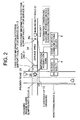
- Fig. 2 shows a crossing 9 (without any alarm) between a non-priority road 22 with a stop line 21 provided thereon and a priority road 23, and this figure shows an example in which a priority road with two lanes to which the present invention is applied and a non-priority road with one lane.
- Fig. 2 assumes that the fixed point information detection support facility 1 for service-in installed at a point P 1 away by a specified point (for instance, 40 m) from the crossing 9 can recognize a service-in point, a service-out point, an area length, and a type of available service.
- the AHS car 7 passes by the point P 1 and enters the service area 24, the AHS car recognizes availability of the service for providing information, alarms, and controls for prevention of bumping during access to the crossing 9, grasps a running position of the AHS car and a distance up to a priority road, and starts computing for a position of the AHS car.
- the AHS car 7 having reached the point P 1 activates the service for providing information, alarms, and controls for prevention of bumping and immediately start acquisition of the information concerning vehicles running on the priority road 23 from the on-road infrastructure.
- the information concerning vehicles on the priority road 23 is transmitted at a prespecified cycle (typically at a cycle of 0.1 second) through the road-to-vehicle communications facility 6.
- the AHS car 7 in the service area 24 continues to run and passes through the crossing 9, the AHS car 7 determines whether there is the possibility of collision of the AHS car with another vehicle 25 running on the priority road 23.
- Fig. 2 shows an example of determination on the possibility of collision of the AHS car with the vehicle 25 from the upstream side of the priority road 23 at the crossing 9.
- it is required only to check how the time zone in which the vehicle approaching the crossing 9 from the upstream side of the priority road 23 resides on the crossing overlaps with the time zone in which the AHS car 7 resides within the crossing 9. Namely, if the two time zones overlaps with each other, it is determined that there is the possibility of collision, and if the two time zones do not overlap with each other, it is determined that there is not the possibility of collision.
- the AHS car 7 can determine the possibility of collision by assuming a constant acceleration pattern (including a uniform velocity movement) and also assuming that the vehicle 25 approaching from the upstream side of the priority road 23 to the crossing continues to run at the current velocity measured at the current point detected by the vehicle detection facility 3.
- an alarm is generated, and at the same time controls are provided to control running of the vehicle with the vehicle control unit 18.
- the AHS car receives information concerning vehicles just about to enter the crossing.
- the fixed point information detection support facility 2 installed at the point p 2 is for enabling detection of service out, and provision of the service is finished when the AHS car 7 has passed over this point.
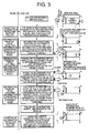
- Fig. 3 is an explanatory view showing a scenario in this bumping prevention system, and is a flow chart showing the operations described above.
- Fig. 4 is a time chart for the bumping prevention system centering on the on-road processing facility 4 at the crossing shown in Fig. 2.
- input to the on-road processing facility in this system is information concerning a velocity and a position of a vehicle on the priority road 23.
- Information concerning vehicles on the priority road 23 is inputted once for every 0.1 second from the vehicle detection facility 3, and is stored in the on-road database 5.
- the on-road processing facility 4 prepares information to be transmitted to the AHS vehicle 7 once for every 0.1 second.
- Fig. 5 and Fig. 6 show processing flows by the on-road processing facility 4 at the crossing shown in Fig. 2.
- Fig. 5 shows a flow of processing a data concerning a position and a velocity of the vehicle 25 on the priority road 23 detected by the vehicle detection facility 3. The processing is executed once for every 0.1 second, and the data is stored as data 1 indicating a position and a velocity of the detected vehicle and a time of detection of the data in the on-road database 5.
- Fig. 6 shows a processing flow for preparation of output data to be sent to the ASH car 7. This processing is executed once for every 0.1 second, and the prepared output data is once stored in the on-road database 5. The stored output data is transmitted from the road-to-vehicle communications facility 6 to the AHS car 7. The information concerning a velocity and a position of the vehicle 25 on the priority road 23 detected by the vehicle detection facility 3 is used for determination of the possibility of bumping.
- Fig. 7 is a time chart of the processing for computing a range of management by the on-road facility on the bumping prevention system shown in Fig. 2, and mainly shows the AHS car and the driver's operations.
- the bumping prevention system has the vehicle detection facility 3 installed on the priority road 23 and the fixed information detection support facilities 1, 2 installed on a non-priority road.
- the bumping prevention system mainly computes a range of monitoring by the vehicle detection facility 3 for monitoring the vehicle 25 running on the priority road 23 toward the crossing 9 and a range of communications for a vehicle to be serviced.
- the total time T k from a point of time when a driver of the AHS car 7 running on a non-priority road 22 recognizes presence of a vehicle 25 entering a crossing on the priority road and brakes the AHS car 7 until the point of time when the AHS car 7 stops in front of the stop line is computed.
- a distance L 1 between the crossing 9 and the vehicle at the distal point can be obtained by multiplying the total time T k by the maximum velocity V of the vehicle 25.
- T 3 T 2 + T 1 + T 0
- T 2 is a period of time from the point when the driver recognizes a situation on the priority road 23 until a point of time when the driver determines the possibility of bumping
- T 1 is a period of time required for changing a foot position from the accelerator to the brake
- T 0 is a period of time required for actually stepping on the accelerator.
- T 5 V ⁇ + T 4 2
- the range of communications is 40 m when the first digit is rounded up.
Landscapes
- Physics & Mathematics (AREA)
- General Physics & Mathematics (AREA)
- Traffic Control Systems (AREA)
- Control Of Driving Devices And Active Controlling Of Vehicle (AREA)
- Emergency Alarm Devices (AREA)
- Alarm Systems (AREA)
Applications Claiming Priority (2)
| Application Number | Priority Date | Filing Date | Title |
|---|---|---|---|
| JP30509599A JP3484492B2 (ja) | 1999-10-27 | 1999-10-27 | 出合い頭衝突防止システム |
| JP30509599 | 1999-10-27 |
Publications (3)
| Publication Number | Publication Date |
|---|---|
| EP1096459A2 true EP1096459A2 (fr) | 2001-05-02 |
| EP1096459A3 EP1096459A3 (fr) | 2002-07-24 |
| EP1096459B1 EP1096459B1 (fr) | 2006-04-19 |
Family
ID=17941053
Family Applications (1)
| Application Number | Title | Priority Date | Filing Date |
|---|---|---|---|
| EP20000309507 Expired - Lifetime EP1096459B1 (fr) | 1999-10-27 | 2000-10-27 | Système d'évitement de collision |
Country Status (3)
| Country | Link |
|---|---|
| EP (1) | EP1096459B1 (fr) |
| JP (1) | JP3484492B2 (fr) |
| DE (1) | DE60027384T2 (fr) |
Cited By (5)
| Publication number | Priority date | Publication date | Assignee | Title |
|---|---|---|---|---|
| CN104903172A (zh) * | 2012-10-05 | 2015-09-09 | 雷诺股份公司 | 用于评估在交叉路口的碰撞风险的方法 |
| CN107867290A (zh) * | 2017-11-07 | 2018-04-03 | 长春工业大学 | 一种考虑运动障碍物的汽车紧急避撞分层式控制方法 |
| CN110799387A (zh) * | 2017-07-11 | 2020-02-14 | 株式会社电装 | 车辆中的制动辅助装置以及制动辅助控制方法 |
| CN110956789A (zh) * | 2019-12-19 | 2020-04-03 | 业成科技(成都)有限公司 | 智慧行动装置测距系统及其方法 |
| CN111201556A (zh) * | 2017-10-06 | 2020-05-26 | 本田技研工业株式会社 | 车辆控制装置 |
Families Citing this family (8)
| Publication number | Priority date | Publication date | Assignee | Title |
|---|---|---|---|---|
| WO2002103652A1 (fr) * | 2001-06-14 | 2002-12-27 | Fujitsu Limited | Systeme d'intersection et procede de communication d'informations de vehicule a l'interieur dudit systeme |
| JP2006301842A (ja) * | 2005-04-19 | 2006-11-02 | Honda Motor Co Ltd | 車両の運転支援装置 |
| JP2007293388A (ja) * | 2006-04-20 | 2007-11-08 | Toyota Motor Corp | 交差点交通管制システム |
| JP4623145B2 (ja) * | 2008-06-16 | 2011-02-02 | トヨタ自動車株式会社 | 運転支援装置 |
| JP4939564B2 (ja) | 2009-03-23 | 2012-05-30 | 本田技研工業株式会社 | 車両用情報提供装置 |
| JP6677178B2 (ja) * | 2017-01-13 | 2020-04-08 | トヨタ自動車株式会社 | 運転支援装置 |
| JP2019153029A (ja) * | 2018-03-02 | 2019-09-12 | 本田技研工業株式会社 | 車両制御装置 |
| CN108922167B (zh) * | 2018-05-23 | 2020-10-09 | 中国汽车技术研究中心有限公司 | 一种基于dsrc的紧急车辆智能交通控制系统和方法 |
Family Cites Families (10)
| Publication number | Priority date | Publication date | Assignee | Title |
|---|---|---|---|---|
| JPH0528400A (ja) * | 1991-07-24 | 1993-02-05 | Matsushita Electric Ind Co Ltd | 車両の出合い衝突防止表示装置 |
| JPH0546897A (ja) * | 1991-08-09 | 1993-02-26 | Omron Corp | 衝突防止装置 |
| JPH0644498A (ja) * | 1992-07-23 | 1994-02-18 | Mazda Motor Corp | 車両の情報伝達装置 |
| JPH1153685A (ja) * | 1997-07-31 | 1999-02-26 | Toyota Motor Corp | 合流支援装置 |
| JP3592043B2 (ja) * | 1997-07-31 | 2004-11-24 | トヨタ自動車株式会社 | 交差点警報装置 |
| JPH1153686A (ja) * | 1997-07-31 | 1999-02-26 | Toyota Motor Corp | 交差点警報装置 |
| JPH11110700A (ja) * | 1997-09-29 | 1999-04-23 | Toyota Motor Corp | 交差点情報提供システム及びそのシステムに適用される車載情報送信装置 |
| JP3687306B2 (ja) * | 1997-09-30 | 2005-08-24 | トヨタ自動車株式会社 | 車載交差点情報提供装置 |
| JP3857402B2 (ja) * | 1997-12-05 | 2006-12-13 | 富士通株式会社 | 交差点衝突防止方法及びシステム及び交差点衝突防止プログラムを格納した記憶媒体及び交差点装置 |
| JPH11328598A (ja) * | 1998-05-18 | 1999-11-30 | Toyota Motor Corp | 交差点警報システム |
-
1999
- 1999-10-27 JP JP30509599A patent/JP3484492B2/ja not_active Expired - Lifetime
-
2000
- 2000-10-27 DE DE2000627384 patent/DE60027384T2/de not_active Expired - Lifetime
- 2000-10-27 EP EP20000309507 patent/EP1096459B1/fr not_active Expired - Lifetime
Cited By (8)
| Publication number | Priority date | Publication date | Assignee | Title |
|---|---|---|---|---|
| CN104903172A (zh) * | 2012-10-05 | 2015-09-09 | 雷诺股份公司 | 用于评估在交叉路口的碰撞风险的方法 |
| CN104903172B (zh) * | 2012-10-05 | 2017-08-08 | 雷诺股份公司 | 用于评估在交叉路口的碰撞风险的方法 |
| CN110799387A (zh) * | 2017-07-11 | 2020-02-14 | 株式会社电装 | 车辆中的制动辅助装置以及制动辅助控制方法 |
| CN111201556A (zh) * | 2017-10-06 | 2020-05-26 | 本田技研工业株式会社 | 车辆控制装置 |
| CN111201556B (zh) * | 2017-10-06 | 2022-06-24 | 本田技研工业株式会社 | 车辆控制装置 |
| CN107867290A (zh) * | 2017-11-07 | 2018-04-03 | 长春工业大学 | 一种考虑运动障碍物的汽车紧急避撞分层式控制方法 |
| CN107867290B (zh) * | 2017-11-07 | 2019-07-12 | 长春工业大学 | 一种考虑运动障碍物的汽车紧急避撞分层式控制方法 |
| CN110956789A (zh) * | 2019-12-19 | 2020-04-03 | 业成科技(成都)有限公司 | 智慧行动装置测距系统及其方法 |
Also Published As
| Publication number | Publication date |
|---|---|
| EP1096459A3 (fr) | 2002-07-24 |
| DE60027384D1 (de) | 2006-05-24 |
| EP1096459B1 (fr) | 2006-04-19 |
| JP3484492B2 (ja) | 2004-01-06 |
| JP2001126198A (ja) | 2001-05-11 |
| DE60027384T2 (de) | 2007-02-01 |
Similar Documents
| Publication | Publication Date | Title |
|---|---|---|
| EP1096458B1 (fr) | Système pour éviter une collision sur un carrefour | |
| US6360171B1 (en) | Bumping prevention system | |
| JP3174832B2 (ja) | 横断歩行者衝突防止システム | |
| US10697790B2 (en) | Lane selecting device, vehicle control system and lane selecting method | |
| EP1104881B1 (fr) | Système de commande de véhicule | |
| JP6206120B2 (ja) | 合流支援システム | |
| US5521580A (en) | Danger avoidance system for a vehicle | |
| CN111951569B (zh) | 一种绿波通行方法和装置 | |
| EP1096459A2 (fr) | Système d'évitement de collision | |
| CN113830105A (zh) | 交叉路口辅助驾驶方法、车辆及计算机可读存储介质 | |
| EP1096460A2 (fr) | Système pour empêcher des collisions entre un véhicule et un obstacle | |
| JP3740524B2 (ja) | 走行支援道路システム | |
| CN115273461A (zh) | 车辆的路口行驶方法、装置、车辆及存储介质 | |
| JPH09311996A (ja) | カー・ナビゲーション装置 | |
| JPH1125391A (ja) | 交通信号警告システム | |
| JP3453599B2 (ja) | 出会頭衝突防止支援方法 | |
| JP3488913B2 (ja) | 出会頭衝突防止支援情報提供・警報・制御方法 | |
| KR20040037423A (ko) | 디 에스 알 씨를 이용한 지능형 서비스 장치 및 방법 | |
| EP4325462B1 (fr) | Procédé de détection d'une manoeuvre de virage large d'un véhicule, procédé de fonctionnement d'un véhicule autonome, appareil de traitement de données, programme informatique et support de stockage lisible par ordinateur | |
| CN113160612A (zh) | 一种车辆预警系统 | |
| CN113823122A (zh) | 一种基于5g的v2x信号机 | |
| JP3562375B2 (ja) | 車両走行制御装置 | |
| JP6076109B2 (ja) | 運転支援装置 | |
| JP2002264748A (ja) | ブレーキ操作量及びタイミングの提供方法 | |
| JP3720716B2 (ja) | 料金収受システム用車載器 |
Legal Events
| Date | Code | Title | Description |
|---|---|---|---|
| PUAI | Public reference made under article 153(3) epc to a published international application that has entered the european phase |
Free format text: ORIGINAL CODE: 0009012 |
|
| 17P | Request for examination filed |
Effective date: 20001228 |
|
| AK | Designated contracting states |
Kind code of ref document: A2 Designated state(s): AT BE CH CY DE DK ES FI FR GB GR IE IT LI LU MC NL PT SE |
|
| AX | Request for extension of the european patent |
Free format text: AL;LT;LV;MK;RO;SI |
|
| RIN1 | Information on inventor provided before grant (corrected) |
Inventor name: MURAKAMI, HIDEAKI, C/O OMRON CORPORATION Inventor name: YAMADA, MASAYA, C/O SUMITOMO ELECTRIC IND., LTD. Inventor name: NOGUCHI, NAOYA Inventor name: MOTEKI, SATOSHI, C/O ISUZU MOTORS LIMITED Inventor name: TAKIGUCHI, AKIHIKO, C/O NEC CORPORATION Inventor name: KUBOTA, KOJI, C/O NIPPON TELEGRAPH & TELEPHONE CO Inventor name: OOYA, HARUTADA, C/O OKI ELECTRIC INDUSTRY CO.,LTD Inventor name: TAKAHASHI, HIROSHI, C/O NISSAN MOTOR CO., LTD. |
|
| PUAL | Search report despatched |
Free format text: ORIGINAL CODE: 0009013 |
|
| AK | Designated contracting states |
Kind code of ref document: A3 Designated state(s): AT BE CH CY DE DK ES FI FR GB GR IE IT LI LU MC NL PT SE |
|
| AX | Request for extension of the european patent |
Free format text: AL;LT;LV;MK;RO;SI |
|
| RAP1 | Party data changed (applicant data changed or rights of an application transferred) |
Owner name: DIRECTOR GENERAL OF NATIONAL INSTITUTE FOR LAND AN |
|
| AKX | Designation fees paid |
Designated state(s): DE FR GB IT |
|
| 17Q | First examination report despatched |
Effective date: 20031030 |
|
| GRAP | Despatch of communication of intention to grant a patent |
Free format text: ORIGINAL CODE: EPIDOSNIGR1 |
|
| RIN1 | Information on inventor provided before grant (corrected) |
Inventor name: OHIRA, YASUYUKI,C/O FUJITSU LIMITED Inventor name: KAWAHARA, KAZUTAKA,C/O MITSUBISHI ELECTRIC CORP. Inventor name: TAKAHASHI, HIROSHI,C/O NISSAN MOTOR CO., LTD. Inventor name: KUNO, AKIRA,C/O DENSO CORPORATION Inventor name: KUBOTA, KOJI,C/O NIPPON TELEGRAPH & TELEPHONE Inventor name: EZURE, HISASHI,C/O TOSHIBA CO., Inventor name: OOYA, HARUTADA,C/O OKI ELECTRIC INDUSTRY CO.,LTD. Inventor name: MOTEKI, SATOSHI,C/O ISUZU MOTORS LIMITED Inventor name: TAKIGUCHI, AKIHIKO,C/O NEC CORPORATION Inventor name: MATSUBARA, RYOJI,C/O HITACHI CABLE, LTD. Inventor name: MURAKAMI, HIDEAKI,C/O OMRON CORPORATION Inventor name: KONDO, TETSUAKI,C/O HITACHI, LTD. Inventor name: INOBE, TAKAO,C/O MATSUSHITA ELECTRIC IND.CO.LTD. Inventor name: OHTANI, KENICHI,C/O THE FURUKAWA ELECTRIC CO.LTD. Inventor name: NOGUCHI, NAOYA Inventor name: MIYAMOTO, KAZUMASA,C/O MITSUBISHI HEAVY IND.,LTD. Inventor name: MASHIMO, HIROSHI,C/O HONDA MOTOR CO., LTD. Inventor name: YAMADA, MASAYA,C/O SUMITOMO ELECTRIC IND., LTD. |
|
| GRAS | Grant fee paid |
Free format text: ORIGINAL CODE: EPIDOSNIGR3 |
|
| GRAA | (expected) grant |
Free format text: ORIGINAL CODE: 0009210 |
|
| AK | Designated contracting states |
Kind code of ref document: B1 Designated state(s): DE FR GB IT |
|
| PG25 | Lapsed in a contracting state [announced via postgrant information from national office to epo] |
Ref country code: IT Free format text: LAPSE BECAUSE OF FAILURE TO SUBMIT A TRANSLATION OF THE DESCRIPTION OR TO PAY THE FEE WITHIN THE PRESCRIBED TIME-LIMIT;WARNING: LAPSES OF ITALIAN PATENTS WITH EFFECTIVE DATE BEFORE 2007 MAY HAVE OCCURRED AT ANY TIME BEFORE 2007. THE CORRECT EFFECTIVE DATE MAY BE DIFFERENT FROM THE ONE RECORDED. Effective date: 20060419 |
|
| REG | Reference to a national code |
Ref country code: GB Ref legal event code: FG4D |
|
| REF | Corresponds to: |
Ref document number: 60027384 Country of ref document: DE Date of ref document: 20060524 Kind code of ref document: P |
|
| ET | Fr: translation filed | ||
| PLBE | No opposition filed within time limit |
Free format text: ORIGINAL CODE: 0009261 |
|
| STAA | Information on the status of an ep patent application or granted ep patent |
Free format text: STATUS: NO OPPOSITION FILED WITHIN TIME LIMIT |
|
| 26N | No opposition filed |
Effective date: 20070122 |
|
| REG | Reference to a national code |
Ref country code: FR Ref legal event code: PLFP Year of fee payment: 16 |
|
| REG | Reference to a national code |
Ref country code: FR Ref legal event code: PLFP Year of fee payment: 17 |
|
| REG | Reference to a national code |
Ref country code: FR Ref legal event code: PLFP Year of fee payment: 18 |
|
| REG | Reference to a national code |
Ref country code: FR Ref legal event code: PLFP Year of fee payment: 19 |
|
| PGFP | Annual fee paid to national office [announced via postgrant information from national office to epo] |
Ref country code: DE Payment date: 20191021 Year of fee payment: 20 |
|
| PGFP | Annual fee paid to national office [announced via postgrant information from national office to epo] |
Ref country code: FR Payment date: 20191018 Year of fee payment: 20 Ref country code: IT Payment date: 20191023 Year of fee payment: 20 |
|
| PGFP | Annual fee paid to national office [announced via postgrant information from national office to epo] |
Ref country code: GB Payment date: 20191024 Year of fee payment: 20 |
|
| REG | Reference to a national code |
Ref country code: DE Ref legal event code: R071 Ref document number: 60027384 Country of ref document: DE |
|
| REG | Reference to a national code |
Ref country code: GB Ref legal event code: PE20 Expiry date: 20201026 |
|
| PG25 | Lapsed in a contracting state [announced via postgrant information from national office to epo] |
Ref country code: GB Free format text: LAPSE BECAUSE OF EXPIRATION OF PROTECTION Effective date: 20201026 |