EP1097775A2 - Vorrichtung zur Winkelstellung eines Brenners - Google Patents
Vorrichtung zur Winkelstellung eines Brenners Download PDFInfo
- Publication number
- EP1097775A2 EP1097775A2 EP00106791A EP00106791A EP1097775A2 EP 1097775 A2 EP1097775 A2 EP 1097775A2 EP 00106791 A EP00106791 A EP 00106791A EP 00106791 A EP00106791 A EP 00106791A EP 1097775 A2 EP1097775 A2 EP 1097775A2
- Authority
- EP
- European Patent Office
- Prior art keywords
- arm
- rotation shaft
- angle
- torch
- rotation
- Prior art date
- Legal status (The legal status is an assumption and is not a legal conclusion. Google has not performed a legal analysis and makes no representation as to the accuracy of the status listed.)
- Withdrawn
Links
Images


Classifications
-
- B—PERFORMING OPERATIONS; TRANSPORTING
- B23—MACHINE TOOLS; METAL-WORKING NOT OTHERWISE PROVIDED FOR
- B23K—SOLDERING OR UNSOLDERING; WELDING; CLADDING OR PLATING BY SOLDERING OR WELDING; CUTTING BY APPLYING HEAT LOCALLY, e.g. FLAME CUTTING; WORKING BY LASER BEAM
- B23K26/00—Working by laser beam, e.g. welding, cutting or boring
- B23K26/08—Devices involving relative movement between laser beam and workpiece
- B23K26/0869—Devices involving movement of the laser head in at least one axial direction
- B23K26/0876—Devices involving movement of the laser head in at least one axial direction in at least two axial directions
- B23K26/0884—Devices involving movement of the laser head in at least one axial direction in at least two axial directions in at least three axial directions, e.g. manipulators, robots
-
- B—PERFORMING OPERATIONS; TRANSPORTING
- B23—MACHINE TOOLS; METAL-WORKING NOT OTHERWISE PROVIDED FOR
- B23K—SOLDERING OR UNSOLDERING; WELDING; CLADDING OR PLATING BY SOLDERING OR WELDING; CUTTING BY APPLYING HEAT LOCALLY, e.g. FLAME CUTTING; WORKING BY LASER BEAM
- B23K10/00—Welding or cutting by means of a plasma
-
- B—PERFORMING OPERATIONS; TRANSPORTING
- B23—MACHINE TOOLS; METAL-WORKING NOT OTHERWISE PROVIDED FOR
- B23K—SOLDERING OR UNSOLDERING; WELDING; CLADDING OR PLATING BY SOLDERING OR WELDING; CUTTING BY APPLYING HEAT LOCALLY, e.g. FLAME CUTTING; WORKING BY LASER BEAM
- B23K7/00—Cutting, scarfing, or desurfacing by applying flames
- B23K7/10—Auxiliary devices, e.g. for guiding or supporting the torch
- B23K7/102—Auxiliary devices, e.g. for guiding or supporting the torch for controlling the spatial relationship between the workpieces and the gas torch
Definitions
- the present invention relates to a torch-angle setting device which is advantageously used together with a cutting device for carrying out the groove-angle cutting of material being cut by gas cutting torch, plasma cutting torch or laser cutting torch.
- a cutter for the groove-angle cutting of material being cut is explained.
- gas cutting torch, plasma cutting torch or laser cutting torch is selectively used in a genaral way.
- a torch is inclined at the cutting angle and this cutting angle is kept until the objective groove-angle cutting is finished. Therefore, when material being cut is cut with groove angle into a curved line, a torch-angle setting device is formed in such a manner that a torch can be turned so that the direction of torch is coincided with a normal line of curved line.
- a position of as a standard of control in the case where cutting is made is the intersection of the extension of line of a torch and material being cut, wherein a locus of the intersection coincides with an objective design. Accordingly, it is not a problem of utmost importance whether the intersection of the extension of line of a torch and material being cut coincides with the intersection of the extension of line of a turning shaft and material being cut, of as a reference of when turning the torch, or not. Therefore, as a torch in which the two intersections are not coincided with each other, an offset system machining head has been formed and as a torch in which the two intersections are coincided with each other, a zero offset system machining head has been formed, and programs corresponding to the respective machining heads have been provided.
- the mechanism for setting torch-angle is generally formed in such a manner that a torch can be set at a desired angle by mounting a torch holder for holding a torch on a carriage which moves along a fan-shaped guide, and moving the carriage by means of a motor.
- the turning of torch is carried out by turning the fan-shaped guide, wherein zero offset system machining head can be realized by keeping the fan-shaped guide away from the turning shaft, and by coinciding the torch with the turning shaft.
- the torch is provided with the mechanism for inclining the torch at the objective inclining angle and with the mechanism for coinciding straight-passing laser beam with an inclined angle of torch while reflecting laser beam.
- a torch-angle setting device comprises a turning shaft which is arranged perpendicularly to material being cut, a first rotation shaft which is arranged at right angle to the turning shaft and which has an end connected with the turning shaft, a second rotation shaft which is arranged in parallel with the first rotation shaft, a first arm which is connected with the first rotation shaft and with the second rotation shaft, a second arm which has an end connected with the second rotation shaft, a driving means for rotating the first arm on the first rotation shaft and rotating the second arm, by an angle which is twice as much as the angle of rotation of the first arm, on the second rotation shaft in the opposite direction to the direction of rotation of the first arm, along with the rotation of the first rotation shaft, said second arm being substantially formed as a torch.
- the first rotation shaft is arranged perpendicularly to the turning shaft, an end of the first rotation shaft is connected with the turning shaft, the second rotation shaft is arranged in parallel with the first rotation shaft, and these rotation shafts are connected through the first arm.
- angle made between the first arm and the extension of line of the turning shaft is equals to with an angle made between the second arm and the extension of line of the turning shaft, seeing from the direction of extension of line of each of the rotation shafts, and the intersection of the extension of line of the turning shaft and the extension of line of the second arm is positioned on the turning shaft.
- the torch can be set at the same angle as that of the first angle, by setting the first angle to the extension of line of the turning shaft at a desired angle.
- the driving means is comprised of a first fixed member which is fixed to the first rotation shaft and has the preset diameter, a second fixed member which is fixed to the second arm which is arranged on the extension of line of the second rotation shaft and has substantially an diameter of 1/2 of the diameter of the first fixed member, and a transmitting member connected with the first fixed member and with the second fixed member, and a rotating member which rotates the first rotation shaft or the second arm.
- toothed pulleys or sprocket wheels can be used.
- the transmitting member a middle gear, a toothed belt or a chain can be preferably used. And by selecting the fixed member and the transmitting member from among the above-mentioned parts, the secure driving without slippage can be realized.
- the combination of a V pulley and a V belt, or the combination of pulleys and flat belt may be applied.
- the device is preferably formed in such a manner that the when first arm is rotated on the first rotation shaft and the second arm is rotated on the second rotation axis, the extension of line of the second arm intersects the extension of line of the turning shaft.
- the second arm has a laser torch in which laser beam can pass
- the turning shaft, the first rotation shaft, the second rotation shaft, and the first arm are formed of tubes, respectively, and light path is formed within the turning shaft, the first rotation shaft, the second rotation shaft, and the first arm.
- Each of angle setting devices A, B according the first and second embodiment is formed as a torch for laser-cutting, wherein each of the devices A and B is formed in such a manner that it is preferably mounted on the numerically-controlled laser cutting machine C so as to be advantageously used, shown in Fig. 5.
- the principle of the present invention can be applied not only for the laser cutting machine, but also for the numerically-controlled laser cutting machine having a torch such as gas cutting torch and plasma cutting torch mounted thereon, without altering the structure of the angle setting device.
- a typical example of the numerically-controlled(NC) laser cutting machine C is briefly explained.
- a truck 52 is illustrated which is put on a pair of rails 51 laid parallel to each other so as to be movable.
- This truck 52 is comprised of a saddle 52a arranged along a rail 51 and girder 52b arranged meeting at right angle to a direction of the rail 51.
- a lateral movement carriage 53 is put on the girder 52b so that the lateral movement carriage 53 is movable in the direction meeting at right angle to the laid direction of rail 51.
- the angle setting device A is put on the lateral movement carriage 53.
- a laser oscillator 54 is put on the saddle 52 so that a light path 55 is formed between the laser oscillator 54 and the angle setting device A.
- This light path 55 is comprised of tube which pass laser beam and a plurality of mirrors so that a given length of the light path 55 can be maintained notwithstanding a change in a length of from the laser oscillator 54 to the angle setting device A.
- a numerically-controlled(NC) device is provided at a given place within the saddle 52a.
- a control board 56 provided with an input unit such as a key board and with a display unit such as a Braun tube is provided on the outer surface of the saddle 52a.
- a step 57 corresponding to the control board 56 is formed integrally with the saddle 52a.
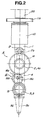
- numeral "1" designates a turning shaft, which is arranged perpendiculary to the surface of material being cut.
- Numeral "2" designates a first rotation shaft, which is arranged at right angle to the first rotation shaft 1, and which has an end connected with the turning shaft 1.
- Numeral "3" designates a second rotation shaft, which is arranged parallel with the first rotation shaft 2.
- Numeral "4" designates a first arm, which connects the first rotation shaft 2 with the second rotation shaft 3, and which is rotatable on the first rotation shaft .
- Numeral "5" designates a second arm, which is rotatable on the second rotation shaft 3, and which is formed substantially as a torch.
- the second arm 5 may be formed as a torch in such a manner as in the undermentioned first and second embodiments. Further, the second arm 5 may be formed as an arm provided with a torch holder for attaching gas cutting torch and plasma cutting torch. Further, zero-offset system can be formed by coinciding the axial center of the second arm 5 or the extention thereof 5a ( hereinafter referred to as "the extention of line” ) with an axial center of the turning shaft 1 or the extention thereof ( hereinafter referred to as "the extention of line” ) by adjusting lengths of the first rotation shaft 2 and the second rotation shaft 3, or offset system can be formed without coinciding the two with each other.
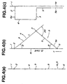
- the first arm 4 is turned by angle ⁇ in the direction of arrow a on the first rotation shaft 2, while the second arm 5 is turned, by angle 2 ⁇ which is two times as much as the turning angle ⁇ of the first arm 4, in the direction of arrow b which is the opposite direction to the turning direction of the first arm 4, on the second rotation shaft 3, .
- an angle made by the first arm 4 and the second arm 5 becomes 180° ⁇ 2 ⁇ , so that an angle made by the extention of line 5a of the first arm 5 and the extention of line 1a of the turning shaft 1 becomes ⁇ , wherein the second arm (torch) can be set at the objective groove angle ⁇ .
- the intersection (in case of offset system, observed intersection) 6 of the extention of line 5a of the second arm 5 and the extention of line 1a of the turning shaft 1 moves in the direction of arrow c (upward) along the extention of line 1a of the turning shaft 1.
- a triangle formed by the extaention of line 1a of the turning shaft 1, the first arm 4, the second arm 5 and the extention of line 5a of the second arm 5 becomes equilateral triangle. Accordingly, even if any angle of the first arm 4 is set, an angle of the second arm 5 to the extention of line 1a of the turning shaft 1 can be made an angle which is the same as that of the first arm 4. Namely, a torch-angle can be set.
- intersection 6 moves in the direction of arrow c along the extention of line 1a of the turning shaft 1 in case of setting the angle of the second arm 5
- a distance of from the turning center of the first arm 5 (the intsersection of the fisrst rotation shaft 2 and the first arm 4 ) to the intersection 6 can be calculated as 2L cos ⁇ under the condition where a length of the first arm 4 is L and an angle of the first arm to the extention 1a of the turning shaft 1 is ⁇ .
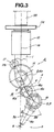
- Numeral "1" designates a turning shaft arranged perpendicularly to the surface of material being cut (not shown)
- numeral “2” desinates a first rotation shaft which is arranged at right angle to the turning shaft 1, and which has an end connected with the turning shaft 1
- numeral "3” designates a second rotation shaft which is arranged parallel with the first rotation shaft
- numeral "4" designates a first arm which is provided on the first rotation shaft 2 so as to rotatable on the first rotation shaft 2 and which has an end formed as the second rotation shaft 3
- Numeral "5" designates a second arm which is provided on the second rotation shaft 3 so as to be rotatable on the second rotation shaft 3 and is subatantially a torch.
- the turning shaft 1 is formed as a tube comprised of a vertical main body 1b and an orthogonally bent portion formed at the lower end of the main body 1b.
- a tubular body forming a light path 55 of laser beam within it is connected with the upper side of the main body 1b.
- the turning shaft 1 is rotatably supported on a bearing unit 10, wherein a rotary gear 11a is held to the turning shaft 11a at a given position thereof.
- a frame forming the bearing unit 10 or a NC laser cutting machine C is mounted with a motor 11c with a gear 11b whcih is engaged with the rotary gear 11a. Therefore, the second arm 5 (torch) can be turned on the turning shaft 1 by motor 11c according to the state of curved line of a cutting form with the advance of cutting of material being cut.
- the bent portion 1c formed at the lower end of the main body 1b forming the turning shaft 1 is formed as a first rotation shaft 2. Therefore, the first rotation shaft 2 is set at right angle to the turning axis 1, while an end of the first rotation shaft 2 is connected with the turning shaft 1.
- the first arm 4 is formed as a tube which has a shape of " " and which is comprised of an upper bent portion 4a, a main body 4b, and a second rotation shaft 3 connected with the lower end of the main body 4b.
- the upper bent portion 4a is engaged with the first rotation shaft 2 to be rotatable on the first rotation shaft 2, by which the first arm 4 is formed so as to be rotatable on the first rotation shaft 2.
- a length of the first arm 4 ( a length of the main body 4b ) is nor restricted. However, it is preferable to be as short as possible for miniaturizing the angle setting device A.
- the second arm 5 is formed as a tube comrised of a main body 5b, and a bent portion 5c formed at the upper end of the main body 5b at right angle to the main body 5b, wherein the bent portion 5c is engaged with the second rotation shaft 3 so as to be rotatble on the second rotation shaft 3, and the main body 5b is formed as a torch ( hereinafter referred to as "torch 5b").
- the whole shape formed of the the turning axis 1, the first arm 4, and the second arm 5 is formed into a shape of crank, the respective corner portions are provided with mirrors 12 to 12d, and further, the second arm 5 is provided with lens 13. Therefore, laser beam sent through a light path 55 is reflected by the respective mirrors 12a to 12d, condensed through lans 13, and applied for material being cut from the torch 5b.
- a first fixed gear 14 as a first fixed member is fixed to the periphery of the first rotation shaft 2, while a second fixed gear 15 as a second fixed member is fixed to the periphery of the second arm 5.
- These first and second gears are formed so as to have substantially the relation between the two that the ratio of diameters of the first and second fixed gears is 2 : 1.
- a middle gear 16 as a transmitting member is arranged between the two fixed gears, wherein a small gear 16a of the middle gear is engaged with the first fixed gear 14, while a large gear 16b of the middle gear is engaged with the second fixed gear 15, so that the first fixed gear 14 and the second fixed gear 15 can be rotated and a rotation axis 16c is provided with the first arm 4.
- a motor 17 as rotating member is provided around the periphery of the upper bent portion 4a of the first arm 4, and a gear 17 attached to the motor 17 is engaged with the first fixed gear 14, so that the gear 17a can be rotated along the periphery of the first fixed gear 14.
- the gear 17 When the gear 17 is driven by the motor 17, the gear 17 is rotated along the periphery of the first fixed gear 14 in the direction of arrow a, because the first fixed gear 14 is fixed to the first rotation shaft 2, while along with this rotation of the gear 17a, the first arm 4 is rotated on the first rotation shaft 2 in the direction of arrow a. Therefor, the rotation axis 16c is moved in the direction of arrow a, while along with the movement of the rotation shaft 16c, the small gear 16a moves around the first fixed gear 14 with rotating on its own axis. Accordingly, the large gear 16b makes the same rotation as that of the small gear 16a, and this rotation is transmitted to the second fixed gear 16.
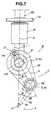
- a first pulley 21 as a first fixed member is fixed to a first rotation shaft 2, while a second pulley 22 as a second second member is fixed to the periphery of the second arm 5.
- These first pulley 21 and the second pulley 22 are formed so as to have substantially the relation between the two that the ratio of diameters of the first and second fixed gears is 2 : 1, wherein the two is connected with each other through a belt 23 as transmitting member.
- a gear 24 forming a rotation member is fixed to the first rotation shaft 2, while a motor 17 as a rotation member is provided around the periphery of the upper bent portion 4a.
- a gear 17a attached to the motor 17 is engated with the gear 24 so that the gear 17a can be rotated along the periphery of the gear 24.
- the second arm 5 can be set to angle ⁇ which makes possible to carry out the groove angle cutting.
- a main body 5b of a second arm 5 is formed as a laser cutting torch.
- the main body of the second arm 5 is provided with a torch holder, in which gas cutting torch 5b or a plasma cutting torch is held, the setting of torch-angle is also possible without altering.
- a first rotation shaft 2 is arranged at right angle to a turning shaft 1
- a second rotation shaft 3 is arranged parallel with the first rotation shaft 1
- the first rotation shaft 2 and second rotation shaft 3 are connected through a first arm 4, and along with rotating the first rotation shaft 2 by means of a driving means, and the second arm 5 is rotated, by angle which is twice as much as an angle of rotation of the first arm 4 against the first arm 4, in the opposite direction to the direction of rotation of the first arm 4, an angle made between the first arm 4 and the extension of line 1a of a turning shaft 1 is equal to an angle made between the second arm 5 and the extension of line 1a of a turning shaft 1, seeing from the direction of the extension of line of the respective rotation shafts. Therefore, when the second arm 5 is used substantially as a torch, the torch can be set at the same angle as that of the first arm 4 to the extension of line 1a of a turning shaft 1.
- first fixed member 4 a first fixed gear 14 or a first pulley 21
- a transmitting member belt 23
- second fixed member a second fixed gear 15 or a second pulley 22
- the angle setting device includes a second arm 5 as a laser torch, and a turning shaft 1, a first rotation shaft 2, a second rotation shaft 3 and a first arm 4 are formed with tubes, respectively, in which a light path for for passing laser beam is formed, each shaft of the turning shaft 1, the first rotation shaft 2, the second rotation shaft 3 and the first arm 4 and the light path formed within the individual shaft are used in common so that a laser cutting torch can with a brief structure can be formed.
Landscapes
- Engineering & Computer Science (AREA)
- Physics & Mathematics (AREA)
- Optics & Photonics (AREA)
- Mechanical Engineering (AREA)
- Plasma & Fusion (AREA)
- Robotics (AREA)
- Arc Welding In General (AREA)
- Laser Beam Processing (AREA)
- Manipulator (AREA)
Applications Claiming Priority (2)
| Application Number | Priority Date | Filing Date | Title |
|---|---|---|---|
| JP31478799A JP2001129675A (ja) | 1999-11-05 | 1999-11-05 | トーチの角度設定装置 |
| JP31478799 | 1999-11-05 |
Publications (2)
| Publication Number | Publication Date |
|---|---|
| EP1097775A2 true EP1097775A2 (de) | 2001-05-09 |
| EP1097775A3 EP1097775A3 (de) | 2002-01-23 |
Family
ID=18057596
Family Applications (1)
| Application Number | Title | Priority Date | Filing Date |
|---|---|---|---|
| EP00106791A Withdrawn EP1097775A3 (de) | 1999-11-05 | 2000-03-30 | Vorrichtung zur Winkelstellung eines Brenners |
Country Status (3)
| Country | Link |
|---|---|
| US (1) | US6333487B1 (de) |
| EP (1) | EP1097775A3 (de) |
| JP (1) | JP2001129675A (de) |
Cited By (4)
| Publication number | Priority date | Publication date | Assignee | Title |
|---|---|---|---|---|
| EP1762328A1 (de) * | 2005-09-09 | 2007-03-14 | Highyag Lasertechnologie GmbH | Taktil geführte Laserbearbeitungsoptik |
| WO2007048183A1 (en) * | 2005-10-26 | 2007-05-03 | Jason Andrew Macey | Pivotable fluid connector |
| AT16218U1 (de) * | 2016-04-28 | 2019-03-15 | Wieser Automation Maschb Gmbh | Vorrichtung zur führung eines laserstrahls auf ein werkstück |
| CN111730202A (zh) * | 2020-04-15 | 2020-10-02 | 苏州普热斯勒先进成型技术有限公司 | 激光切割模组及装置 |
Families Citing this family (7)
| Publication number | Priority date | Publication date | Assignee | Title |
|---|---|---|---|---|
| JP2005515720A (ja) * | 2002-01-11 | 2005-05-26 | ポートレイト・イノヴェイションズ,インコーポレイテッド | ポートレートを作成するシステムおよび方法 |
| US7074112B2 (en) * | 2003-03-21 | 2006-07-11 | Omax Corporation | Apparatus that holds and tilts a tool |
| US8097204B2 (en) * | 2009-11-12 | 2012-01-17 | Koike Aronson, Inc. | Bevel head attachment for plasma and oxy fuel cutting machines |
| EP2732902B1 (de) * | 2012-11-16 | 2017-05-03 | Kjellberg-Stiftung | Verfahren zum Plasmaschneiden von Werkstücken mit einem geneigten Plasmastrahl |
| CN104972212B (zh) * | 2014-04-10 | 2017-05-03 | 蔡道德 | 一种隔热防辐射自动电焊钳 |
| US11554461B1 (en) | 2018-02-13 | 2023-01-17 | Omax Corporation | Articulating apparatus of a waterjet system and related technology |
| WO2021127253A1 (en) | 2019-12-18 | 2021-06-24 | Hypertherm, Inc. | Liquid jet cutting head sensor systems and methods |
Family Cites Families (12)
| Publication number | Priority date | Publication date | Assignee | Title |
|---|---|---|---|---|
| US2468938A (en) * | 1945-06-14 | 1949-05-03 | Houdaille Hershey Corp | Torch controlling fixture for flame cutting machines |
| US3619550A (en) * | 1969-09-25 | 1971-11-09 | Laser Systems Corp | Laser beam machine tool with beam manipulating apparatus |
| US4205828A (en) * | 1978-08-28 | 1980-06-03 | C-R-O, Inc. | Cutting of contour bevels |
| US4694139A (en) * | 1984-12-03 | 1987-09-15 | Messer Griesheim Gmbh | Guidance device for a laser beam for three-dimensional machining of workpieces |
| DE3807471A1 (de) * | 1987-04-02 | 1988-10-20 | Man Technologie Gmbh | Vorrichtung zum fuehren von optischen strahlen |
| US4892992A (en) * | 1988-11-03 | 1990-01-09 | Gmf Robotics Corporation | Industrial laser robot system |
| US5064340A (en) * | 1989-01-20 | 1991-11-12 | Genmark Automation | Precision arm mechanism |
| JP3157847B2 (ja) * | 1991-03-12 | 2001-04-16 | 株式会社アマダ | レーザ加工ヘッド装置 |
| US5222409A (en) * | 1991-09-25 | 1993-06-29 | Dalakian Sergei V | Industrial robot arms |
| JPH07108373A (ja) * | 1993-10-13 | 1995-04-25 | Tanaka Seisakusho Kk | 切断用トーチ支持装置 |
| US5682795A (en) * | 1995-07-10 | 1997-11-04 | Smart Machines | Robotic joint using metal bands |
| JP3730468B2 (ja) * | 2000-01-13 | 2006-01-05 | 小池酸素工業株式会社 | トーチ角度設定装置 |
-
1999
- 1999-11-05 JP JP31478799A patent/JP2001129675A/ja active Pending
-
2000
- 2000-03-29 US US09/537,260 patent/US6333487B1/en not_active Expired - Lifetime
- 2000-03-30 EP EP00106791A patent/EP1097775A3/de not_active Withdrawn
Cited By (4)
| Publication number | Priority date | Publication date | Assignee | Title |
|---|---|---|---|---|
| EP1762328A1 (de) * | 2005-09-09 | 2007-03-14 | Highyag Lasertechnologie GmbH | Taktil geführte Laserbearbeitungsoptik |
| WO2007048183A1 (en) * | 2005-10-26 | 2007-05-03 | Jason Andrew Macey | Pivotable fluid connector |
| AT16218U1 (de) * | 2016-04-28 | 2019-03-15 | Wieser Automation Maschb Gmbh | Vorrichtung zur führung eines laserstrahls auf ein werkstück |
| CN111730202A (zh) * | 2020-04-15 | 2020-10-02 | 苏州普热斯勒先进成型技术有限公司 | 激光切割模组及装置 |
Also Published As
| Publication number | Publication date |
|---|---|
| JP2001129675A (ja) | 2001-05-15 |
| EP1097775A3 (de) | 2002-01-23 |
| US6333487B1 (en) | 2001-12-25 |
Similar Documents
| Publication | Publication Date | Title |
|---|---|---|
| EP1097775A2 (de) | Vorrichtung zur Winkelstellung eines Brenners | |
| KR960008697B1 (ko) | 레이저 가공 가능한 복합형 공작 기계 | |
| US6288359B1 (en) | Welding device for two work pieces to be joined together by a weld seam which is closed in itself | |
| JP2005177862A (ja) | レーザ溶接方法および装置 | |
| KR100505817B1 (ko) | 레이저 조사장치 | |
| ES2643384T3 (es) | Aparato de corte con una placa en la que están montados dos sopletes | |
| JP2004136307A (ja) | レーザ加工方法とレーザ加工装置 | |
| US5274213A (en) | Electric welding robot and a method for welding by using the robot | |
| EP0927596B1 (de) | Ein operativer Kopf für eine Lasermaschine | |
| EP1277537B1 (de) | Laserschneidmaschine für Röhre mit verschiedenen Querschnitten und Durchmessern | |
| US6753495B2 (en) | Apparatus and methods for control of a material processing device | |
| JP3157847B2 (ja) | レーザ加工ヘッド装置 | |
| EP1206999A2 (de) | Laserschneidbrenner | |
| JP3413676B2 (ja) | 多関節型ロボット | |
| US4948101A (en) | Apparatus for making divergent cuts chamfered relative to a cutting surface by means of torch cutting | |
| JP3662319B2 (ja) | 光軸移動形レーザ加工装置 | |
| JP2824170B2 (ja) | ロボット用レーザ加工装置 | |
| JP2000024787A (ja) | ハンディレーザヘッド自動送り装置 | |
| JPH0292485A (ja) | レーザ加工装置及びそのビーム軸調整方法 | |
| KR20090018260A (ko) | 각도절단을 위한 토치 회전장치 및 이를 이용한 씨엔씨절단기 | |
| JPH07204877A (ja) | レーザ加工方法およびその装置 | |
| JPH06677A (ja) | レ−ザ加工ヘッド | |
| JPH07108373A (ja) | 切断用トーチ支持装置 | |
| JPS60216976A (ja) | ト−チ傾動式自動ガス切断装置 | |
| JPH0615444A (ja) | 切断用トーチ支持装置 |
Legal Events
| Date | Code | Title | Description |
|---|---|---|---|
| PUAI | Public reference made under article 153(3) epc to a published international application that has entered the european phase |
Free format text: ORIGINAL CODE: 0009012 |
|
| AK | Designated contracting states |
Kind code of ref document: A2 Designated state(s): AT BE CH CY DE DK ES FI FR GB GR IE IT LI LU MC NL PT SE Kind code of ref document: A2 Designated state(s): DE FR GB |
|
| AX | Request for extension of the european patent |
Free format text: AL;LT;LV;MK;RO;SI |
|
| PUAL | Search report despatched |
Free format text: ORIGINAL CODE: 0009013 |
|
| AK | Designated contracting states |
Kind code of ref document: A3 Designated state(s): AT BE CH CY DE DK ES FI FR GB GR IE IT LI LU MC NL PT SE |
|
| AX | Request for extension of the european patent |
Free format text: AL;LT;LV;MK;RO;SI |
|
| RIC1 | Information provided on ipc code assigned before grant |
Free format text: 7B 23K 7/10 A, 7B 23K 10/00 B, 7B 23K 26/02 B, 7B 23K 9/28 B |
|
| AKX | Designation fees paid | ||
| 17P | Request for examination filed |
Effective date: 20020621 |
|
| RBV | Designated contracting states (corrected) |
Designated state(s): AT BE CH LI |
|
| RBV | Designated contracting states (corrected) |
Designated state(s): DE FR GB |
|
| REG | Reference to a national code |
Ref country code: DE Ref legal event code: 8566 |
|
| 17Q | First examination report despatched |
Effective date: 20040421 |
|
| STAA | Information on the status of an ep patent application or granted ep patent |
Free format text: STATUS: THE APPLICATION IS DEEMED TO BE WITHDRAWN |
|
| 18D | Application deemed to be withdrawn |
Effective date: 20041102 |