EP1098062A2 - Karusselltürsystem - Google Patents
Karusselltürsystem Download PDFInfo
- Publication number
- EP1098062A2 EP1098062A2 EP00122706A EP00122706A EP1098062A2 EP 1098062 A2 EP1098062 A2 EP 1098062A2 EP 00122706 A EP00122706 A EP 00122706A EP 00122706 A EP00122706 A EP 00122706A EP 1098062 A2 EP1098062 A2 EP 1098062A2
- Authority
- EP
- European Patent Office
- Prior art keywords
- door
- outer walls
- center core
- doors
- parallel
- Prior art date
- Legal status (The legal status is an assumption and is not a legal conclusion. Google has not performed a legal analysis and makes no representation as to the accuracy of the status listed.)
- Withdrawn
Links
- 239000000725 suspension Substances 0.000 claims abstract description 76
- 230000008878 coupling Effects 0.000 description 12
- 238000010168 coupling process Methods 0.000 description 12
- 238000005859 coupling reaction Methods 0.000 description 12
- XEEYBQQBJWHFJM-UHFFFAOYSA-N Iron Chemical compound [Fe] XEEYBQQBJWHFJM-UHFFFAOYSA-N 0.000 description 6
- 239000006096 absorbing agent Substances 0.000 description 4
- 230000002093 peripheral effect Effects 0.000 description 4
- 241001247986 Calotropis procera Species 0.000 description 3
- 229910052742 iron Inorganic materials 0.000 description 3
- 230000000452 restraining effect Effects 0.000 description 2
- 229910000831 Steel Inorganic materials 0.000 description 1
- 238000005299 abrasion Methods 0.000 description 1
- 230000005489 elastic deformation Effects 0.000 description 1
- 238000007689 inspection Methods 0.000 description 1
- 230000003287 optical effect Effects 0.000 description 1
- 230000003014 reinforcing effect Effects 0.000 description 1
- 239000007787 solid Substances 0.000 description 1
- 239000010959 steel Substances 0.000 description 1
Images


Classifications
-
- E—FIXED CONSTRUCTIONS
- E06—DOORS, WINDOWS, SHUTTERS, OR ROLLER BLINDS IN GENERAL; LADDERS
- E06B—FIXED OR MOVABLE CLOSURES FOR OPENINGS IN BUILDINGS, VEHICLES, FENCES OR LIKE ENCLOSURES IN GENERAL, e.g. DOORS, WINDOWS, BLINDS, GATES
- E06B3/00—Window sashes, door leaves, or like elements for closing wall or like openings; Layout of fixed or moving closures, e.g. windows in wall or like openings; Features of rigidly-mounted outer frames relating to the mounting of wing frames
- E06B3/90—Revolving doors; Cages or housings therefor
-
- E—FIXED CONSTRUCTIONS
- E05—LOCKS; KEYS; WINDOW OR DOOR FITTINGS; SAFES
- E05F—DEVICES FOR MOVING WINGS INTO OPEN OR CLOSED POSITION; CHECKS FOR WINGS; WING FITTINGS NOT OTHERWISE PROVIDED FOR, CONCERNED WITH THE FUNCTIONING OF THE WING
- E05F15/00—Power-operated mechanisms for wings
- E05F15/60—Power-operated mechanisms for wings using electrical actuators
- E05F15/603—Power-operated mechanisms for wings using electrical actuators using rotary electromotors
- E05F15/608—Power-operated mechanisms for wings using electrical actuators using rotary electromotors for revolving wings
-
- E—FIXED CONSTRUCTIONS
- E05—LOCKS; KEYS; WINDOW OR DOOR FITTINGS; SAFES
- E05Y—INDEXING SCHEME ASSOCIATED WITH SUBCLASSES E05D AND E05F, RELATING TO CONSTRUCTION ELEMENTS, ELECTRIC CONTROL, POWER SUPPLY, POWER SIGNAL OR TRANSMISSION, USER INTERFACES, MOUNTING OR COUPLING, DETAILS, ACCESSORIES, AUXILIARY OPERATIONS NOT OTHERWISE PROVIDED FOR, APPLICATION THEREOF
- E05Y2900/00—Application of doors, windows, wings or fittings thereof
- E05Y2900/10—Application of doors, windows, wings or fittings thereof for buildings or parts thereof
- E05Y2900/13—Type of wing
- E05Y2900/132—Doors
Definitions
- This invention relates to a revolving door system including doors moving along a racetrack-shaped path, and, more particularly, a supporting structure for such doors.
- a conventional revolving door system including four doors radially extending from a vertically extending center supporting shaft has a disadvantageously narrow space defined between adjacent doors.
- Jacob Robert Alfred Hoover et al. filed a Japanese patent application, laid open for public inspection as Japanese Unexamined Patent Publication (KOKAI) No. SHO 56-481 A on January 6, 1981, claiming a priority from Dutch Patent Application No. 7902203 filed on March 21, 1979.
- each door frame of the system includes a vertically extending member and horizontal members extending from the top and bottom ends of the vertical member.
- One of the longer sides of the door is connected to the vertical member with hinges. The door is supported in such a manner that free rotation of the door about the hinges is prevented by some restraining means operating from spring force.
- the door system of the Japanese patent publication has a disadvantage that it cannot withstand against a large external force exerted to the doors.
- some large wind pressure is exerted to the door, it may rotate open about the hinges since the rotation restraining means acts on the side of the door where the hinges are attached. Therefore it is desirable that the doors can withstand such external force exerted to them.
- revolving door systems have many other functions, but it is important that provision of such functions should not deface the door system since it may be installed in the,doorway of a building which is exposed to public.
- An object of the present invention is to provide a revolving door system which can withstand wind pressure of some magnitude, and which is provided with many functions and still has an esthetically good appearance.
- a revolving door system includes outer walls disposed in parallel with a doorway in a building wall and connected to the building wall.
- a hollow center core is disposed between the outer walls, and it includes parallel straight portions which have a length substantially equal to the length of the outer walls and are in parallel with the outer walls.
- the center core further includes two arcuate end portions each connecting respective two adjacent ends of the straight portions.
- a ceiling member is disposed to extend above the center core and the outer walls across the doorway. The ceiling member, the floor of the doorway, the center core and the outer walls defining two passageways.
- Parallel, spaced upper and lower rails are disposed within the center core. The rails extend horizontally in parallel with the outer surface of the center core.
- Plural sets of upper and lower suspension devices are disposed one for each door.
- the upper and lower suspension devices movably engage with the upper and lower rails, respectively, so as to move along them.
- a plurality of doors are supported by the respective sets of upper and lower suspension devices so as to be movable through the passageways.
- a plurality of pulling bars are secured to the respective upper suspension devices.
- a door driving chain driven by a door driving arrangement is connected to the respective pulling bars.
- a door supporting structure for supporting each of the doors includes a carrier bar.
- the carrier bar is coupled to each of the upper suspension devices.
- Each carrier bar extends in parallel with the ceiling member and has a length substantially equal to the width of the door.
- the upper portion of each door is rotatably carried by the carrier bar at a location near the center core.
- the lower portion of each door is rotatably supported by the lower suspension device at a location near the center core.
- each door is detachably held by the associated carrier bar at a location remote from the location where the door is carried by the carrier bar.
- each door Since each door is supported at two points along its upper portion and at one point along the lower portion, it can have an improved resistance to external force, such as wind pressure.
- the revolving door system includes vertical supports, one for each door.
- Each vertical support extends in parallel with the outer surface of the center core.
- the upper end of the vertical support is secured to the center-core side of the carrier bar for that door, while its lower end is connected to the lower suspension device for that door.
- Each door is disposed with its longer sides extending along the vertical support.
- the upper portion of the door is rotatably supported at a location near to the vertical support by the carrier bar, while the lower portion of the door is rotatably supported by the lower suspension device.
- the upper side of each door is detachably held by the carrier bar at a location remote from the location where the door is rotatably supported by the carrier bar.
- the respective carrier bars are firmly held by the associated vertical supports and the associated upper and lower suspension devices, and, therefore, the resistance of each door against external force is further improved.
- the detachable holding of the upper portion of each door by the carrier bar may be provided by means of an electromagnetic locking arrangement.
- the electromagnetic looking arrangement When the electromagnetic looking arrangement is energized, the door is held at three points so as to exhibit an improved resistance to external force, and when the electromagnetic locking arrangement is deenergized, the door can be swung open about an axis located near the center core.
- each of the carrier bars is formed of a hollow member.
- the hollow carrier bar may house therein a bearing for rotatably supporting the associated door, an arrangement for detachably holding the door, a sensor for sensing an object immediately before the door, and other accessories.
- the placing of such components in the hollow carrier bars makes the revolving door system look tidy in appearance.
- a number of sensors required for forming a desired number or size of sensing regions may be disposed in the carrier bars.
- the sensors may be reflection-type optical sensors.
- each of the carrier bars is formed of a hollow member for housing therein a bearing for rotatably holding the upper portion of an associated door at a location near the center core.
- An automatic door closing arrangement is disposed for each door within and in parallel with the ceiling member.
- Each pulling bar has a linking member secured, together with the associated carrier bar, to the associated upper suspension device.
- the automatic door closing arrangement is disposed along the pulling bar, and is linked to the rotation shaft of the door through the linking member of the pulling bar. Since the automatic door closing arrangements are disposed above the ceiling and linked with the doors through the spaces within the carrier bars by the linking members, they are hidden from eyes of people using the revolving door system. Thus, the appearance of the system is kept neat and tidy.
- an error absorber is disposed between the door supporting structure and the upper or lower suspension device.
- the error absorber absorbs error which could occur in parallelism between the door supporting structure and the suspension devices during the door movement.
- the engagement between the respective upper suspension devices and the upper rail and/or the engagement between the respective lower suspension devices and the lower rail may vary depending on the locations of the doors. For example, if the distance between the upper and lower rails increases at a certain point, the upper and lower suspension devices reaching that point leave away from each other, which results in undue force exerted to the door supporting structure. Without the error absorbers, such undue force may increase resistance against movement of the doors, resulting in local abrasion of the rails and the suspension devices or in damage in the door supporting structure and the suspension device.
- the error absorbers can absorb such error in parallelism.
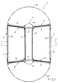
- a revolving door system is installed in a doorway of a building.
- the revolving door system 1 includes two outer walls 2, a center core 3, a ceiling member 4 and a floor member 5, which define two parallel passageways 6 and 7 having the same cross-section.
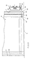
- the center core 3 and the ceiling member 4 are mounted on a steel skeleton 8, as shown in FIGURES 4, 5 and 6.
- the revolving door system 1 also includes a door supporting arrangement 9.
- the door supporting arrangement 9 includes an upper rail 10 and a lower rail 11 mounted on the skeleton 8 within the center core 3, a set of upper and lower suspension devices 13 and 14 for each door 12.
- Each of the upper suspension devices 13 supports the upper portion of its associated door 12 via an associated carrier bar 15, and each of the lower suspension devices 14 supports the lower portion of its associated door 12.
- Each carrier bar 15 is movable along a predetermined path extending through the passageways 6 and 7.
- the carrier bars 15 and the associated doors 12 are driven by a door driving arrangement 16.
- Each door 12 has a size corresponding to the vertical cross-section of the passageways 6 and 7. Plural such doors 12 are used, and the same number of carrier bars 15 are used. In the illustrated example, four doors 12 and four carrier bars 15 are employed.
- the building doorway is formed in an outer building wall 17.
- the outer walls 2 of the door system 1 are disposed in parallel with each other on opposite sides of the center core 3.
- a spacing equal to the width of the passageways 6 and 7 is disposed between the center core 3 and each of the outer walls 2.
- the outer walls 2 are connected to the building outer wall 17 at appropriate portions on their outer surfaces.
- the center core 3 includes an enclosure wall formed of two parallel, straight portions 18 having a length substantially equal to the length of the outer walls 2, and two circular arcs 19 each connecting respective one ends of the straight portions 18.
- the enclosure wall has substantially the same height as the outer walls 2.
- the ceiling member 4 is hollow and has a predetermined thickness. It is disposed to lie on top of the center core 3 and the outer walls 2 on opposite sides of the center core 3.
- the ceiling member 4 has semicircular end portions 20 (shown in double phantom lines in FIGURE 2) extending inward and outward of the building from the opposite ends of the passageways 6 and 7.
- the peripheral edges of the semicircular portions 20 substantially coincide with the path along which the outer edge of each door 12 follows when it turns.
- the floor member 5 is disposed to extend between the lower ends of the opposite sides of the center core and the lower ends of the outer walls 2, and also extend at least to the same extent as the ceiling member 4.
- the floor member 5 provides a continuous flat surface.
- the inner surfaces 2a of the outer walls 2, the outer surfaces 18a of the straight portions 18 of the center core 3, the lower surface 4a of the ceiling member 4 and the upper surface of the floor member 5 define the passageways 6 and 7 on the opposite sides of the center core 3.
- One of the passageways 6 and 7 is for entrance, and the other is for exit.
- the skeleton 8 includes two main pillars 21 disposed in the inner space of the center core 3, four corner pillars 22 at the four ends of the two outer walls 2, upper longitudinal beams 23 and 24, lower longitudinal beams 25 and 26, four upper transverse beams 27, two upper longitudinal beams 28, and reinforcing members.
- the upper and lower longitudinal beams 23-26 are disposed within the center core 3 and connect the two main pillars 21.
- the four upper transverse beams 27 are disposed within the space of the ceiling member 4. Two of the upper transverse beams 27 extend from each main pillar 21 in opposite directions and are connected to the upper ends of two of the four corner pillars 22.
- the two upper longitudinal beams 28 extend outward from the top ends of the respective ones of the two main pillars 21 into the respective semicircular end portions 20 of the ceiling member 4.
- the upper rail 10 and the lower rail 11 are secured to the skeleton 8 within the center core 3, as shown in FIGURES 4, 5 and 6.
- the upper rail 10 includes two parallel straight rail portions 10a and two semicircular end portions 10b each connecting the ends of the straight rail portions 10a on the same side.
- the lower rail 11 includes two parallel straight rail portions 11a and two semicircular end portions 11b each connecting the ends of the straight rail portions 11a on the same side.
- the upper and lower rails 10 and 11 are of the same size and shape and are vertically spaced in parallel with each other.
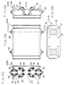
- Each of the upper and lower rails 10 and 11 is formed of a rod having a hexagonal cross-section, as shown in FIGURES 7 and 8.
- each of the upper and lower suspension devices 13 and 14 includes a solid box 29 and four wheel supports 31 disposed within the box 29.
- Each of the wheel supports 31 has three radially extending shafts angularly spaced by 120° from each other.
- One of the shafts, 32 extends vertically and is rotatably supported by bearings 34 and 35 secured to the box 29, and the other two act as axles 33 for rotatably supporting respective wheels 30 through respective bearings 36.
- Two such wheel supports 31 are disposed in the upper portion in the inner space of the box 29, and the remaining two are disposed in the lower portion of the box 29.
- the upper two wheel supports 31 and the lower two wheel supports 31 are disposed to face the other two.
- four of the wheels 30 are arranged in such a manner that their outer peripheral surfaces contact with the upper or lower rail 10 or 11 at locations in a plane perpendicular to the length of the rail, and the remaining four wheels 30 are similarly arranged in such a manner that their outer peripheral surfaces contact the upper or lower rail 10 or 11 at locations in a transverse plane different from the above-mentioned one.
- two sets of four wheels 30, i.e. eight wheels 30 are disposed in each of the upper and lower suspension devices 13 and 14 or in each box 29, and the two wheel sets are contacting the rail 10 or 11 at different locations.
- screw holes 37 are formed in the box 29 for use in securing a coupling member 39 of the carrier bar 15 or a coupling member 40 of a lower door support 42, which will be described in detail later.
- the upper and lower suspension devices 13 and 14 engage with the upper and lower rails 10 and 11, respectively.
- the carrier bar 15 is coupled to the upper suspension device 13, and the lower door support 42 is coupled to the lower suspension device 14.
- a set of one such upper suspension device 13 and one such lower suspension device 14 is used for each door 12.
- Each carrier bar 15 is formed of a horizontally extending hollow body 41 in the shape of quadratic prism.
- the carrier bar 15 extends along the lower surface 4 of the ceiling member 4, as shown in FIGURES 7 and 9C, and has a length approximately equal to the width of the door 12, a width larger than the thickness of the door 12, and a predetermined height.
- the carrier bar 15 has a free end located near the outer wall 2.
- the carrier bar 15 extends into the center core 3.
- the above-mentioned coupling member 39 coupled to the associated upper suspension device 13 is disposed at the end of the carrier bar 15 located in the center core 3.
- the lower door support 42 is a member supporting the lower end of the center core side of the door 12, as shown in FIGURE 8, and has the above-mentioned coupling member 40 vertically facing the coupling member 39.
- the lower door support 42 is coupled to the lower suspension device 14 via the coupling member 40.
- the carrier bar 15 and the lower door support 42 are interconnected by a vertical support 38.
- the vertical support 38 has a length corresponding to the vertical dimension of the door 12 and is formed of a member having a shallow U-shaped cross-section, as shown in FIGURE 9C.
- the vertical support 38 is provided with an outer cover 43 so that it appears to extend in the vicinity of and along the outer surface of the center core 3, to have a concave surface facing the center core 3, and to have a flat shape having a width slightly larger than the thickness of the door 12.
- a rubber-like member 90 is attached to the both side edges of the outer cover 43.
- the coupling member 39 is directly coupled to the upper suspension device 13, while the lower coupling member 40 is coupled to the lower suspension device 14 through rubber bushes 44 which can contract and expand and act as an error absorbing device. (Such error absorbing device may be disposed between the upper suspension device 13 and the coupling member 39.)
- the upper and lower coupling members 39 and 40 extend into the center core 3 through horizontal peripheral openings 45 and 46, respectively, in the wall of the center core 3.
- the openings 45 and 46 extend entirely around the center core 3.
- the rubber bushes 44 absorb errors, such as errors in parallelism between the upper and lower rails 10 and 11 and errors which could occur in assembling the upper and lower suspension devices 13 and 14, so that the door 12 and the carrier bar 15 can move smoothly on the rails.
- each of the upper and lower suspension devices 13 and 14 is arranged to clamp the rail 10 or 11 by the eight wheels 30.
- the spacing between the upper and lower rails 10 and 11 may vary more or less from location to location along their length, but such variations can be absorbed by the elastic deformation of the rubber bushes 44 to thereby prevent deformation and damage of other portions, and large increase of moving resistance of the door 12.
- Upper and lower pivots 47 and 48 are provided to extend upward and downward from the top and bottom ends of the door 12 on the center core side.
- the center axes of the pivots 47 and 48 are vertically aligned.
- the upper pivot 47 extends into the inner space of the carrier bar 15 and has its upper end portion rotatably supported by a bearing 49.
- a sprocket 60 of a later-mentioned automatic door closing arrangement 57 is secured to the upper end of the pivot 47.
- the lower pivot 48 extends into the lower door support 42 and is rotatably supported by a bearing 50.
- the pivot 48 may be provided on the lower door support 42 with the bearing 50 disposed on the door 12.
- the door 12 is rotatable about the pivots 47 and 48.
- an electromagnetic door detention arrangement or electromagnetic locking arrangement 51 including a solenoid 52 and an iron piece member 53 is disposed in an area including the distal end portions of the hollow body 41 and the door 12 remote from the center core 3.
- the solenoid 52 is disposed within the hollow body 41 of the carrier bar 15, and the iron piece member 53 is secured to the upper portion of the door 12 at a location corresponding to the location of the solenoid 52 in the hollow body 41.
- the solenoid 52 operates to attract the iron piece member 53 to thereby detain the door 12 in place with respect to the carrier bar 15.
- sensors 54 for sensing a human or an article present in front of the door 12 are disposed.
- the sensors 54 when sensing a human or an article in front of the door 12, generate an object representative signal, which may be used to stop the door system, for example. If necessary, similar sensors may be provided in the lower portion of the vertical support 38.
- a short linking member 55 protrudes upward from the top of the coupling member 39 of the carrier bar 15 beyond the upper edge of the center core 3.
- a pulling bar 56 formed of an upward opening, generally U-shaped member is secured to the top end of the linking member 55, so that the carrier bar 15 and the pulling bar 56 are coupled to each other via the coupling member 56.
- the pulling bar 56 extends within the ceiling member 4 in parallel with the carrier bar 15, from the linking member 55 to a position slightly outward of the midpoint of the width of the door 12.
- the automatic door closing arrangement 57, a connecting rod 58, and a signal transmitting slider 59 are disposed on the pulling bar 56, as shown in FIGURES 7, 9A, 9B and 9C.
- the door 12 can be swung open about the pivots 47 and 48 in either direction by external force exerted to it.
- the rotation of the door 12 is transmitted through the sprocket 60, a chain 61 engaging with the sprocket 60, a sprocket 62 engaged with by the chain 61, a shaft 63 to which the sprocket 62 is secured, one of sprockets 64 and 65 secured to the shaft 63, and associated one of chains 66 and 67 engaging with the sprockets 64 and 65, respectively, to associated one of sprockets 68 and 69 on main bodies 70 and 70a.
- the rotation of the door 12 transmitted to the sprocket 68 or 69 is stored in a spring (not shown) disposed within the main body 70 or 70a.
- a spring (not shown) disposed within the main body 70 or 70a.
- the spring releases the energy stored in it so that the door 12 is returned to its original position.
- the two sets of sprocket and chain arrangements namely, the sprockets 64 and 65, the chains 66 and 67, and the sprockets 68 and 69, are used to return the door 12 to its original position regardless of the direction of the swing of the door 12.
- the sprocket 60, the chain 61, the sprocket 62, the shaft 63, the sprocket 64, the chain 66, the sprocket 68 and the associated spring in the main body 70 operate, and, if the door 12 is swung open in the opposite direction, the sprocket 60, the chain 61, the sprocket 62, the shaft 63, the sprocket 65, the chain 67, the sprocket 69 and the associated spring in the main body 70a operate.
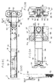
- the door driving arrangement 16 includes, as shown in FIGURES 4, 5 and 6, a plurality of sprockets 72 rotatably supported by associated sprocket supports 71 which, in turn, are secured to appropriate locations of the skeleton 8 within the ceiling member 4, a driving chain 75 disposed to engage with the respective sprockets 72, and a rotation driver 76 mounted on a predetermined one, 72A, of the sprockets 72.
- the driving chain 75 moves along straight paths 73 and along generally arcuate paths 74, as shown in FIGURE 5.
- the driver 76 includes an electric motor 77 mounted within the center core 3, a sprocket 79 having a smaller diameter secured to a rotation shaft 78 of the motor 77, a sprocket 80 having a larger diameter secured to the shaft of the predetermined sprocket 72A, and a driving force transmitting chain 81 wrapped around the sprockets 79 and 80. As the motor 77 rotates, the driving chain 75 is driven at a reduced speed.
- the connecting rods 58 equal in number to the carrier bars 15, four in the illustrated example, are secured to the driving chain 75 at predetermined intervals.
- the connecting rod 58 has its one end coupled to the pulling bar 56 in such a manner as to be rotatable about a vertically extending pivot 82 secured to the pulling bar 56.
- the connecting rod 58 is connected to the pulling bar 56 at a location which is above the midpoint of the width of the door 12 when the door 12 is electromagnetically detained in place with respect to the carrier bar 15.
- the other end of the connecting rod 58 is connected to the driving chain 75 of the door driving arrangement 16.
- the four connecting rods 58 for the respective ones of the four doors 12 are connected to the driving chain 75 at locations spaced at equal intervals.
- the doors 12 supported by the respective carrier bars 15 can assume respective positions shown in FIGURE 2 where they close the opposite ends of the passageways 6 and 7 during the course of the movement described later.
- a control unit (not shown) controls the revolving door system 1 with the above-described door supporting arrangement 9 in such a manner that the respective doors 12 may assume the respective positions shown in FIGURE 2 where the opposite ends of each of the passageways 6 and 7 are closed, when no one is entering or exiting through the passageway 6 or 7, and that when a human is approaching the passageway 6 or 7, the doors 12 move in the predetermined direction indicated by arrows so that he or she can enter or exit from the building.
- the revolving door system assumes again the position shown in FIGURE 2 and remains therein.
- the doors 12 are moved by the operation of the door driving arrangement 16.
- the driving chain 75 travels in a predetermined direction at a predetermined speed, which drives the connecting rods 58 and, hence, the pulling bars 56 .
- the carrier bars 15 connected to the pulling bars 56, the linking member 55, the upper suspension device 13, the lower suspension device 14, the lower supports 42, the vertical supports 38 etc. move, together with the associated doors 12, along the upper and lower rails 10 and 11.
- each door 12 is detained in position by the associated electromagnetic door detention arrangements 51.
- the upper and lower pivots 47 and 48 of each door 12 are rotatably supported by the bearings 49 and 50 disposed on the associated carrier bar 15 and lower door support 42.
- Some detaining force is applied to the upper pivot 47 by the automatic door closing arrangement 57 to detain the door 12 in place.
- the electromagnetic door detention arrangement 51 adds a locking force to electromagnetically couple the carrier bar 15 to the door 12.
- the carrier bar 15 is coupled to the upper suspension device 13 and to the lower suspension device 14 via the vertical support 38.
- the vertical supports 38 provide better holding of the doors 12, but they may be eliminated depending on the site where the revolving door system is installed, the weight of the doors 12, the strength of each of the parts of the door supporting arrangement.
- the electromagnetic door detention arrangement 51 of a particular one of the doors 12 disabled, that door can be rotated open against the detaining force provided by the automatic door closing arrangement 57 about the upper and lower pivots 47 and 48. Accordingly, when the revolving door system 1 stops for some reason, and, therefore, a person is confined in a space between the two doors 12, the electromagnetic door detention arrangement 51 of either or both of the two doors 12 is disabled, which permits either or both doors to be opened manually.
- the manually opened door 12 is automatically closed by the automatic door closing arrangement 57 when the manual force exerted to the door 12 is removed. Then, the operation of the revolving door system 1 can be resumed upon removal of the cause that stopped the system 1.
- Each of the carrier bars 15 is hollow and can house its associated components, such as the solenoid 52 of the electromagnetic door detention arrangement 51, the sensor 54, the bearing 49, the sprocket 60 and the chain 61 of the automatic door closing arrangement 57, whereby the appearance of each door 12 is not marred.
Landscapes
- Engineering & Computer Science (AREA)
- Civil Engineering (AREA)
- Structural Engineering (AREA)
- Power-Operated Mechanisms For Wings (AREA)
- Extensible Doors And Revolving Doors (AREA)
Applications Claiming Priority (2)
| Application Number | Priority Date | Filing Date | Title |
|---|---|---|---|
| JP31300199A JP3323167B2 (ja) | 1999-11-02 | 1999-11-02 | 回転扉の扉支持機構 |
| JP31300199 | 1999-11-02 |
Publications (2)
| Publication Number | Publication Date |
|---|---|
| EP1098062A2 true EP1098062A2 (de) | 2001-05-09 |
| EP1098062A3 EP1098062A3 (de) | 2004-07-21 |
Family
ID=18036047
Family Applications (1)
| Application Number | Title | Priority Date | Filing Date |
|---|---|---|---|
| EP00122706A Withdrawn EP1098062A3 (de) | 1999-11-02 | 2000-10-18 | Karusselltürsystem |
Country Status (5)
| Country | Link |
|---|---|
| US (1) | US6493991B1 (de) |
| EP (1) | EP1098062A3 (de) |
| JP (1) | JP3323167B2 (de) |
| KR (1) | KR100379353B1 (de) |
| CN (1) | CN1123672C (de) |
Families Citing this family (5)
| Publication number | Priority date | Publication date | Assignee | Title |
|---|---|---|---|---|
| NL1014503C2 (nl) * | 2000-02-25 | 2001-08-28 | Boon Edam Bv | Draaideur. |
| US7707951B1 (en) * | 2000-09-21 | 2010-05-04 | Romeo Prasad | System for preventing crime in high traffic areas and sites using low voltage power |
| US7900398B2 (en) | 2006-11-14 | 2011-03-08 | Overhead Door Corporation | Security door system |
| CN105569517B (zh) * | 2015-08-07 | 2017-12-05 | 重庆天春科技有限公司 | 自动旋转门 |
| CN117739088B (zh) * | 2024-02-18 | 2024-04-30 | 四川腾盾科技有限公司 | 一种无人机尾舱门传动系统及无人机尾舱门结构 |
Citations (2)
| Publication number | Priority date | Publication date | Assignee | Title |
|---|---|---|---|---|
| NL7902203A (nl) | 1979-03-21 | 1980-09-23 | Jacob Robert Alfred Huber | Draaideur. |
| JPS56481B2 (de) | 1975-05-28 | 1981-01-08 |
Family Cites Families (11)
| Publication number | Priority date | Publication date | Assignee | Title |
|---|---|---|---|---|
| US619674A (en) * | 1899-02-14 | Storm-door | ||
| US732982A (en) * | 1903-04-06 | 1903-07-07 | Julius Wendler | Apparatus for closing entrances. |
| US3353298A (en) * | 1964-06-17 | 1967-11-21 | Stephen J Pfender | Movable door structure |
| JPS5320049A (en) * | 1976-08-06 | 1978-02-23 | Mitsubishi Electric Corp | Electromagnetic device fro use in electromagnetic connector device and process for making the same |
| US4341165A (en) * | 1980-05-29 | 1982-07-27 | Calandritti R | Security system including a revolving door |
| US4586441A (en) * | 1982-06-08 | 1986-05-06 | Related Energy & Security Systems, Inc. | Security system for selectively allowing passage from a non-secure region to a secure region |
| JPS60177277U (ja) | 1984-05-07 | 1985-11-25 | ワイケイケイ株式会社 | 戸の支持装置 |
| DE3934662A1 (de) * | 1989-10-18 | 1991-04-25 | Gallenschuetz E Metallbau | Sicherheitsschaltung fuer elektromotorisch angetriebene und elektrisch brems- oder arretierbare schwungmassen oder maschinenteile |
| DE3940176C1 (de) * | 1989-12-05 | 1991-05-16 | Gallenschuetz Metallbau Gmbh, 7580 Buehl, De | |
| JP3171699B2 (ja) | 1992-09-30 | 2001-05-28 | 株式会社ナブコ | 自動回転ドア |
| DE19651948C1 (de) * | 1996-12-16 | 1998-04-16 | Dorma Land Brandenburg Gmbh | Karusselltür |
-
1999
- 1999-11-02 JP JP31300199A patent/JP3323167B2/ja not_active Expired - Fee Related
-
2000
- 2000-10-12 US US09/689,559 patent/US6493991B1/en not_active Expired - Fee Related
- 2000-10-18 EP EP00122706A patent/EP1098062A3/de not_active Withdrawn
- 2000-10-26 KR KR10-2000-0063090A patent/KR100379353B1/ko not_active Expired - Fee Related
- 2000-11-02 CN CN00133725A patent/CN1123672C/zh not_active Expired - Fee Related
Patent Citations (2)
| Publication number | Priority date | Publication date | Assignee | Title |
|---|---|---|---|---|
| JPS56481B2 (de) | 1975-05-28 | 1981-01-08 | ||
| NL7902203A (nl) | 1979-03-21 | 1980-09-23 | Jacob Robert Alfred Huber | Draaideur. |
Also Published As
| Publication number | Publication date |
|---|---|
| US6493991B1 (en) | 2002-12-17 |
| CN1295174A (zh) | 2001-05-16 |
| JP2001132311A (ja) | 2001-05-15 |
| KR100379353B1 (ko) | 2003-04-08 |
| JP3323167B2 (ja) | 2002-09-09 |
| EP1098062A3 (de) | 2004-07-21 |
| KR20010051252A (ko) | 2001-06-25 |
| CN1123672C (zh) | 2003-10-08 |
Similar Documents
| Publication | Publication Date | Title |
|---|---|---|
| JPH02183080A (ja) | 扉 | |
| US6493991B1 (en) | Revolving door system | |
| JP2659488B2 (ja) | 引戸装置 | |
| US4897959A (en) | Jail cell lock mechanism | |
| WO2005052298A1 (en) | Security entrance with two doors | |
| JP3452261B2 (ja) | シャッターパネルの落下防止装置 | |
| JPH06221054A (ja) | 自動開閉引戸の開閉装置 | |
| KR102861892B1 (ko) | 도어 자동개폐장치 | |
| JP2557576Y2 (ja) | 超重量扉の開閉構造 | |
| JP2992614B2 (ja) | 自動回転スライドドア装置 | |
| KR200372381Y1 (ko) | 자동도어의 개폐 장치 | |
| JPH11229728A (ja) | シャッター装置 | |
| JPS593621B2 (ja) | エレベ−タ用折り戸装置 | |
| JPH06173559A (ja) | 門扉駆動ユニット | |
| JPH07166773A (ja) | 航空機格納庫の開閉扉 | |
| JP2000136082A (ja) | エレベーターのカゴドア | |
| JPH0323511Y2 (de) | ||
| JP3726324B2 (ja) | シャッター | |
| JP3169854B2 (ja) | 回動体の回動装置 | |
| JPH061686U (ja) | 航空機格納庫の大扉 | |
| JP4331302B2 (ja) | エレベータ | |
| JPH0344916Y2 (de) | ||
| JPH0616079Y2 (ja) | シヤツタ−開閉駆動装置 | |
| JPH043112Y2 (de) | ||
| JPH03102090A (ja) | エレベータドア装置 |
Legal Events
| Date | Code | Title | Description |
|---|---|---|---|
| PUAI | Public reference made under article 153(3) epc to a published international application that has entered the european phase |
Free format text: ORIGINAL CODE: 0009012 |
|
| AK | Designated contracting states |
Kind code of ref document: A2 Designated state(s): AT BE CH CY DE DK ES FI FR GB GR IE IT LI LU MC NL PT SE |
|
| AX | Request for extension of the european patent |
Free format text: AL;LT;LV;MK;RO;SI |
|
| PUAL | Search report despatched |
Free format text: ORIGINAL CODE: 0009013 |
|
| AK | Designated contracting states |
Kind code of ref document: A3 Designated state(s): AT BE CH CY DE DK ES FI FR GB GR IE IT LI LU MC NL PT SE |
|
| AX | Request for extension of the european patent |
Extension state: AL LT LV MK RO SI |
|
| RIC1 | Information provided on ipc code assigned before grant |
Ipc: 7E 06B 3/90 B Ipc: 7E 05F 15/10 B Ipc: 7E 05D 15/02 A |
|
| AKX | Designation fees paid | ||
| REG | Reference to a national code |
Ref country code: DE Ref legal event code: 8566 |
|
| STAA | Information on the status of an ep patent application or granted ep patent |
Free format text: STATUS: THE APPLICATION IS DEEMED TO BE WITHDRAWN |
|
| 18D | Application deemed to be withdrawn |
Effective date: 20050122 |