EP1101877A1 - Materiau d'isolation et son procede de fabrication - Google Patents
Materiau d'isolation et son procede de fabrication Download PDFInfo
- Publication number
- EP1101877A1 EP1101877A1 EP00931645A EP00931645A EP1101877A1 EP 1101877 A1 EP1101877 A1 EP 1101877A1 EP 00931645 A EP00931645 A EP 00931645A EP 00931645 A EP00931645 A EP 00931645A EP 1101877 A1 EP1101877 A1 EP 1101877A1
- Authority
- EP
- European Patent Office
- Prior art keywords
- mat
- surface film
- film
- thermal insulating
- rear end
- Prior art date
- Legal status (The legal status is an assumption and is not a legal conclusion. Google has not performed a legal analysis and makes no representation as to the accuracy of the status listed.)
- Granted
Links
Images


Classifications
-
- F—MECHANICAL ENGINEERING; LIGHTING; HEATING; WEAPONS; BLASTING
- F16—ENGINEERING ELEMENTS AND UNITS; GENERAL MEASURES FOR PRODUCING AND MAINTAINING EFFECTIVE FUNCTIONING OF MACHINES OR INSTALLATIONS; THERMAL INSULATION IN GENERAL
- F16L—PIPES; JOINTS OR FITTINGS FOR PIPES; SUPPORTS FOR PIPES, CABLES OR PROTECTIVE TUBING; MEANS FOR THERMAL INSULATION IN GENERAL
- F16L59/00—Thermal insulation in general
- F16L59/04—Arrangements using dry fillers, e.g. using slag wool
-
- E—FIXED CONSTRUCTIONS
- E04—BUILDING
- E04B—GENERAL BUILDING CONSTRUCTIONS; WALLS, e.g. PARTITIONS; ROOFS; FLOORS; CEILINGS; INSULATION OR OTHER PROTECTION OF BUILDINGS
- E04B1/00—Constructions in general; Structures which are not restricted either to walls, e.g. partitions, or floors or ceilings or roofs
- E04B1/62—Insulation or other protection; Elements or use of specified material therefor
- E04B1/74—Heat, sound or noise insulation, absorption, or reflection; Other building methods affording favourable thermal or acoustical conditions, e.g. accumulating of heat within walls
- E04B1/76—Heat, sound or noise insulation, absorption, or reflection; Other building methods affording favourable thermal or acoustical conditions, e.g. accumulating of heat within walls specifically with respect to heat only
- E04B1/7654—Heat, sound or noise insulation, absorption, or reflection; Other building methods affording favourable thermal or acoustical conditions, e.g. accumulating of heat within walls specifically with respect to heat only comprising an insulating layer, disposed between two longitudinal supporting elements, e.g. to insulate ceilings
- E04B1/7658—Heat, sound or noise insulation, absorption, or reflection; Other building methods affording favourable thermal or acoustical conditions, e.g. accumulating of heat within walls specifically with respect to heat only comprising an insulating layer, disposed between two longitudinal supporting elements, e.g. to insulate ceilings comprising fiber insulation, e.g. as panels or loose filled fibres
- E04B1/7662—Heat, sound or noise insulation, absorption, or reflection; Other building methods affording favourable thermal or acoustical conditions, e.g. accumulating of heat within walls specifically with respect to heat only comprising an insulating layer, disposed between two longitudinal supporting elements, e.g. to insulate ceilings comprising fiber insulation, e.g. as panels or loose filled fibres comprising fiber blankets or batts
- E04B1/7666—Connection of blankets or batts to the longitudinal supporting elements
- E04B1/767—Blankets or batts with connecting flanges
-
- E—FIXED CONSTRUCTIONS
- E04—BUILDING
- E04B—GENERAL BUILDING CONSTRUCTIONS; WALLS, e.g. PARTITIONS; ROOFS; FLOORS; CEILINGS; INSULATION OR OTHER PROTECTION OF BUILDINGS
- E04B1/00—Constructions in general; Structures which are not restricted either to walls, e.g. partitions, or floors or ceilings or roofs
- E04B1/62—Insulation or other protection; Elements or use of specified material therefor
- E04B1/74—Heat, sound or noise insulation, absorption, or reflection; Other building methods affording favourable thermal or acoustical conditions, e.g. accumulating of heat within walls
- E04B1/76—Heat, sound or noise insulation, absorption, or reflection; Other building methods affording favourable thermal or acoustical conditions, e.g. accumulating of heat within walls specifically with respect to heat only
- E04B1/78—Heat insulating elements
-
- F—MECHANICAL ENGINEERING; LIGHTING; HEATING; WEAPONS; BLASTING
- F16—ENGINEERING ELEMENTS AND UNITS; GENERAL MEASURES FOR PRODUCING AND MAINTAINING EFFECTIVE FUNCTIONING OF MACHINES OR INSTALLATIONS; THERMAL INSULATION IN GENERAL
- F16L—PIPES; JOINTS OR FITTINGS FOR PIPES; SUPPORTS FOR PIPES, CABLES OR PROTECTIVE TUBING; MEANS FOR THERMAL INSULATION IN GENERAL
- F16L59/00—Thermal insulation in general
- F16L59/02—Shape or form of insulating materials, with or without coverings integral with the insulating materials
- F16L59/026—Mattresses, mats, blankets or the like
-
- Y—GENERAL TAGGING OF NEW TECHNOLOGICAL DEVELOPMENTS; GENERAL TAGGING OF CROSS-SECTIONAL TECHNOLOGIES SPANNING OVER SEVERAL SECTIONS OF THE IPC; TECHNICAL SUBJECTS COVERED BY FORMER USPC CROSS-REFERENCE ART COLLECTIONS [XRACs] AND DIGESTS
- Y10—TECHNICAL SUBJECTS COVERED BY FORMER USPC
- Y10T—TECHNICAL SUBJECTS COVERED BY FORMER US CLASSIFICATION
- Y10T428/00—Stock material or miscellaneous articles
- Y10T428/249921—Web or sheet containing structurally defined element or component
- Y10T428/249924—Noninterengaged fiber-containing paper-free web or sheet which is not of specified porosity
- Y10T428/24994—Fiber embedded in or on the surface of a polymeric matrix
- Y10T428/249941—Fiber is on the surface of a polymeric matrix having no embedded portion
-
- Y—GENERAL TAGGING OF NEW TECHNOLOGICAL DEVELOPMENTS; GENERAL TAGGING OF CROSS-SECTIONAL TECHNOLOGIES SPANNING OVER SEVERAL SECTIONS OF THE IPC; TECHNICAL SUBJECTS COVERED BY FORMER USPC CROSS-REFERENCE ART COLLECTIONS [XRACs] AND DIGESTS
- Y10—TECHNICAL SUBJECTS COVERED BY FORMER USPC
- Y10T—TECHNICAL SUBJECTS COVERED BY FORMER US CLASSIFICATION
- Y10T428/00—Stock material or miscellaneous articles
- Y10T428/249921—Web or sheet containing structurally defined element or component
- Y10T428/249924—Noninterengaged fiber-containing paper-free web or sheet which is not of specified porosity
- Y10T428/24994—Fiber embedded in or on the surface of a polymeric matrix
- Y10T428/24995—Two or more layers
- Y10T428/249952—At least one thermosetting synthetic polymeric material layer
Definitions
- This invention relates to a thermal insulating article prepared by covering a mat made of inorganic fibers such as glass wool or rock wool, with a film coat along an entire surface including upper and lower surfaces, lateral sides and front and rear sides, and also relates to a method of manufacturing such a thermal insulating article.
- thermal insulating articles made of inorganic fibers such as those of glass wool or rock wool have a stimulating itchy effect specific to such fibers, so that they are normally covered with a film coat in order to eliminate such a stimulating effect and also prevent the degradation of the thermal insulating article due to dew condensation.
- Japanese Patent Laid-Open Nos. 53-39067 and 6-79849 and Japanese Utility Model Laid Open No. 52-162710 disclose techniques for covering a mat of inorganic fibers with a film coat along the entire surface including the upper and lower surfaces, the lateral sides and the front and rear sides. Coated mats according to the above described patent are normally compressed for packaging for the purpose of improving the efficiency of packing and packaging.
- the film coat is perforated to discharge or release air in the inside, and/or the end lugs binding the opposite edges of the film coat is made apt to aerate in order to quickly discharge air from the inside of the mat, to prevent the film coat from being torn by bursting air at the time of compressing and packaging, and to make air quickly flow into the inside to expand the mat after unpacking.
- Japanese Patent Laid-Open No. 53-96076 discloses means for manufacturing a thermal insulating article having a predetermined length, wherein mats of the above described type having an appropriate thickness and a predetermined length are constantly moved on a line at regular intervals, while covering them by a film from above and below in a continuous operation, and heating and fusing the upper film and the lower film for bonding along the lateral sides and also at the front and rear ends of each mat at appropriate respective positions on the line. Then, the fused areas of the film are cut along the center line thereof to produce thermal insulating articles having the predetermined length.
- mats typically made of glass wool and thermoplastic resin film are fed simultaneously, and the film is partly heated and fused for bonding along the front and rear edges of each mat as viewed in the feeding direction. Subsequently the film is cut along the thermally fused and bonded areas, and partly torn apart along the feeding direction in the areas that are not thermally fused, so that consequently the film show a predetermined length for each mat. Then, the pieces of film cut apart are used to cover the lateral sides and the front and rear sides of the mat to complete the process of forming a thermal insulating article.
- FIG. 3 of the accompanying drawings schematically illustrates the mat and the film covering the upper and lower surfaces of the mat. If the length W of the end lugs is too long, it would be pinched by and/or entangled by the packaging machine in the compression/packaging process, to interfere with and stop the operation of the machine, and to reduce the efficiency of the operation. Additionally, the end lugs would extend to the outside of the installation frame for containing the thermal insulating article, so that the extended part of the film may have to be cut, to increase the work load and prolong the installing operation.
- the compressed and packaged thermal insulating article is used for thermal insulation and sound absorption, it is normally compressed to a size equal to 1/2 to 1/10 of the size provided in JIS (Japanese Industrial Standards) for packaging. Then, the compressed thermal insulating article has to be made to restore the size conforming to JIS.
- JIS Japanese Industrial Standards
- the sealing length L 1 is reduced to dissolve the first problem, the upper film and the lower film would be peeled off from each other along bonded areas due to the resilient force of the compressed mat.
- sealing length L 1 is reduced by compressing the mat between the front and rear ends, to make it smaller than the size defined by JIS before covering it with film, the film tension would be raised to press the mat, so that the mat would not restore the original size to meet the dimensional requirement of JIS.
- thermal insulating article that is completely covered by a film coat along the entire surface thereof to meet the requirements of the applicable standards in terms of structure, strength and so on and still can be manufactured and installed efficiently at low cost.
- Another object of the present invention is to provide a method of manufacturing such thermal insulating articles in a continuous way.
- thermoinsulating article comprising a rectangularly parallelepipedic mat of an aggregate of inorganic fibers, a synthetic resin upper surface film and a synthetic resin lower surface film;
- a method of manufacturing a thermal insulating article comprising a mat of inorganic fibers, an upper surface film bonded to an upper surface of the mat and a lower surface film bonded to a lower surface of the mat, said upper surface film and said lower surface film being bonded to each other along edge lugs and end lugs of the thermal insulating article; said method comprising steps of:
- FIGS. 1 through 4 schematically illustrate a preferred embodiment of a thermal insulating article according to the invention.
- the thermal insulating article 1 illustrated in Fig. 1 comprises a rectangularly parallelepipedic mat 2 which is made of an aggregate of inorganic fibers and has thermal insulative properties, an upper surface film 3 made of synthetic resin covering an upper surface of the mat 2 as film coat, and a lower surface film 4 made of synthetic covering a lower surface of the mat 2 as film coat.
- the thermal insulating article 1 has lateral surfaces 5, each of which is a longitudinal edge surface, a front end surface 9 that is an end surface, a rear end surface 10 that is another end surface, edge lugs 6, each of which extends laterally outwardly from a lower edge of each of the lateral surfaces 5, and end lugs 11, each of which extends forwardly and backwardly from each of lower edges of the front and rear end surfaces 9 and 10.
- Said upper surface film 3 and said lower surface film 4 are bonded together along the edge lugs 6 and the end lugs 11 for sealing to produce a complete thermal insulating article 1.
- Said upper surface film 3 is bent so as to extend along the lateral surface 5 to the lower surface of the thermal insulating article 1, and is bonded to the lower surface film 4 along the edge lug 6.
- the upper surface film 3 and the mat 2 are pushed and compressed downwardly to the lower surface film 4 in a manner as described hereinafter, and the upper surface film 3 is bonded to the lower surface film 4 along the end lug 11.
- the mat 2 is entirely sealed by the upper surface film 3 and the lower surface film 4 along the entire periphery thereof, so as to prevent fine fibers scattering to prevent itchy.
- the upper surface film 3 is provided in each of the lateral surfaces 5 with air holes 7 intermittently arranged in a plurality of rows running along the longitudinal direction of the thermal insulating article 1, and is also provided in each of end surfaces 9 and 10 with air holes 7.
- air holes 7 are provided, air contained in the mat 2 covered by the films 3, 4 can easily be discharged through the air holes 7, when the mat 2 is compressed and packaged.
- said upper surface film 3 and said lower surface film 4 are bonded to each other at a plurality of bonding areas 8A.
- Said plurality of bonding areas 8A are arranged along the longitudinal direction.
- said upper surface film 3 and said lower surface film 4 are bonded to each other at a plurality of bonding areas 8B.
- Each of said bonding areas 8A, 8B may be in the form of linear slits or spots.
- FIG. 2 is a schematic illustration showing a relationship between a length L of each mat and a sealing length L 1 in the continuous manufacturing process of the mats illustrated in Fig. 1.
- Said sealing length L 1 is the sum of a length of the upper surface film 3 necessary for covering the front and the rear end surfaces 9, 10 of the mat 2, and a length of the upper surface film 3 between the rear end surface 10 of a mat and the front end surface 9 of the adjacent mat. Between the rear end surface 10 of a mat and the front end surface of the adjacent mat, the upper surface film 3 and the lower surface film 4 are bonded to each other to form a pair of end lugs 11.
- the length L 1 is defined or determined in a manner as described below.
- the mat 2 has a central section having a thickness C, a front end section 9A and a rear end section 10A, as illustrated in Fig. 3. When the thermal insulating article 1 is packaged, it is compressed and hence the mat 2 is also compressed.
- the compressed dimension H (a vertical distance between the upper surface of the mat at the central section and the top of each of the end surfaces 9, 10) is so determined as to allow the compressed mat 2 to maintain a predetermined thickness "a" at the ends 9 and 10 when the thermal insulating article is compressed.
- the length L 1 is determined or obtained from the compressed dimension H.
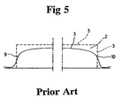
- a thermal insulating article is compressed by merely pressing the upper film 3 downwardly toward the lower film 4 along the end surfaces 9, 10 from the original position as indicated by broken lines in FIG. 5.
- the prior art lacks a consideration or concept of maintaining thickness "a" at the ends 9, 10 of the mat 2 when the thermal insulating article is compressed.
- a mat having a thickness greater than the predetermined thickness by 10 to 30% is compressed as shown in FIG. 5 schematically illustrating how a prior art mat is compressed, and the upper and lower films are cut while the mat is held in the compressed state.
- the thermal insulating article is made to show a bowed longitudinal cross section as shown in FIG. 5 so that the central section cannot maintain a uniform thickness C.
- the mat is compressed at the front and the rear ends 9A, 10A by height H to secure a predetermined thickness "a" for the front and the rear ends 9, 10 as will be discussed hereinafter, and then the upper surface film 3 and the lower surface film 4 are bonded together. Therefore, the central section of the mat 2 is not subjected to any excessive tensile force, so that the problem of the prior art as pointed out above does not arise.
- air holes may be formed on the upper surface film 3 and/or the lower surface film 4 of the thermal insulating article 1 in order to allow the thermal insulating article to permeate moisture therethrough.
- the bonded areas of the end lugs 11 of the thermal insulating article 1 may be realized in the form of a single or plurality of rows of continuous strips, discontinuous short strips or round spots. Still additionally, the intervals separating the discontinuous bonded areas may be used for air holes.
- the upper and lower surface films 3, 4 and the mat 2 may be bonded by using the heat sensitive bonding ability of the films or by using an appropriate adhesive of the hot melt type or some other type.
- the thermal insulating article according to the invention can operate as a sound absorbing thermal insulating article.
- FIGS. 6 and 7 schematically illustrate an embodiment of the method of manufacturing the thermal insulating article according to invention.
- FIG. 6 shows the manufacturing process using a manufacturing apparatus 100.
- the method of manufacturing the thermal insulating article comprises steps of (1) molding a continuous source mat and drying it, (2) cutting the continuous mat to a predetermined length, (3) intermittently feeding unit mats thus obtained, (4) bonding the upper surface film to the upper surface of each unit mat and bonding the lower surface film to the lower surface of each unit mat, (5) bonding the upper surface film and the lower surface film along the edge lugs thereof, (6) intermittently feeding unit mats thus obtained, (7) regulating a sag caused by time lag between the above described mat cutting/transferring step and the above described step for bonding and cutting films while suspending the supply of mats, (8) feeding the mat to a sealing machine, (9) stopping the mat when a center position of the interval of adjacent mats is aligned to a center of the sealing machine, (10) compressing the rear end of a mat and the front end
- a continuous source mat 200 is molded and dried to show a predetermined density and a predetermined thickness by means of a drying machine 12, and then transferred continuously by means of a conveyor 14. Thereafter, the continuous mat 200 is cut to a predetermined length by means of a cutting machine 13 to produce unit mats 2. Each unit mat 2 is then transferred to a stopper 15. An interval of adjacent feeding mats 2 is regulated by the switching time of the stopper 15, so that unit mats are fed intermittently after passing through the stopper 15.
- An upper surface film 3 and a lower surface film 4 are drawn out respectively from an upper film feeder 18 and a lower film feeder 19 at a rate coordinated to the speed of transferring mats 2.
- adhesive is applied to a lower surface of the upper surface film 3 and an upper surface of the lower surface film 4 drawn out respectively from the film feeders 18, 19 by means of a sprayer 16 for the upper surface film 3 and a sprayer 17 for the lower surface film 4 disposed respective to the films 3, 4.
- the upper surface film 3 covers the upper surface of the mat 2 and is bonded thereto, while the lower surface film 4 is covers the lower surface of the mat 2 and is bonded thereto. Since mats 2 are supplied intermittently, a mat and the adjacent mat are separated by length L 1 , and are bonded to the upper surface film 3 and the lower surface film 4.
- the mat 2 bonded with the films 3, 4 is then brought to an edge lugs bonding apparatus 20, where the upper surface film 3 and the lower surface film 4 are bonded together along the edge lugs 6 at a plurality of bonding areas 8A.
- the front end surface 9A of a mat 2 and the rear end surface 10B of the adjacent mat are covered by the films 3, 4 by means of a sealing machine 22, which will be described hereinafter (FIG. 7).
- the sealing machine 22 covers the both end surfaces 9A and 10B with the films 3, 4, compresses the front end 90A of a mat 2 and the rear end 100B of the adjacent mat from above toward the bottom, and bonds and cuts the films 3, 4 between said front end surface 9A and said rear end surface 10B.
- the mat 2 is also compressed, as will be described hereinafter.
- mats are intermittently transferred by means of an intermittent conveyor 32.
- a sag regulating section 21 is arranged, so that the conveyor 14 can safely or smoothly feed mats corresponds to the difference or discrepancy of the feeding speeds.
- the present invention supplies mats intermittently by means of the conveyor 32, and does not move the sealing machine 22.
- the sag that arises in the mat 2 with the films 3, 4 due to the stop of the transfer is absorbed and eliminated by the sag absorbing/regulating section 21.
- FIG. 7 is a schematic cross sectional view of the sealing machine 22, illustrating its configuration.
- a position sensor (not shown) of the sealing machine 22 detects a position of the mat 2 corresponding to 1/2L 1 , and when the position of the mat 2 corresponding to 1/2L 1 is aligned with the central position of the sealing machine 22, the transfer of the mat 2 is suspended or stopped.
- the sealing machine 22 has an upper cylinder 24, a lower cylinder 28 and a pair of press cylinders 27.
- the upper cylinder 24 is arranged at a central position C 1 -C 1 where the continuous end lugs 11A, 11B between two adjacent mats 2A, 2B.
- the upper cylinder 24 is provided at an end thereof with a pair of downwardly projecting heaters 25, which are disposed at the front and back of the central position C 1 -C 1 , each of which corresponds to an area of the films for forming the end lugs 11A, 11B.
- Said press cylinders 27 is located near the upper cylinder 24, and arranged at positions corresponding respectively to the front end 90A of the mat 2A and the rear end 100B of the mat 2B as indicated by dotted lines in FIG. 7.
- Each of the press cylinders 27 is provided with a pusher plate 26.
- Each of the press cylinders 27 moves upwardly and downwardly, to compress the ends 90A, 100B by each of the respective pusher plates 26 in order to make the ends show a predetermined thickness "a" as illustrated in FIG. 3.
- the lower cylinder 28 is arranged at the central position C 1 -C 1 , and faced to the upper cylinder 24.
- the lower cylinder 28 moves upwardly and downwardly.
- the lower cylinder 28 is provided at a top thereof with a table 30.
- the table 30 supports a pair of receiving blocks 29 by respective springs. Each of the receiving blocks 29 is faced to the respective heaters 25.
- the lower cylinder 28 is provided with a cutter 31 in a center between the receiving blocks 29. The cutter 31 cuts the films 3, 4 at the central position C 1 -C 1 to form the end lugs 11A, 11B.
- a mat 2B and the adjacent mat 2A are moved from left to right in Fig. 7.
- the central position C 1 -C 1 of the mats between the rear end 100B of the mat 2B and the front end 90A of the mat 2A is aligned with the central position C 1 -C 1 of the sealing machine 22, the movement of the mats 2A, 2B is stopped or suspended.
- the press cylinders 27 are lowered to compress the ends 90A, 100B by the respective pusher plates 26, to make them show the predetermined thickness "a" (FIG. 3).
- the upper surface film 3 is held by the pusher plates 26 to a position lower than the height C by height H (FIG. 3).
- the minimum length necessary for the upper surface film 3 to cover the gap between the rear end surface 10B and the front end surface 9A is reduced by 2H.
- the upper surface film 3 is allowed to have a longitudinal margin of 2H.
- the upper cylinder 24 moves downwardly and the lower cylinder 28 moves upwardly, to bond the upper surface film 3 and the lower surface film 4 by means of the receiving blocks 29 and the heaters 25.
- the bonded areas of the upper surface film 3 and the lower surface film 4 are cut at the central position C 1 -C 1 by means of the cutter 31 to produce the end lugs 11A, 11B.
- the upper surface film 3 may be provided with air holes 7 in advance at an area corresponding to the end surfaces 9, 10 of thermal insulating article 1.
- the upper surface film 3 and the lower surface film 4 may be bonded over the entire width of the end lug 11 or intermittently at the end lug 11. If the upper surface film 3 and the lower surface film 4 are bonded intermittently at the end lug 11, the gaps between the bonded areas are used for air flow paths.
- the pusher plates 26 move downwardly, to firstly push and compress the mat 2 at the front and rear ends 90A, 100B.
- the dimensions are determined such that the compressed front and rear ends 90A, 100B show a predetermined thickness "a" as shown in FIG. 3, so as to obtain the desired minimum sealing length L 1 .
- the mat 2 now covered by the films over the entire surface thereof is transferred to the packaging step.
- a thermal insulating article 1 as shown in FIGS. 1, 3 and 4 was prepared.
- the mat 2 was made of glass wool, showing a density of 10Kg/m 3 , a width of 430mm, a length L of 1370mm, a thickness C of 140mm at the center, a thickness "a" of 110mm at the edge, and a compressed height H of 30mm.
- the end lugs 11 had a width W of 50mm.
- the upper surface film 3 was a high density polyethylene sheet with a film thickness of 15 ⁇ m, while the lower surface film 4 was also a high density polyethylene sheet with a film thickness of 20 ⁇ m.
- the thermal insulating article 1 was prepared in a manner as described below by referring to FIGS. 6 and 7.
- the glass wool mat was dried by the drying machine 12 to shape it to show a density of 10Kg/m 3 and a thickness of 140mm. The glass wool mat was then cut to show a width of 430mm to produce a continuous mat 200. The continuous mat 200 was transferred by the conveyor 14 at a rate of 40m/min, and cut by means of the cutting machine 13 to make it show a length of 1370m, to obtain unit mats 2.
- the switching time of the stopper 15 was controlled or regulated to supply mats 2 intermittently. Each mat was separated from the succeeding adjacent mat by 200mm as measured between the rear end surface of the preceding mat and the front end surface of the succeeding mat.
- Hot melt type adhesive was sprayed onto the upper surface film 3 and the lower surface film 4 by means of the respective sprayers 16, 17, and the upper surface film 3 and the lower surface film 4 were bonded respectively to the upper surface and the lower surface of the mat 2.
- the upper surface film 3 and the lower surface film 4 were also bonded along the edge lugs 6.
- Each of the edge lugs 6 had a width of 25mm.
- the sag in the length was 1.33m. It took 2 seconds to stop the mat 2 at the sealing machine 22, to push and compress the mat 2, to bond the upper surface film 3 and the lower surface film 4 along the end lugs 11, to cut the films between the front end of the mat and the rear end of the adjacent mat, and to restart the transfer of the mat 2. Mats were supplied stably and reliably at a rate of 40m/min.
- a photoelectric sensor and a pulse encoder were used to detect the position of 1/2L, to stop the transfer of the mat 2 in the sealing machine 22.
- the press cylinders 27 compress the front end 90A and the rear end 100B, to make the ends 9A, 10B show a height of 95mm. Then, the upper surface film 3 and the lower surface film 4 were bonded and cut.
- the obtained thermal insulating article 1 showed a height of 110mm at the ends 9A, 10B as described above due to the resiliency of the mat 2.
- thermal insulating article 1 was then compressed to reduce its volume to one eighth, and packaged.
- the end lugs 11 were never caught by the packaging machine.
- the upper surface film 3 was damaged.
- a rectangularly parallelepipedic mat made of an aggregate of inorganic fibers is covered by synthetic resin films along the upper and lower surfaces and the lateral surfaces thereof, and the films are bonded along the edge lugs. Additionally, according to the invention, the mat is also covered along the front and rear end surfaces by the films. In other words, the mat is covered by films along the entire surface thereof, and the films are bonded to completely seal the mat, so that it can effectively prevented from giving rise to any itchy and stimulating unpleasant feeling to the user by fine fibers scattered from the end surfaces of the mat.
- the upper surface film is provided with an additional length necessary for it to cover the front end surface and the rear end surface of the mat, while the lower surface film is provided with an additional length necessary for it to be bonded to the upper surface film as in the case of the prior art and, furthermore, the upper surface film is allowed to have a longitudinal margin that is produced as the mat is compressed from the upper surface toward the lower surface by a predetermined height along the end surfaces with the upper surface film, so that the minimum sealing length is secured for the film covering the end surfaces without problem, to reduce the cost of the film coat and produce a great economic advantage.
- the mat with the upper surface film When covering the mat at the front and rear end surfaces, the mat with the upper surface film is pushed downwardly toward the lower surface of the mat along the end surfaces by a predetermined height to reduce the thickness of the mat.
- the mat is compressed and dimensionally reduced only at the ends, while the remaining part of the mat is not compressed and maintain the original thickness, so that the tensile force of the film is applied only to the ends when the upper and lower surface films are bonded along the end lugs between the front end surface of the mat and the rear end surface of the adjacent mat. Therefore no excessive tensile force is applied to the film coat, and hence the films are free from being peeled off along the bonding areas and other problems.
- the thermal insulating article is made to maintain the original thickness in most of the areas between the front and rear end surfaces.
- the interval between two adjacently located mats that are transferred intermittently can be made equal to the sum of the length of the upper surface film necessary for it to cover the oppositely disposed end surfaces of the adjacent mats and the length corresponding to end lugs extending from the lower edges of the end surfaces.
- the switching time of the stopper can be regulated and controlled without any difficulty.
- mats can be transferred continuously at the upstream side of the sealing section and the intermittent conveyor, even if each mat is stopped at the sealing section to cover the oppositely disposed end surfaces of itself with the films and to bond the films. Therefore, the temporary stop of mats does not adversely affect the manufacturing efficiency.
- the sealing section adjacently located mats with the upper surface film are pushed and compressed along the edge lugs of the mats to a predetermined height.
- the tensile force acts to the upper surface film between the oppositely disposed end surfaces, the tensile force does not affect the upper surface film on the upper surface of the mat. Therefore, the front and rear end surfaces can be covered by the upper surface film, while maintaining the thickness of the mat to a uniform value between the front and rear end surfaces without compressing and deforming the mat at the supper surface thereof due to the tensile force applied to the upper surface film covering the upper surface of the mat.
- the mats are stopped at a position where the center of the interval separating any two adjacent mats is aligned with the center of the sealing section by means of a position sensor, then the front and rear end surfaces of the mats are covered by the upper surface film, and the end lugs are formed and cut. Therefore, even if the interval between the oppositely disposed front and rear end surfaces of two adjacent mats is controlled in a manner as described above, the adjacent mats and hence the adjacent thermal insulating articles can be separated accurately at the central position of the interval to eliminate any waste of film and produce high quality thermal insulating articles.
- thermo insulating articles can be manufactured highly efficiently without wasting film.
Landscapes
- Engineering & Computer Science (AREA)
- Physics & Mathematics (AREA)
- General Engineering & Computer Science (AREA)
- Architecture (AREA)
- Structural Engineering (AREA)
- Civil Engineering (AREA)
- Electromagnetism (AREA)
- Acoustics & Sound (AREA)
- Mechanical Engineering (AREA)
- Laminated Bodies (AREA)
- Building Environments (AREA)
- Thermal Insulation (AREA)
- Basic Packing Technique (AREA)
Applications Claiming Priority (3)
| Application Number | Priority Date | Filing Date | Title |
|---|---|---|---|
| JP15461599A JP3971533B2 (ja) | 1999-06-02 | 1999-06-02 | 断熱材の製造方法 |
| JP15461599 | 1999-06-02 | ||
| PCT/JP2000/003555 WO2000075442A1 (fr) | 1999-06-02 | 2000-06-01 | Materiau d'isolation et son procede de fabrication |
Publications (3)
| Publication Number | Publication Date |
|---|---|
| EP1101877A1 true EP1101877A1 (fr) | 2001-05-23 |
| EP1101877A4 EP1101877A4 (fr) | 2004-12-29 |
| EP1101877B1 EP1101877B1 (fr) | 2008-03-05 |
Family
ID=15588067
Family Applications (1)
| Application Number | Title | Priority Date | Filing Date |
|---|---|---|---|
| EP00931645A Expired - Lifetime EP1101877B1 (fr) | 1999-06-02 | 2000-06-01 | Materiau d'isolation et son procede de fabrication |
Country Status (7)
| Country | Link |
|---|---|
| US (1) | US6403208B1 (fr) |
| EP (1) | EP1101877B1 (fr) |
| JP (1) | JP3971533B2 (fr) |
| AU (1) | AU4952300A (fr) |
| DE (1) | DE60038213T2 (fr) |
| ES (1) | ES2300264T3 (fr) |
| WO (1) | WO2000075442A1 (fr) |
Cited By (3)
| Publication number | Priority date | Publication date | Assignee | Title |
|---|---|---|---|---|
| FR2869972A1 (fr) * | 2004-05-07 | 2005-11-11 | Saipem S A Sa | Complexe isolant a enveloppe metallique pour conduite |
| EP1492082A4 (fr) * | 2002-03-29 | 2010-05-05 | Asahi Fibreglass Co | Materiau isolant thermique et isolant phonique enduit d'un film de resine, et procede et materiel de fabrication d'un tel materiau |
| EP4361482A1 (fr) * | 2022-10-31 | 2024-05-01 | ARC Building Solutions Ltd | Barrière à cavité |
Families Citing this family (9)
| Publication number | Priority date | Publication date | Assignee | Title |
|---|---|---|---|---|
| US7007421B2 (en) * | 2003-06-20 | 2006-03-07 | 3M Innovative Properties Company | Decorative support assembly |
| JP5105793B2 (ja) * | 2006-08-10 | 2012-12-26 | パラマウント硝子工業株式会社 | 断熱吸音材およびその製造方法 |
| US20130094791A1 (en) * | 2011-10-17 | 2013-04-18 | Mark A. Aspenson | Building insulation system |
| US12305384B2 (en) * | 2011-10-17 | 2025-05-20 | Mark A. Aspenson | Building insulation system |
| US9783981B2 (en) * | 2015-04-28 | 2017-10-10 | Owens Corning Intellectual Capital, Llc | Insulation with installation guide and apparatus and method for installing same |
| US9920517B2 (en) * | 2016-08-17 | 2018-03-20 | Pratt Corrugated Holdings, Inc. | Insulation batt |
| JP2025078896A (ja) * | 2022-03-31 | 2025-05-21 | 日東電工株式会社 | 断熱シート |
| US20230373672A1 (en) * | 2022-05-23 | 2023-11-23 | Packaging Technology Group, Llc | Insulating panel and apparatus for and method of manufacturing the same |
| KR102647048B1 (ko) * | 2023-03-30 | 2024-03-20 | 주식회사 보담코리아 | 식품 포장용 다층 구조 종이 단열재 제조방법 및 이에 의해 제조된 식품 포장용 다층 구조 종이 단열재 |
Family Cites Families (7)
| Publication number | Priority date | Publication date | Assignee | Title |
|---|---|---|---|---|
| JPS52162710U (fr) | 1976-06-04 | 1977-12-09 | ||
| JPS5547545Y2 (fr) | 1977-01-06 | 1980-11-07 | ||
| JPS53104778U (fr) * | 1977-01-27 | 1978-08-23 | ||
| JP3143229B2 (ja) | 1992-09-01 | 2001-03-07 | 日本無機株式会社 | 表被材被覆断熱材の製造方法 |
| JP2977465B2 (ja) * | 1995-04-20 | 1999-11-15 | 旭ファイバーグラス株式会社 | 断熱吸音材の製造法 |
| JP2820641B2 (ja) | 1995-07-14 | 1998-11-05 | 株式会社マグ | 断熱構造体の製造方法 |
| JP2905967B2 (ja) * | 1995-12-21 | 1999-06-14 | 中国電力株式会社 | 石炭灰の含有未燃分低減装置及び焼却灰流動層冷却装置 |
-
1999
- 1999-06-02 JP JP15461599A patent/JP3971533B2/ja not_active Expired - Lifetime
-
2000
- 2000-06-01 ES ES00931645T patent/ES2300264T3/es not_active Expired - Lifetime
- 2000-06-01 AU AU49523/00A patent/AU4952300A/en not_active Abandoned
- 2000-06-01 EP EP00931645A patent/EP1101877B1/fr not_active Expired - Lifetime
- 2000-06-01 WO PCT/JP2000/003555 patent/WO2000075442A1/fr not_active Ceased
- 2000-06-01 DE DE60038213T patent/DE60038213T2/de not_active Expired - Lifetime
- 2000-07-01 US US09/744,919 patent/US6403208B1/en not_active Expired - Lifetime
Cited By (5)
| Publication number | Priority date | Publication date | Assignee | Title |
|---|---|---|---|---|
| EP1492082A4 (fr) * | 2002-03-29 | 2010-05-05 | Asahi Fibreglass Co | Materiau isolant thermique et isolant phonique enduit d'un film de resine, et procede et materiel de fabrication d'un tel materiau |
| FR2869972A1 (fr) * | 2004-05-07 | 2005-11-11 | Saipem S A Sa | Complexe isolant a enveloppe metallique pour conduite |
| WO2005121629A1 (fr) * | 2004-05-07 | 2005-12-22 | Saipem S.A. | Complexe isolant a enveloppe metallique pour conduite |
| US7854241B2 (en) | 2004-05-07 | 2010-12-21 | Saipem S.A. | Metal-clad insulating complex for a pipe |
| EP4361482A1 (fr) * | 2022-10-31 | 2024-05-01 | ARC Building Solutions Ltd | Barrière à cavité |
Also Published As
| Publication number | Publication date |
|---|---|
| DE60038213T2 (de) | 2009-03-19 |
| EP1101877B1 (fr) | 2008-03-05 |
| DE60038213D1 (de) | 2008-04-17 |
| AU4952300A (en) | 2000-12-28 |
| ES2300264T3 (es) | 2008-06-16 |
| WO2000075442A1 (fr) | 2000-12-14 |
| JP2000336793A (ja) | 2000-12-05 |
| US6403208B1 (en) | 2002-06-11 |
| JP3971533B2 (ja) | 2007-09-05 |
| EP1101877A4 (fr) | 2004-12-29 |
Similar Documents
| Publication | Publication Date | Title |
|---|---|---|
| EP1101877B1 (fr) | Materiau d'isolation et son procede de fabrication | |
| JP3955629B2 (ja) | ガラス繊維熱絶縁体のカプセル化方法 | |
| EP0714754B1 (fr) | Procédé pour fabriquer un ensemble d'isolation | |
| EP0674488B1 (fr) | Element de chauffage pour sieges de vehicule et son procede de fabrication | |
| US4614558A (en) | Method and apparatus for making a surface-lined article | |
| CA2196119C (fr) | Ethode et appareil pour la production de dalles en pierre granulee et/ou en sable lie au moyen d'une resine durcissable | |
| CZ56898A3 (cs) | Izolační výrobek z minerálních vláken | |
| JP4404977B2 (ja) | 幅はぎ板の製造装置 | |
| JP2000153564A (ja) | エンボス製品製造設備 | |
| US6534144B1 (en) | Synthetic resin film covered heat insulating/sound absorbing material of inorganic fibers and a method of producing the same | |
| JP4250534B2 (ja) | 樹脂フィルム被覆断熱吸音材の製造方法および製造装置 | |
| KR100755642B1 (ko) | 발포시트 재활용 방법 및 장치 | |
| JPH0452206B2 (fr) | ||
| GB2157228A (en) | Method of edge bonding sheets and resulting assemblies | |
| JPS58112724A (ja) | 繊維状保温帯の製造方法 | |
| JP2001140371A (ja) | 表皮材被覆無機質繊維断熱材及びその製造方法 | |
| JPH052402Y2 (fr) | ||
| JPS61252133A (ja) | 積層断熱マツトの連続製造方法 | |
| WO2004110325A1 (fr) | Article absorbant comprenant un materiau superabsorbant situe dans des poches distinctes, et son procede de production | |
| JP2002129669A (ja) | 表皮材被覆無機質繊維断熱材の製造方法 | |
| JPS62264952A (ja) | 断熱材被着帯板の製造装置 | |
| IL166828A (en) | Process and device for the manufacture of a primary unit pack of a wafer | |
| JP2003119655A (ja) | 不織布及びその製造方法及びその装置 | |
| JPS62134216A (ja) | 木質系成形体の製造方法 | |
| GB2052351A (en) | Formed plastics materials |
Legal Events
| Date | Code | Title | Description |
|---|---|---|---|
| PUAI | Public reference made under article 153(3) epc to a published international application that has entered the european phase |
Free format text: ORIGINAL CODE: 0009012 |
|
| 17P | Request for examination filed |
Effective date: 20010205 |
|
| AK | Designated contracting states |
Kind code of ref document: A1 Designated state(s): AT BE CH CY DE DK ES FI FR GB GR IE IT LI LU MC NL PT SE |
|
| RBV | Designated contracting states (corrected) |
Designated state(s): DE ES FR GB |
|
| A4 | Supplementary search report drawn up and despatched |
Effective date: 20041111 |
|
| 17Q | First examination report despatched |
Effective date: 20050330 |
|
| 17Q | First examination report despatched |
Effective date: 20050330 |
|
| GRAP | Despatch of communication of intention to grant a patent |
Free format text: ORIGINAL CODE: EPIDOSNIGR1 |
|
| GRAS | Grant fee paid |
Free format text: ORIGINAL CODE: EPIDOSNIGR3 |
|
| GRAA | (expected) grant |
Free format text: ORIGINAL CODE: 0009210 |
|
| AK | Designated contracting states |
Kind code of ref document: B1 Designated state(s): DE ES FR GB |
|
| REG | Reference to a national code |
Ref country code: GB Ref legal event code: FG4D |
|
| REF | Corresponds to: |
Ref document number: 60038213 Country of ref document: DE Date of ref document: 20080417 Kind code of ref document: P |
|
| REG | Reference to a national code |
Ref country code: ES Ref legal event code: FG2A Ref document number: 2300264 Country of ref document: ES Kind code of ref document: T3 |
|
| ET | Fr: translation filed | ||
| PLBE | No opposition filed within time limit |
Free format text: ORIGINAL CODE: 0009261 |
|
| STAA | Information on the status of an ep patent application or granted ep patent |
Free format text: STATUS: NO OPPOSITION FILED WITHIN TIME LIMIT |
|
| 26N | No opposition filed |
Effective date: 20081208 |
|
| REG | Reference to a national code |
Ref country code: FR Ref legal event code: PLFP Year of fee payment: 16 |
|
| PGFP | Annual fee paid to national office [announced via postgrant information from national office to epo] |
Ref country code: ES Payment date: 20150626 Year of fee payment: 16 Ref country code: DE Payment date: 20150619 Year of fee payment: 16 Ref country code: GB Payment date: 20150618 Year of fee payment: 16 |
|
| PGFP | Annual fee paid to national office [announced via postgrant information from national office to epo] |
Ref country code: FR Payment date: 20150619 Year of fee payment: 16 |
|
| REG | Reference to a national code |
Ref country code: DE Ref legal event code: R119 Ref document number: 60038213 Country of ref document: DE |
|
| GBPC | Gb: european patent ceased through non-payment of renewal fee |
Effective date: 20160601 |
|
| REG | Reference to a national code |
Ref country code: FR Ref legal event code: ST Effective date: 20170228 |
|
| PG25 | Lapsed in a contracting state [announced via postgrant information from national office to epo] |
Ref country code: DE Free format text: LAPSE BECAUSE OF NON-PAYMENT OF DUE FEES Effective date: 20170103 Ref country code: FR Free format text: LAPSE BECAUSE OF NON-PAYMENT OF DUE FEES Effective date: 20160630 |
|
| PG25 | Lapsed in a contracting state [announced via postgrant information from national office to epo] |
Ref country code: GB Free format text: LAPSE BECAUSE OF NON-PAYMENT OF DUE FEES Effective date: 20160601 |
|
| REG | Reference to a national code |
Ref country code: ES Ref legal event code: FD2A Effective date: 20180507 |
|
| PG25 | Lapsed in a contracting state [announced via postgrant information from national office to epo] |
Ref country code: ES Free format text: LAPSE BECAUSE OF NON-PAYMENT OF DUE FEES Effective date: 20160602 |