EP1109218B1 - Moule conducteur de chaleur et procédé de sa fabrication - Google Patents
Moule conducteur de chaleur et procédé de sa fabrication Download PDFInfo
- Publication number
- EP1109218B1 EP1109218B1 EP00310713A EP00310713A EP1109218B1 EP 1109218 B1 EP1109218 B1 EP 1109218B1 EP 00310713 A EP00310713 A EP 00310713A EP 00310713 A EP00310713 A EP 00310713A EP 1109218 B1 EP1109218 B1 EP 1109218B1
- Authority
- EP
- European Patent Office
- Prior art keywords
- boron nitride
- nitride powder
- heat
- heat conductive
- sheet
- Prior art date
- Legal status (The legal status is an assumption and is not a legal conclusion. Google has not performed a legal analysis and makes no representation as to the accuracy of the status listed.)
- Expired - Lifetime
Links
Images


Classifications
-
- H—ELECTRICITY
- H10—SEMICONDUCTOR DEVICES; ELECTRIC SOLID-STATE DEVICES NOT OTHERWISE PROVIDED FOR
- H10W—GENERIC PACKAGES, INTERCONNECTIONS, CONNECTORS OR OTHER CONSTRUCTIONAL DETAILS OF DEVICES COVERED BY CLASS H10
- H10W70/00—Package substrates; Interposers; Redistribution layers [RDL]
- H10W70/01—Manufacture or treatment
- H10W70/02—Manufacture or treatment of conductive package substrates serving as an interconnection, e.g. of metal plates
-
- H—ELECTRICITY
- H10—SEMICONDUCTOR DEVICES; ELECTRIC SOLID-STATE DEVICES NOT OTHERWISE PROVIDED FOR
- H10W—GENERIC PACKAGES, INTERCONNECTIONS, CONNECTORS OR OTHER CONSTRUCTIONAL DETAILS OF DEVICES COVERED BY CLASS H10
- H10W40/00—Arrangements for thermal protection or thermal control
- H10W40/20—Arrangements for cooling
- H10W40/25—Arrangements for cooling characterised by their materials
- H10W40/251—Organics
-
- H—ELECTRICITY
- H10—SEMICONDUCTOR DEVICES; ELECTRIC SOLID-STATE DEVICES NOT OTHERWISE PROVIDED FOR
- H10W—GENERIC PACKAGES, INTERCONNECTIONS, CONNECTORS OR OTHER CONSTRUCTIONAL DETAILS OF DEVICES COVERED BY CLASS H10
- H10W40/00—Arrangements for thermal protection or thermal control
- H10W40/70—Fillings or auxiliary members in containers or in encapsulations for thermal protection or control
- H10W40/77—Auxiliary members characterised by their shape
-
- H—ELECTRICITY
- H10—SEMICONDUCTOR DEVICES; ELECTRIC SOLID-STATE DEVICES NOT OTHERWISE PROVIDED FOR
- H10W—GENERIC PACKAGES, INTERCONNECTIONS, CONNECTORS OR OTHER CONSTRUCTIONAL DETAILS OF DEVICES COVERED BY CLASS H10
- H10W72/00—Interconnections or connectors in packages
- H10W72/071—Connecting or disconnecting
- H10W72/072—Connecting or disconnecting of bump connectors
- H10W72/07251—Connecting or disconnecting of bump connectors characterised by changes in properties of the bump connectors during connecting
-
- H—ELECTRICITY
- H10—SEMICONDUCTOR DEVICES; ELECTRIC SOLID-STATE DEVICES NOT OTHERWISE PROVIDED FOR
- H10W—GENERIC PACKAGES, INTERCONNECTIONS, CONNECTORS OR OTHER CONSTRUCTIONAL DETAILS OF DEVICES COVERED BY CLASS H10
- H10W72/00—Interconnections or connectors in packages
- H10W72/20—Bump connectors, e.g. solder bumps or copper pillars; Dummy bumps; Thermal bumps
-
- H—ELECTRICITY
- H10—SEMICONDUCTOR DEVICES; ELECTRIC SOLID-STATE DEVICES NOT OTHERWISE PROVIDED FOR
- H10W—GENERIC PACKAGES, INTERCONNECTIONS, CONNECTORS OR OTHER CONSTRUCTIONAL DETAILS OF DEVICES COVERED BY CLASS H10
- H10W72/00—Interconnections or connectors in packages
- H10W72/30—Die-attach connectors
- H10W72/321—Structures or relative sizes of die-attach connectors
- H10W72/325—Die-attach connectors having a filler embedded in a matrix
-
- H—ELECTRICITY
- H10—SEMICONDUCTOR DEVICES; ELECTRIC SOLID-STATE DEVICES NOT OTHERWISE PROVIDED FOR
- H10W—GENERIC PACKAGES, INTERCONNECTIONS, CONNECTORS OR OTHER CONSTRUCTIONAL DETAILS OF DEVICES COVERED BY CLASS H10
- H10W72/00—Interconnections or connectors in packages
- H10W72/30—Die-attach connectors
- H10W72/351—Materials of die-attach connectors
-
- H—ELECTRICITY
- H10—SEMICONDUCTOR DEVICES; ELECTRIC SOLID-STATE DEVICES NOT OTHERWISE PROVIDED FOR
- H10W—GENERIC PACKAGES, INTERCONNECTIONS, CONNECTORS OR OTHER CONSTRUCTIONAL DETAILS OF DEVICES COVERED BY CLASS H10
- H10W72/00—Interconnections or connectors in packages
- H10W72/30—Die-attach connectors
- H10W72/351—Materials of die-attach connectors
- H10W72/353—Materials of die-attach connectors not comprising solid metals or solid metalloids, e.g. ceramics
-
- H—ELECTRICITY
- H10—SEMICONDUCTOR DEVICES; ELECTRIC SOLID-STATE DEVICES NOT OTHERWISE PROVIDED FOR
- H10W—GENERIC PACKAGES, INTERCONNECTIONS, CONNECTORS OR OTHER CONSTRUCTIONAL DETAILS OF DEVICES COVERED BY CLASS H10
- H10W72/00—Interconnections or connectors in packages
- H10W72/30—Die-attach connectors
- H10W72/351—Materials of die-attach connectors
- H10W72/353—Materials of die-attach connectors not comprising solid metals or solid metalloids, e.g. ceramics
- H10W72/354—Materials of die-attach connectors not comprising solid metals or solid metalloids, e.g. ceramics comprising polymers
-
- H—ELECTRICITY
- H10—SEMICONDUCTOR DEVICES; ELECTRIC SOLID-STATE DEVICES NOT OTHERWISE PROVIDED FOR
- H10W—GENERIC PACKAGES, INTERCONNECTIONS, CONNECTORS OR OTHER CONSTRUCTIONAL DETAILS OF DEVICES COVERED BY CLASS H10
- H10W72/00—Interconnections or connectors in packages
- H10W72/851—Dispositions of multiple connectors or interconnections
- H10W72/874—On different surfaces
- H10W72/877—Bump connectors and die-attach connectors
Definitions
- the present invention concerns a method of manufacturing a heat conductive mold of good heat conductivity.
- molds filled with highly heat conductive aluminium oxide, boron nitride, aluminium nitride, magnesium oxide, zinc oxide, silicon carbide, quartz, aluminium hydroxide or other metal oxides, metal nitrides, metal carbides, metal hydroxides or other electric insulation fillers are used in practice.
- flake form boron nitride powder could not deploy enough its heat conductivity in the case of a sheet-shaped mold where boron nitride power is simply diffused in polymer, because its heat conductivity in the flake thickness direction is lower than the heat conductivity in the surface direction, and the flake is filled with its surface direction in parallel with the sheet thickness direction. Therefore, various methods have been proposed to orient flake form boron nitride powder vertically in the thickness direction of the sheet-shaped mold.
- the heat conductive insulation sheet disclosed in the Japanese Patent Publication SHOU 62-154410 is a heat conductive insulation sheet made of organo-poly-siloxane and boron nitride powder specifying X-ray diffraction characteristics in the sheet thickness direction, and realized by a method using specific boron nitride powder and a manufacturing method applying a composition including boron nitride powder by ultrasonic commotion.
- the Japanese Patent Publication HEI 3-151658 is a heat radiation sheet where boron nitride powder is oriented upright in the thickness direction of the sheet, manufactured by a method for thrusting the extruded sheet, or the compression orientation method.
- the Japanese Patent Publication HEI 8-244094 discloses a manufacturing method for charging flake-shaped particles vertically in the thickness direction of the sheet by the extrusion molding method
- the Japanese Patent Publication HEI 11-77795 and the Japanese Patent Publication HEI11-156914 disclose a continuous manufacturing method of rubber sheet for charging boron nitride powder vertically in the thickness direction of the sheet by the extrusion molding method using a die of particular structure.
- the manufacturing method illustrated in the Japanese Patent Publication SHOU 62-154410 requires ultrasonic commotion machine or other special equipment or treatment processes, or use of specific boron nitride powder making the method inconvenient.
- the Japanese Patent Publication Laid-Open No. HEI 11-87483 by the Applicant orients diamagnetic filler of 20Weight/m ⁇ K or more in thermal conductivity in a constant direction in polymer; however, boron nitride powder was not taken into account as diamagnetic material.
- a heat conductive mold characterized in that boron nitride powder is field oriented in a constant direction in polymer presents a good heat conductivity, and we have developed a method to manufacture easily a heat conductive mold of good thermal conductivity applying the nature of boron nitride powder to orient along the magnetic line of force in a magnetic field, and thus attained the present invention.
- the present invention provides a method of manufacturing a heat conductive mold, by impressing magnetic field to a polymer composition containing boron nitride powder having flake form, flat form, granular form, aggregated form, fiber form or whisker form, field orientating the boron nitride powder in the composition to a direction aligned with a direction of magnetic line of force, and then setting the same, wherein the field orientating process includes orienting the boron nitride powder to increase the heat conductivity of the mold in said direction by using magnetic anisotropy proper to the boron nitride powder, and wherein the content of boron nitride powder is 20 to 400 weight parts to 100 weight parts of polymer.
- Boron nitride powder used in the present invention is not particularly specified as for the kind of crystalline system, shape or size of powder particle, aggregation rate of powder particle, or their distribution. Concerning the crystalline system, boron nitride powder of hexagonal system, cubic system or other structures can be used. Particularly, highly crystalline boron nitride powder of hexagonal system or cubic system is preferable, because of its excellent thermal conductivity.
- the particle form of boron nitride powder is not limited to flake form or flat form, but also various other forms of boron nitride powder, such as granular, fiber or whisker form boron nitride powder, or ground product thereof can be used.
- the particle diameter of boron nitride powder is not specified; however, individual average primary diameter in the range of 0.01 ⁇ 100 ⁇ m, and more preferably, in the range of 1 ⁇ 50 ⁇ m can be used. Under 0.01 ⁇ m, it is difficult to charge in quantity, and boron nitride powder larger than 100 ⁇ m is difficult to produce, and disadvantageous in terms of price.
- boron nitride powder As for the flake form boron nitride powder, it is practical to use within the range of 1 ⁇ 1 60 ⁇ m in its maximum diameter, because it can easily be blended with polymer and field oriented. Further, boron nitride powder having a structure where primary particles are aggregated can be used.
- the present invention is basically different from a conventional manufacturing method of mechanical orientation using boron nitride powder anisotropic shape and is hardly influenced by the boron nitride powder shape, because it can be field oriented in a way to increase the heat conductivity using the magnetic anisotropy proper to the boron nitride powder.
- the quantity of boron nitride powder to be contained in polymer is 20 ⁇ 400 weight parts to 100 weight parts of polymer. Less than 20 weight parts, the improvement effect of heat conductivity is small, while a content more than 400 weight parts increases the composition viscosity, and reduces the fluidity, making the molding difficult and bubble inclusion inevitable, so it is not appropriate. More preferably, boron nitride powder is added by 30 ⁇ 300 weight parts, and still more preferably, by 40 ⁇ 250 weight parts. Higher concentrations may also be obtained by using boron nitride powders of different particle diameter, or by surface treatment.
- the kind of polymer used for the present invention is not particularly limited. According to the shape, hardness, mechanical nature, thermal nature, electric nature, durability, reliability or other required performances, thermoplastic resins, thermoplastic elastomers, setting resins, reticulated rubbers, or the like can be selected.
- Polymer used for charging boron nitride powder at a high concentration include polymers and polymer precursors presenting low viscosity in liquid or melt state. Also, it is preferable to reduce the viscosity of polymers or polymer precursors by dissolving with solvent, in order to increase the concentration of boron nitride powder, or to accelerate the field orientation of boron nitride powder in the magnetic field atmosphere.
- Thermoplastic resins or thermoplastic elastomers used as polymer include polyethylene, polypropylene, ethylene propylene copolymer or other ethylene ⁇ olefin copolymer, polymethylpentene, PVC, polyvinylidene chloride, polyvinyl acetate, ethylene vinylacetate copolymer, polyvinyl alcohol, polyvinylacetal, polyvinylidene fluoride and polytetrafluoroethylene or other fluoric resins, polyethylene terephthalate, polystyrene, polyacrylonitrile, styrene acrylonitrile copolymer, ABS resin, polyphenylene ether and degenerated PPE resin, aliphatic and aromatic polyamides, polyimide, polyamide-imide, polymethacrylic acid and its methylester or other polymethacrylic acid esters, polyacrylic acids, polycarbonate, polyphenylene sulfide, polysulfone, polyether sulf
- Thermosetting resins and reticulated rubbers include epoxy, polyimide, bismuth imide, benzocyclo butene, phenol, unsaturated polyester, diallyl phthalate, silicone, polyurethane, polyimide silicone, thermosetting type polyphenylene, ether resin and degenerated PPE resin, natural rubber, butadiene rubber, isoprene rubber, styrene butadiene copolymer rubber, nitrile rubber, hydrogenated nitrile rubber, chloroprene, ethylene propylene rubber, chlorinated polyethylene, chlorosulphonated polyethylene, butyl rubber and butyl rubber halide, fluoric rubber, urethane rubber, silicone rubber or other reticulated rubber.
- the heat conductive mold of the present invention uses preferably, at least one of these polymers selected from silicone rubber, epoxy, polyurethane, unsaturated polyester, polyimide, bismuth imide, benzocyclobutene, fluoric resin, and polyphenylene ether resin, and more preferably, at least one of these polymers selected from silicone rubber, epoxy, polyimide and polyurethane in terms of heat resistance, and electric reliability.
- these polymers can be a low viscosity liquid for blending with boron nitride powder and can reduce the viscosity when heat melted, and when magnetic field is impressed, boron nitride powder is oriented easily.
- thermosetting resin or reticulated rubber is not limited to thermosetting, but polymers by publicly known reticulation methods such as photo-setting, hygro-setting, or the like may also be used.
- the heat conductive mold obtained by the present invention may be used with a small amount of other heat conductive filler of spherical, powder, fiber, needle, flake or whisker form filler made of highly conductive aluminium oxide, aluminium nitride, zinc oxide, silicon carbide, aluminium hydroxide or other metal oxides, metal nitrides, metal carbides, metal hydroxides or metals, alloys, carbon, graphite, and diamond.
- the manufacturing method of a heat conductive mold of the present invention wherein boron nitride powder is field oriented in a constant direction in a polymer is characterized by that boron nitride powder in a composition is oriented and set in a constant direction in a composition by impressing magnetic field to a polymer component including boron nitride powder. Further, boron nitride powder in the composition is oriented in a constant direction in a composition by impressing magnetic field to a polymer component including boron nitride powder and solvent, and set after having removed the solvent.
- boron nitride powder in order to enhance the heat conductivity in a fixed direction in the vertical direction and in the transversal direction or in the vertical and transversal horizontal directions in a plane of sheet-shaped heat conductive mold, can be oriented aligned in the direction in the plane by opposing the magnet N pole and S pole vertically to the thickness direction ( Fig. 6 ). Otherwise, boron nitride powder can also be aligned in the direction in the plane by opposing the magnet N pole and N pole, or S pole and S pole in the thickness direction.
- the magnetic line of force is not required to be a straight line, but it may be a curve, a rectangle, or two directions or more.
- the sheet-shaped mold it is also possible place the magnetic line of force slant to the sheet thickness, and to field orient the flake form boron nitride powder in the slant direction.
- the boron nitride powder magnetic field orientation method of the present invention is essentially different from the mechanical orientation method of boron nitride powder using fluid field or shearing field of extrusion molding or press molding proposed in the prior art.
- magnets are not required to be opposed at both sides, but it is possible to field orient boron nitride powder in the raw material composition by a magnet disposed only on one side.
- Magnetic field generation means used as exterior magnetic field may be a permanent magnet, electromagnet or coil, and a flux density range from 0.05 to 30 tesla can achieve a practical orientation of boron nitride powder.
- a flux density range from 0.05 to 30 tesla can achieve a practical orientation of boron nitride powder.
- the present invention uses a very weak an-isotropic magnetization rate of boron nitride powder, it is necessary to orient boron nitride powder sufficiently in a stronger magnetic field atmosphere, and to set matrix polymer by thermosetting reaction or cooling.
- Preferable magnetic flux density for orientation is 0.5 tesla or more, and more preferably, 1 tesla or more.
- preliminary degreasing or cleaning of the boron nitride powder surface, or surface treatment by silane base, titane base, aluminium base or other ordinary coupling agents facilitate further the diffusion or blending of a quantity of boron nitride powder, and the obtained mold will have a higher heat conductivity.
- the heat conductive mold obtained by the present invention can be applied to a radiation plate, radiation rubber sheet, semiconductor package component, heat sink, heat spreader, case, belt, roller, tube, tape base material, cap, profile or the like requiring a high heat conductivity.
- the heat conductive mold may also be applied to the wiring substrate.
- a composition is prepared by blending 100 weight parts of added type liquid silicon rubber (made by GE Toshiba Silicon, TSE3070), 80 weight parts of hexagonal crystalline system flake form boron nitride powder (Denki Kagaku Kogyo K.K., SGP average particle diameter 19 ⁇ m) and 100 weight parts of hexane as solvent.
- the composition is charged into a plate shape die of 15mm in thickness, 20mm in length and 20 mm in width, boron nitride powder is oriented sufficiently under the magnetic field atmosphere where N pole and S pole of 2 tesla in flux density are opposed in the thickness direction, then heat dried to remove solvent hexane, and heat set, to obtain rubber sheet shape heat conductive mold of 1.5mm in thickness.
- the heat resistance value of the obtained heat conductive mold was 0.26°C/W.
- a composition is prepared by blending 100 weight parts of added type liquid silicon rubber (made by GE Toshiba Silicon, TSE3070), and 80 weight parts of hexagonal crystalline system flake form boron nitride powder (Denki Kagaku Kogyo K.K., S G P average particle diameter 1 9 ⁇ m).
- the composition is charged into a plate shape die of 15mm in thickness, 20mm in length and 20 mm in width and heat set, to obtain rubber sheet shape heat conductive mold.
- the heat resistance value of the obtained heat conductive mold was 0.38°C/W.
- a composition is prepared by blending 100 weight parts of liquid epoxy resin (made by Three Bond Co., Ltd. TB2280C) and 180 weight parts of hexagonal crystalline system granular boron nitride powder (Showa Denko Co., Ltd. UHP-EX average particle diameter 35 ⁇ m).
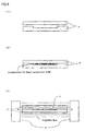
- the composition is charged into a plate shape die of 15mm in thickness, 20mm in length and 20 mm in width, boron nitride powder is oriented sufficiently under the magnetic field atmosphere where N pole and S pole of 6 tesla in flux density are opposed in the thickness direction, and heat set, to obtain a hard plate shape heat conductive mold as shown in Fig. 5(1), Fig. 5(2) and Fig. 5 (3).
- the heat resistance value of the obtained heat conductive mold was 0.21 °C/W.
- a composition is prepared by blending 100 weight parts of liquid epoxy resin (made by Three Bond Co., Ltd. TB2280C) and 180 weight parts of hexagonal crystalline system granular boron nitride powder (Showa Denko Co., Ltd. UHP-EX average particle diameter 35 ⁇ m).
- the composition is charged into a plate shape die of 15mm in thickness, 20mm in length and 20 mm in width, and heat set, to obtain a hard plate shape heat conductive mold.
- the heat resistance value of the obtained heat conductive mold was 0.32°C/W.
- a composition is prepared by blending 100 weight parts of solid portion of polyimide varnish containing N methyl pyrrolidone as solvent (made by Ube Kosan Co., Ltd., Yupifine ST, concentration of solid portion 18.5%) and 60 weight parts of hexagonal crystalline system flake form boron nitride powder (made by Showa Denko Co., Ltd. UHP-S1 average particle diameter 1 to 2 ⁇ m).
- the composition is charged into a box die of 20mm in length, 20 mm in width and 40 mm in depth, boron nitride powder is oriented sufficiently under the magnetic field atmosphere where N pole and S pole of 6 tesla in flux density are opposed in the thickness direction, and heat set after having removed solvent N methyl pyrrolidone, to obtain a film shape heat conductive mold of 120 ⁇ m in thickness.
- the heat resistance value of the obtained heat conductive mold was 0.18°C/W.
- a composition is prepared by blending 100 weight parts of solid portion of polyimide varnish containing N methyl pyrrolidone as solvent (made by Ube Kosan Co., Ltd., Yupifine ST, concentration of solid portion 18.5%) and 60 weight parts of hexagonal crystalline system flake form boron nitride powder
- the composition is charged into a box die of 20mm in length, 20 mm in width and 40 mm in depth, and heat set after having removed solvent N methyl pyrrolidone, to obtain a film shape heat conductive mold of 120 ⁇ m in thickness.
- the heat resistance value of the obtained heat conductive mold was 0.27°C/W.
- Comparison Example 1 Comparison Example 3 are conventional molds wherein flake form boron nitride powder is charged into polymer, and Comparison Example 2 is one wherein granular boron nitride powder is charged, and they present a high heat resistance value.
- the heat conductive mold of Example 1, Example 2, Example 3 of the present invention are obtained by impressing magnetic field to the polymer composition containing the same amount of flake form boron nitride powder or granular boron nitride powder as the corresponding Comparison Example, field orienting boron nitride powder in the composition, and then heat setting, and each presents smaller heat resistance value and better heat conductivity than the corresponding Comparison Example.
- the present invention allows to produce a heat conductive mold of excellent heat conductivity, by impressing magnetic field to the polymer composition containing in particular flake form boron nitride powder or granular boron nitride powder, field orienting boron nitride powder in the composition to a fixed direction, and then heat setting.
- heat conductive mold of the present invention various radiation components requiring a high heat conductivity such as high heat value CPU (central processing unit) or other semiconductors, power source, light source, plasma display, printed circuit board or the like can be supplied.
- CPU central processing unit
- other semiconductors power source, light source, plasma display, printed circuit board or the like.
Landscapes
- Compositions Of Macromolecular Compounds (AREA)
- Cooling Or The Like Of Semiconductors Or Solid State Devices (AREA)
- Moulds For Moulding Plastics Or The Like (AREA)
- Manufacture Of Macromolecular Shaped Articles (AREA)
- Moulding By Coating Moulds (AREA)
Claims (6)
- Procédé de fabrication d'un moule conducteur de chaleur, par application d'un champ magnétique sur une composition polymère contenant de la poudre de nitrure de bore sous forme de lamelle, sous forme plate, sous forme granulaire, sous forme agrégée, sous forme de fibre ou sous forme de trichite, orientation dans le champ de la poudre de nitrure de bore de la composition dans une direction alignée avec une direction d'une ligne de force magnétique, puis durcissement de celle-ci,
dans lequel l'étape d'orientation dans le champ comprend l'orientation de la poudre de nitrure de bore pour augmenter la conductivité thermique du moule dans ladite direction au moyen de l'anisotropie magnétique caractéristique de la poudre de nitrure de bore, et
dans lequel la proportion de poudre de nitrure de bore est de 20 à 400 parties en poids pour 100 parties en poids de polymère. - Procédé de fabrication d'un moule conducteur de chaleur selon la revendication 1, dans lequel le polymère est au moins un polymère choisi parmi le caoutchouc de silicium, l'époxy, le polyimide et le polyuréthane.
- Procédé selon la revendication 1 ou 2, comprenant en outre l'application d'un champ magnétique sur une composition polymère contenant de la poudre de nitrure de bore et un solvant, puis le durcissement de celle-ci après avoir éliminé le solvant.
- Procédé selon l'une quelconque des revendications 1 à 3, dans lequel le diamètre primaire moyen individuel de la poudre de nitrure de bore se situe dans la gamme de 0,01 à 100 µm.
- Procédé selon la revendication 1, dans lequel une direction de ligne de force magnétique est disposée dans le sens de l'épaisseur d'une feuille (direction verticale par rapport à la surface d'une feuille) dans le cas d'une composition polymère façonnée en feuille contenant de la poudre de nitrure de bore.
- Procédé selon la revendication 1, dans lequel une direction de ligne de force magnétique est disposée dans une direction fixe le long de la surface d'une feuille dans le cas d'une composition polymère façonnée en feuille contenant de la poudre de nitrure de bore.
Applications Claiming Priority (2)
| Application Number | Priority Date | Filing Date | Title |
|---|---|---|---|
| JP35864699 | 1999-12-17 | ||
| JP35864699A JP2001172398A (ja) | 1999-12-17 | 1999-12-17 | 熱伝導性成形体およびその製造方法 |
Publications (3)
| Publication Number | Publication Date |
|---|---|
| EP1109218A2 EP1109218A2 (fr) | 2001-06-20 |
| EP1109218A3 EP1109218A3 (fr) | 2003-04-02 |
| EP1109218B1 true EP1109218B1 (fr) | 2010-12-01 |
Family
ID=18460395
Family Applications (1)
| Application Number | Title | Priority Date | Filing Date |
|---|---|---|---|
| EP00310713A Expired - Lifetime EP1109218B1 (fr) | 1999-12-17 | 2000-12-01 | Moule conducteur de chaleur et procédé de sa fabrication |
Country Status (4)
| Country | Link |
|---|---|
| US (2) | US20010004546A1 (fr) |
| EP (1) | EP1109218B1 (fr) |
| JP (1) | JP2001172398A (fr) |
| DE (1) | DE60045301D1 (fr) |
Cited By (3)
| Publication number | Priority date | Publication date | Assignee | Title |
|---|---|---|---|---|
| US8561934B2 (en) | 2009-08-28 | 2013-10-22 | Teresa M. Kruckenberg | Lightning strike protection |
| US8752279B2 (en) | 2007-01-04 | 2014-06-17 | Goodrich Corporation | Methods of protecting an aircraft component from ice formation |
| US8962130B2 (en) | 2006-03-10 | 2015-02-24 | Rohr, Inc. | Low density lightning strike protection for use in airplanes |
Families Citing this family (53)
| Publication number | Priority date | Publication date | Assignee | Title |
|---|---|---|---|---|
| JP2002069392A (ja) * | 2000-08-31 | 2002-03-08 | Polymatech Co Ltd | 熱伝導性接着フィルムおよびその製造方法ならびに電子部品 |
| JP2003060134A (ja) * | 2001-08-17 | 2003-02-28 | Polymatech Co Ltd | 熱伝導性シート |
| US6921462B2 (en) | 2001-12-17 | 2005-07-26 | Intel Corporation | Method and apparatus for producing aligned carbon nanotube thermal interface structure |
| US6965513B2 (en) * | 2001-12-20 | 2005-11-15 | Intel Corporation | Carbon nanotube thermal interface structures |
| US6856016B2 (en) | 2002-07-02 | 2005-02-15 | Intel Corp | Method and apparatus using nanotubes for cooling and grounding die |
| US7067903B2 (en) * | 2002-11-07 | 2006-06-27 | Kabushiki Kaisha Kobe Seiko Sho | Heat spreader and semiconductor device and package using the same |
| US7316061B2 (en) | 2003-02-03 | 2008-01-08 | Intel Corporation | Packaging of integrated circuits with carbon nano-tube arrays to enhance heat dissipation through a thermal interface |
| US7168484B2 (en) | 2003-06-30 | 2007-01-30 | Intel Corporation | Thermal interface apparatus, systems, and methods |
| US7031162B2 (en) * | 2003-09-26 | 2006-04-18 | International Business Machines Corporation | Method and structure for cooling a dual chip module with one high power chip |
| KR100581863B1 (ko) * | 2003-10-09 | 2006-05-22 | 삼성에스디아이 주식회사 | 플라즈마 디스플레이 장치 |
| US20050083641A1 (en) * | 2003-10-21 | 2005-04-21 | Shu-Ju Lin | Central processing unit |
| US7456052B2 (en) | 2003-12-30 | 2008-11-25 | Intel Corporation | Thermal intermediate apparatus, systems, and methods |
| US7180174B2 (en) | 2003-12-30 | 2007-02-20 | Intel Corporation | Nanotube modified solder thermal intermediate structure, systems, and methods |
| JP2005331945A (ja) * | 2004-05-18 | 2005-12-02 | Samsung Sdi Co Ltd | プラズマ表示装置 |
| JP2006273948A (ja) * | 2005-03-28 | 2006-10-12 | Mitsui Chemicals Inc | 熱伝導性樹脂組成物およびその用途 |
| JP4747926B2 (ja) * | 2005-05-25 | 2011-08-17 | 東ソー株式会社 | ポリアリーレンスルフィド組成物 |
| JP2009510716A (ja) * | 2005-08-26 | 2009-03-12 | クール オプションズ,インコーポレーテッド | 超小型電子機器のダイレベル・パッケージング用熱伝導性サーモプラスチック |
| KR100646404B1 (ko) * | 2005-10-26 | 2006-11-14 | 주식회사 만도 | 전자 제어 장치 및 이를 구비한 자동차의 전기식 동력 보조조향장치 |
| JP4747918B2 (ja) | 2005-11-04 | 2011-08-17 | 東ソー株式会社 | ポリアリーレンスルフィド組成物 |
| JP2007286785A (ja) * | 2006-04-14 | 2007-11-01 | Fujitsu Ltd | 電子機器および冷却部品 |
| JP4747931B2 (ja) * | 2006-04-25 | 2011-08-17 | 東ソー株式会社 | ポリアリーレンスルフィド組成物 |
| JP2007291300A (ja) * | 2006-04-27 | 2007-11-08 | Tosoh Corp | ポリアリーレンスルフィド組成物 |
| EP2660385B1 (fr) | 2006-05-02 | 2018-07-04 | Goodrich Corporation | Materiau de protection contre la foudre |
| WO2008042446A2 (fr) * | 2006-10-07 | 2008-04-10 | Momentive Performance Materials, Inc. | Composition mixte à base de nitrure de bore et son procédé de préparation |
| WO2008085999A1 (fr) * | 2007-01-10 | 2008-07-17 | Momentive Performance Materials Inc. | Matériaux d'inteface thermique et procédés de fabrication de ces derniers |
| JP5042899B2 (ja) * | 2008-03-31 | 2012-10-03 | ポリマテック株式会社 | 熱伝導性シート及びその製造方法 |
| US7906376B2 (en) * | 2008-06-30 | 2011-03-15 | Intel Corporation | Magnetic particle-based composite materials for semiconductor packages |
| JP5308859B2 (ja) * | 2008-10-20 | 2013-10-09 | 株式会社カネカ | 高耐光性高熱伝導性照明器具用樹脂成形体 |
| US8277936B2 (en) * | 2008-12-22 | 2012-10-02 | E I Du Pont De Nemours And Company | Hexagonal boron nitride compositions characterized by interstitial ferromagnetic layers, process for preparing, and composites thereof with organic polymers |
| US8784980B2 (en) * | 2009-05-13 | 2014-07-22 | E I Du Pont De Nemours And Company | Film prepared from a casting composition comprising a polymer and surface modified hexagonal boron nitride particles |
| JP5646823B2 (ja) * | 2009-05-27 | 2014-12-24 | 株式会社カネカ | 高熱伝導性ポリイミドフィルム |
| JP5513840B2 (ja) * | 2009-10-22 | 2014-06-04 | 電気化学工業株式会社 | 絶縁シート、回路基板及び絶縁シートの製造方法 |
| JP5759192B2 (ja) * | 2010-01-29 | 2015-08-05 | 日東電工株式会社 | バックライトおよび液晶表示装置 |
| DE102010050900A1 (de) | 2010-11-10 | 2012-05-10 | Esk Ceramics Gmbh & Co. Kg | Bornitrid-Agglomerate, Verfahren zu deren Herstellung und deren Verwendung |
| US20150274930A1 (en) * | 2012-09-19 | 2015-10-01 | Momentive Performance Materials Inc. | Masterbatch comprising boron nitride, composite powders thereof, and compositions and articles comprising such materials |
| CN102924923B (zh) * | 2012-10-24 | 2014-12-03 | 江苏大学 | 一种高导热磁性金属纤维/硅橡胶复合材料及其制备方法 |
| JP6438701B2 (ja) * | 2014-08-18 | 2018-12-19 | パナソニック株式会社 | 放熱ゴム組成物 |
| US10022896B2 (en) * | 2015-11-23 | 2018-07-17 | The Boeing Company | Controlling the heating of a composite part |
| TWI588251B (zh) | 2015-12-08 | 2017-06-21 | 財團法人工業技術研究院 | 磁性導熱材料與導熱介電層 |
| JP7120229B2 (ja) * | 2017-06-09 | 2022-08-17 | 三菱瓦斯化学株式会社 | 異方性フィラー含有シートの製造方法 |
| EP3460839A1 (fr) * | 2017-09-21 | 2019-03-27 | GWP Gesellschaft Für Werkstoffprüfung MbH | Feuilles pour une utilisation dans la technologie des semi-conducteurs |
| WO2019173660A1 (fr) * | 2018-03-09 | 2019-09-12 | Engi-Mat Co. | Matériaux diélectriques composites thermoconducteurs |
| US12146093B2 (en) * | 2018-05-10 | 2024-11-19 | Georgia Tech Research Corporation | Thermal management materials and methods of making the same |
| US10923412B2 (en) | 2018-08-10 | 2021-02-16 | Cerebras Systems Inc. | Apparatuses and methods for implementing a sliding thermal interface between substrates with varying coefficients of thermal expansion |
| US10811187B2 (en) * | 2018-09-18 | 2020-10-20 | Toyota Motor Engineering & Manufacturing North America, Inc. | Methods of fabricating thermal composites having specifically designed particle distributions |
| JP2020055961A (ja) * | 2018-10-03 | 2020-04-09 | 信越化学工業株式会社 | 制御された熱伝導率分布を有する樹脂シート及びその製造方法 |
| US11450588B2 (en) * | 2019-10-16 | 2022-09-20 | Taiwan Semiconductor Manufacturing Co., Ltd. | Method for forming chip package structure with heat conductive layer |
| KR102702093B1 (ko) * | 2019-11-27 | 2024-09-04 | 삼성전자주식회사 | 반도체 패키지 |
| CN111484627A (zh) * | 2020-04-26 | 2020-08-04 | 赵汉波 | 一种功能化氮化硼原位改性环氧树脂绝缘材料及其制法 |
| CN113150557A (zh) * | 2021-04-08 | 2021-07-23 | 华南理工大学 | 一种定向排列且构建三维结构提高导热性能的硅橡胶复合材料及其制备方法与应用 |
| JP2024006085A (ja) * | 2022-06-30 | 2024-01-17 | 日本ゼオン株式会社 | 複合シート |
| JP7798080B2 (ja) | 2023-05-19 | 2026-01-14 | トヨタ自動車株式会社 | 熱伝導性部材、熱伝導性部材の製造方法、および、電池モジュール |
| TWI910844B (zh) * | 2024-09-25 | 2026-01-01 | 萬潤科技股份有限公司 | 壓合方法及裝置 |
Family Cites Families (17)
| Publication number | Priority date | Publication date | Assignee | Title |
|---|---|---|---|---|
| JPS5029939B2 (fr) * | 1972-07-05 | 1975-09-27 | ||
| ZA741474B (en) * | 1974-03-07 | 1975-10-29 | Edenvale Eng Works | Abrasive tools |
| US4256792A (en) * | 1980-01-25 | 1981-03-17 | Honeywell Inc. | Composite electronic substrate of alumina uniformly needled through with aluminum nitride |
| JPS58152033A (ja) * | 1982-03-04 | 1983-09-09 | Japan Synthetic Rubber Co Ltd | 異方導電性ゴムシ−ト |
| JPS6169866A (ja) * | 1984-09-12 | 1986-04-10 | Polyplastics Co | 複合材料組成物 |
| JPH0612643B2 (ja) * | 1985-12-25 | 1994-02-16 | 信越化学工業株式会社 | 熱伝導性絶縁シ−ト |
| JPH0638460B2 (ja) * | 1989-11-08 | 1994-05-18 | 東海ゴム工業株式会社 | 放熱シート |
| JP3305720B2 (ja) * | 1993-07-06 | 2002-07-24 | 株式会社東芝 | 放熱シート |
| JPH0788971A (ja) * | 1993-09-21 | 1995-04-04 | Tokai Rubber Ind Ltd | 半導電性シート |
| JP3698451B2 (ja) * | 1995-03-13 | 2005-09-21 | 電気化学工業株式会社 | シートの製造方法 |
| JPH1160216A (ja) * | 1997-08-04 | 1999-03-02 | Shin Etsu Chem Co Ltd | 熱伝導性窒化ホウ素フィラー及び絶縁放熱シート |
| JP3434678B2 (ja) * | 1997-09-12 | 2003-08-11 | 電気化学工業株式会社 | ゴムシートの製造方法 |
| JP3372462B2 (ja) * | 1997-11-27 | 2003-02-04 | 電気化学工業株式会社 | ゴムシートの製造方法 |
| JP3283226B2 (ja) * | 1997-12-26 | 2002-05-20 | ポリマテック株式会社 | ホルダーの製造法 |
| JP2000281802A (ja) * | 1999-03-30 | 2000-10-10 | Polymatech Co Ltd | 熱伝導性成形体およびその製造方法ならびに半導体装置 |
| JP4528397B2 (ja) * | 1999-12-17 | 2010-08-18 | ポリマテック株式会社 | 接着方法および電子部品 |
| JP2002069392A (ja) * | 2000-08-31 | 2002-03-08 | Polymatech Co Ltd | 熱伝導性接着フィルムおよびその製造方法ならびに電子部品 |
-
1999
- 1999-12-17 JP JP35864699A patent/JP2001172398A/ja active Pending
-
2000
- 2000-12-01 DE DE60045301T patent/DE60045301D1/de not_active Expired - Lifetime
- 2000-12-01 EP EP00310713A patent/EP1109218B1/fr not_active Expired - Lifetime
- 2000-12-08 US US09/733,559 patent/US20010004546A1/en not_active Abandoned
-
2003
- 2003-02-18 US US10/370,301 patent/US6761842B2/en not_active Expired - Fee Related
Cited By (3)
| Publication number | Priority date | Publication date | Assignee | Title |
|---|---|---|---|---|
| US8962130B2 (en) | 2006-03-10 | 2015-02-24 | Rohr, Inc. | Low density lightning strike protection for use in airplanes |
| US8752279B2 (en) | 2007-01-04 | 2014-06-17 | Goodrich Corporation | Methods of protecting an aircraft component from ice formation |
| US8561934B2 (en) | 2009-08-28 | 2013-10-22 | Teresa M. Kruckenberg | Lightning strike protection |
Also Published As
| Publication number | Publication date |
|---|---|
| US20030153665A1 (en) | 2003-08-14 |
| DE60045301D1 (de) | 2011-01-13 |
| JP2001172398A (ja) | 2001-06-26 |
| EP1109218A2 (fr) | 2001-06-20 |
| US6761842B2 (en) | 2004-07-13 |
| EP1109218A3 (fr) | 2003-04-02 |
| US20010004546A1 (en) | 2001-06-21 |
Similar Documents
| Publication | Publication Date | Title |
|---|---|---|
| EP1109218B1 (fr) | Moule conducteur de chaleur et procédé de sa fabrication | |
| JP2002080617A (ja) | 熱伝導性シート | |
| EP1108766B1 (fr) | Méthode d'adhésion et composant électronique | |
| US6660566B2 (en) | Heat conductive molded body and manufacturing method thereof and semiconductor device | |
| US6663969B2 (en) | Heat conductive adhesive film and manufacturing method thereof and electronic component | |
| US7264869B2 (en) | Thermally conductive molded article and method of making the same | |
| JP2003321554A (ja) | 熱伝導性成形体及びその製造方法 | |
| CN1893803A (zh) | 散热部件及其制造方法 | |
| CN109891577B (zh) | 导热片和半导体装置 | |
| JP2000195998A (ja) | 熱伝導性シ―トおよびその製造方法ならびに半導体装置 | |
| JP2002088171A (ja) | 熱伝導性シートおよびその製造方法ならびに放熱装置 | |
| CN102290384A (zh) | 绝缘构件、金属基底衬底、半导体模块及其制造方法 | |
| JP2000281995A (ja) | 熱伝導性接着フィルムおよび半導体装置 | |
| CN108659536B (zh) | 导热材料及其制备方法 | |
| JP2000191987A (ja) | 熱伝導性接着フィルムおよび半導体装置 | |
| US20240120254A1 (en) | Thermally-conductive sheet and electronic device | |
| JP2000273426A (ja) | 熱伝導性接着剤および接着方法ならびに半導体装置 | |
| JP3640524B2 (ja) | 放熱スペーサー | |
| KR20140094294A (ko) | 전기 절연성 방열 시트 | |
| KR20140085053A (ko) | 방열 접착테이프 조성물과 방열 접착테이프 및 이를 제조하는 방법 | |
| JP7798080B2 (ja) | 熱伝導性部材、熱伝導性部材の製造方法、および、電池モジュール | |
| JPH03273039A (ja) | 高熱伝導性封止材料 | |
| TWI382083B (zh) | 熱介面材料之製備方法 | |
| JP2007084705A (ja) | 樹脂組成物とこれを用いた回路基板およびパッケージ |
Legal Events
| Date | Code | Title | Description |
|---|---|---|---|
| PUAI | Public reference made under article 153(3) epc to a published international application that has entered the european phase |
Free format text: ORIGINAL CODE: 0009012 |
|
| AK | Designated contracting states |
Kind code of ref document: A2 Designated state(s): AT BE CH CY DE DK ES FI FR GB GR IE IT LI LU MC NL PT SE TR |
|
| AX | Request for extension of the european patent |
Free format text: AL;LT;LV;MK;RO;SI |
|
| 17P | Request for examination filed |
Effective date: 20011113 |
|
| PUAL | Search report despatched |
Free format text: ORIGINAL CODE: 0009013 |
|
| AK | Designated contracting states |
Kind code of ref document: A3 Designated state(s): AT BE CH CY DE DK ES FI FR GB GR IE IT LI LU MC NL PT SE TR Designated state(s): AT BE CH CY DE DK ES FI FR GB GR IE IT LI LU MC NL PT SE TR |
|
| AX | Request for extension of the european patent |
Extension state: AL LT LV MK RO SI |
|
| RIC1 | Information provided on ipc code assigned before grant |
Ipc: 7H 01L 21/48 B Ipc: 7H 01L 23/433 B Ipc: 7H 01L 23/373 A |
|
| AKX | Designation fees paid |
Designated state(s): DE GB NL |
|
| 17Q | First examination report despatched |
Effective date: 20050309 |
|
| GRAP | Despatch of communication of intention to grant a patent |
Free format text: ORIGINAL CODE: EPIDOSNIGR1 |
|
| RIN1 | Information on inventor provided before grant (corrected) |
Inventor name: KIMURA, TSUNEHISAEXCEL HEIGHTS 301, Inventor name: YAMATO, MASAHUMI, Inventor name: TATEDA, SHINYA,R&D CENTER OF POLYMATCH CO., LTD Inventor name: TOBITA, MASAYUKI,R&D CENTER OF POLYMATCH CO., LTD |
|
| GRAS | Grant fee paid |
Free format text: ORIGINAL CODE: EPIDOSNIGR3 |
|
| GRAA | (expected) grant |
Free format text: ORIGINAL CODE: 0009210 |
|
| AK | Designated contracting states |
Kind code of ref document: B1 Designated state(s): DE GB NL |
|
| REG | Reference to a national code |
Ref country code: GB Ref legal event code: FG4D |
|
| REF | Corresponds to: |
Ref document number: 60045301 Country of ref document: DE Date of ref document: 20110113 Kind code of ref document: P |
|
| REG | Reference to a national code |
Ref country code: NL Ref legal event code: VDEP Effective date: 20101201 |
|
| PG25 | Lapsed in a contracting state [announced via postgrant information from national office to epo] |
Ref country code: NL Free format text: LAPSE BECAUSE OF FAILURE TO SUBMIT A TRANSLATION OF THE DESCRIPTION OR TO PAY THE FEE WITHIN THE PRESCRIBED TIME-LIMIT Effective date: 20101201 |
|
| PGFP | Annual fee paid to national office [announced via postgrant information from national office to epo] |
Ref country code: DE Payment date: 20110202 Year of fee payment: 11 |
|
| PGFP | Annual fee paid to national office [announced via postgrant information from national office to epo] |
Ref country code: GB Payment date: 20110202 Year of fee payment: 11 |
|
| PLBE | No opposition filed within time limit |
Free format text: ORIGINAL CODE: 0009261 |
|
| STAA | Information on the status of an ep patent application or granted ep patent |
Free format text: STATUS: NO OPPOSITION FILED WITHIN TIME LIMIT |
|
| 26N | No opposition filed |
Effective date: 20110902 |
|
| REG | Reference to a national code |
Ref country code: DE Ref legal event code: R097 Ref document number: 60045301 Country of ref document: DE Effective date: 20110902 |
|
| GBPC | Gb: european patent ceased through non-payment of renewal fee |
Effective date: 20111201 |
|
| REG | Reference to a national code |
Ref country code: DE Ref legal event code: R119 Ref document number: 60045301 Country of ref document: DE Effective date: 20120703 |
|
| PG25 | Lapsed in a contracting state [announced via postgrant information from national office to epo] |
Ref country code: DE Free format text: LAPSE BECAUSE OF NON-PAYMENT OF DUE FEES Effective date: 20120703 Ref country code: GB Free format text: LAPSE BECAUSE OF NON-PAYMENT OF DUE FEES Effective date: 20111201 |