EP1111149A2 - Procédé et dispostif de fixation des ancres de transport pour éléments de mur préfabriqués - Google Patents
Procédé et dispostif de fixation des ancres de transport pour éléments de mur préfabriqués Download PDFInfo
- Publication number
- EP1111149A2 EP1111149A2 EP00128262A EP00128262A EP1111149A2 EP 1111149 A2 EP1111149 A2 EP 1111149A2 EP 00128262 A EP00128262 A EP 00128262A EP 00128262 A EP00128262 A EP 00128262A EP 1111149 A2 EP1111149 A2 EP 1111149A2
- Authority
- EP
- European Patent Office
- Prior art keywords
- wall panel
- wall
- bricks
- transport
- anchor
- Prior art date
- Legal status (The legal status is an assumption and is not a legal conclusion. Google has not performed a legal analysis and makes no representation as to the accuracy of the status listed.)
- Withdrawn
Links
- 238000000034 method Methods 0.000 title claims description 15
- 239000011449 brick Substances 0.000 claims abstract description 52
- 238000005553 drilling Methods 0.000 claims abstract description 17
- 239000011230 binding agent Substances 0.000 claims description 16
- 230000000694 effects Effects 0.000 claims description 5
- 230000002787 reinforcement Effects 0.000 claims description 3
- 230000015572 biosynthetic process Effects 0.000 claims description 2
- 238000006073 displacement reaction Methods 0.000 claims 1
- 239000007767 bonding agent Substances 0.000 abstract 1
- 239000004570 mortar (masonry) Substances 0.000 description 20
- 238000004519 manufacturing process Methods 0.000 description 13
- 238000010276 construction Methods 0.000 description 8
- 239000004575 stone Substances 0.000 description 8
- 238000009413 insulation Methods 0.000 description 7
- 239000000725 suspension Substances 0.000 description 3
- 230000002745 absorbent Effects 0.000 description 2
- 239000002250 absorbent Substances 0.000 description 2
- 230000005484 gravity Effects 0.000 description 2
- 238000004873 anchoring Methods 0.000 description 1
- 230000005540 biological transmission Effects 0.000 description 1
- 238000004364 calculation method Methods 0.000 description 1
- 238000005266 casting Methods 0.000 description 1
- 239000011093 chipboard Substances 0.000 description 1
- 238000004140 cleaning Methods 0.000 description 1
- 238000005520 cutting process Methods 0.000 description 1
- 230000001419 dependent effect Effects 0.000 description 1
- 238000005516 engineering process Methods 0.000 description 1
- 238000009434 installation Methods 0.000 description 1
- 239000011470 perforated brick Substances 0.000 description 1
- 239000011505 plaster Substances 0.000 description 1
- 238000003825 pressing Methods 0.000 description 1
- 238000003860 storage Methods 0.000 description 1
- 239000002699 waste material Substances 0.000 description 1
Images


Classifications
-
- E—FIXED CONSTRUCTIONS
- E04—BUILDING
- E04C—STRUCTURAL ELEMENTS; BUILDING MATERIALS
- E04C2/00—Building elements of relatively thin form for the construction of parts of buildings, e.g. sheet materials, slabs, or panels
- E04C2/02—Building elements of relatively thin form for the construction of parts of buildings, e.g. sheet materials, slabs, or panels characterised by specified materials
- E04C2/04—Building elements of relatively thin form for the construction of parts of buildings, e.g. sheet materials, slabs, or panels characterised by specified materials of concrete or other stone-like material; of asbestos cement; of cement and other mineral fibres
- E04C2/041—Building elements of relatively thin form for the construction of parts of buildings, e.g. sheet materials, slabs, or panels characterised by specified materials of concrete or other stone-like material; of asbestos cement; of cement and other mineral fibres composed of a number of smaller elements, e.g. bricks, also combined with a slab of hardenable material
-
- E—FIXED CONSTRUCTIONS
- E04—BUILDING
- E04G—SCAFFOLDING; FORMS; SHUTTERING; BUILDING IMPLEMENTS OR AIDS, OR THEIR USE; HANDLING BUILDING MATERIALS ON THE SITE; REPAIRING, BREAKING-UP OR OTHER WORK ON EXISTING BUILDINGS
- E04G21/00—Preparing, conveying, or working-up building materials or building elements in situ; Other devices or measures for constructional work
- E04G21/14—Conveying or assembling building elements
- E04G21/142—Means in or on the elements for connecting same to handling apparatus
-
- E—FIXED CONSTRUCTIONS
- E04—BUILDING
- E04G—SCAFFOLDING; FORMS; SHUTTERING; BUILDING IMPLEMENTS OR AIDS, OR THEIR USE; HANDLING BUILDING MATERIALS ON THE SITE; REPAIRING, BREAKING-UP OR OTHER WORK ON EXISTING BUILDINGS
- E04G21/00—Preparing, conveying, or working-up building materials or building elements in situ; Other devices or measures for constructional work
- E04G21/14—Conveying or assembling building elements
- E04G21/142—Means in or on the elements for connecting same to handling apparatus
- E04G21/147—Means in or on the elements for connecting same to handling apparatus specific for prefabricated masonry wall elements
-
- E—FIXED CONSTRUCTIONS
- E04—BUILDING
- E04G—SCAFFOLDING; FORMS; SHUTTERING; BUILDING IMPLEMENTS OR AIDS, OR THEIR USE; HANDLING BUILDING MATERIALS ON THE SITE; REPAIRING, BREAKING-UP OR OTHER WORK ON EXISTING BUILDINGS
- E04G21/00—Preparing, conveying, or working-up building materials or building elements in situ; Other devices or measures for constructional work
- E04G21/14—Conveying or assembling building elements
- E04G21/16—Tools or apparatus
-
- E—FIXED CONSTRUCTIONS
- E04—BUILDING
- E04C—STRUCTURAL ELEMENTS; BUILDING MATERIALS
- E04C2/00—Building elements of relatively thin form for the construction of parts of buildings, e.g. sheet materials, slabs, or panels
- E04C2002/001—Mechanical features of panels
- E04C2002/002—Panels with integrated lifting means, e.g. with hoisting lugs
Definitions
- the invention relates to a method for fastening of transport anchors on wall panels according to the generic term of Claim 1 and an apparatus for performing this method.
- Wall boards are factory-made according to the construction plans of the masonry building to be built, to which transported to the respective construction site and there to the one to be created Building put together. To do this, the finished wall panels be moved with a crane or the like.
- risers can also be used at a distance from the necessary suspensions around the wall elements be looped and an eyelet to hang on the top of the wall own transport hooks.
- One more way is the use of transport chains that are fixed to bolts are which are put through the wall at the foot of the wall.
- the transport chains have supporting beams on the wall crown.
- belts and transport chains both have the disadvantage that because of their high cost of moving the elements are transported back to the factory for reuse Need to become.
- the object of the invention is, in particular for the automated factory production of wall panels a process and a device for the introduction of transport anchors under To avoid the disadvantages described above.
- holes are drilled in the bricks the transport anchors depending on the position of the bricks introduced in the wall panel, such that the holes in the stacked bricks of the wall panel aligned with each other, i.e. over the entire height the vertical panel recesses extending the wall panel form.
- Standard masonry blocks can therefore be used without grid holes be, while preparing the stones for bricking at the locations provided for the transport anchors in the holes corresponding to individual stones are drilled.
- the Places provided for the lifting anchors are dependent determined by the position that the corresponding brick will take later in the wall panel.
- two holes can be made in a wall panel with 5 cm diameter at a distance from the required transport anchors from e.g. 2.5 m can be introduced, whereby for the Brick tolerance no addition to the bore diameter necessary is. There is no measurable reduction due to the two holes thermal insulation of a 38 cm thick outer wall.
- the masonry drilling device for drilling the transport anchor holes into the bricks by a control device controlled so that the lifting anchor holes in the bricks of superimposed rows of brick aligned with each other in a wall panel.
- the control device can determine the location of a brick take this in the wall row or in the finished wall panel will determine, and depending on this, the drilling device control and position. This can do this at least along the row of brick blocks designed to be relatively movable his.
- An alternative to the movable drilling device is one stationary drilling device integrated in the stone cut represents.
- the drilling device is expediently the line-up section for the stones assigned to a row of walls, so that the holes inserted in the bricks for the transport anchors can be if they are next to each other on the line lined up according to their later arrangement in the wall panel are.
- the bores or holes can already be made in the Production can be brought into the stone factory. This without the Disadvantage of the loss of thermal insulation of the wall Bricks with grid holes if in the production of Wall boards a line-up device for the production of a Wall board row is used, which is able to between Sort whole stones without a hole. So that the holes are in the intended place in the wall, it may be necessary to cut the perforated bricks to length.
- the respective brick line is then preferably with a Relocation gripper from the line to the wall station offset to wall up the wall panel.
- a wall panel at the wall station are preferred Transport anchors formed by rods into the passage recesses poured.
- the invention when pouring the transport anchor of the mortar or the other binder is introduced through a pipe, the is inserted into the through recess.
- this pipe up to the wall base in the passage recess introduced.
- the pipe to be cast is in the pipe Lifting anchor.
- the pipe from the wall panel is pulled, mortar or the like. is pressed through the pipe.
- the transport anchor remains in the wall. Protected the mortar or other binding agent can pass through the pipe do not get stuck prematurely due to the absorbent brick.
- the Pressing the binder into the tube from a binder source is preferably done with a pump via a binder feed.
- bricks are placed in the designated places walled with pre-drilled holes.
- Binder that when moving the bricks in the area of these holes is removed the mentioned pipe preferably at its end with a drill bit equipped and rotating at the wall station in the pre-drilled anchor holes in the wall panel lowered.
- the wall panel is preferably on a foot beam erected.
- the bricks are on beam elements extending along the wall panel bricked up, spaced apart and through a reinforcement are connected.
- the transport anchors are then through the passage recesses into the space stuck between the two foot beam elements and the space above the passage recesses or that mentioned Pipe also filled with the binder.
- the foot beam also provides a stiffening of the blackboard in the area of recesses, e.g. Doors, dar. The amount of It is sensible to choose foot beams less than the screed height.
- the foot beam not only improves the stability of the whole Wall improves, but also prevents stones fall down when transporting wall panels with one Crane commutes the wall panel against the building.
- a under the wall panel arranged two foot beams along the wall panel extending at a distance arranged footboard elements be provided on which the bricks are bricked up be, using a transport anchor, the lower end that is in the space between the two Joist elements, e.g. spirally curved is.
- the gap there is at least one along the wall slab extending longitudinal rod inserted.
- the curved end of the lifting anchor in the space becomes in brought a position under the longitudinal bar, for example by rotating the lifting anchor around its longitudinal axis. After filling the gap through the passage recess with binding agent becomes a firm connection between the horizontal longitudinal bar and the vertical one Transport anchor manufactured.
- a transport anchor with a ribbed surface can also be used with the ribbed end at such a distance applied to the longitudinal bar that an anchoring effect arises in concrete. That means that the anchorage can also be done without a lower trimmed end of the lifting anchor is made, if the vertical anchor rod is close enough to that Longitudinal bar lies, so that the shear force transmission of the concrete is sufficient. In other words, it is essential Formation of the lower end of the rod-shaped lifting anchor, that he is brought into operative connection with the longitudinal bar becomes.
- Clamping grabs are preferably used to transport the wall panels used that grab the lifting anchor and under clamp the effect of the load of the raised wall panel. Such clamp grippers are used, for example, for clamping Bars in testing machines to determine the breaking strength of Rods inserted. Clamping grabs have the advantage that in the wall panels no expensive anchors with pressed on them Hook loops need to be poured in as is the state of the art Technology is that automated gripping of the Wall boards is very easy and that even Lifting a wall by clamping several at the same time Anchor rods is possible if one equipped with several clamps Hanger is used.
- Such a transport sling is preferably with the Wall production control unit connected. Because of The known position of the anchor holes will automatically become grippers move to the position of the cast anchor rods. In conjunction with positionable lifting devices the transportation of the hardened, from the manufacturing pallets Wall panels to be lifted to the rework stations and automate their loading. To be eccentric The main focus is to hang the wall panel horizontally force, a driven pulley is provided, through the different lengths of chain pieces to the fixed point on the lifting beam to compensate for the center of gravity eccentricity can be.
- wall panel 1 has a plant for the production of wall panels 1 a e.g. trained as a conveyor belt or roller conveyor Line up 2 on which the bricks 3 one Brick line 4 can be lined up in a row, as well as one Wall station 5, at which the wall panel 1 from the brick rows 4 is bricked up.
- wall panels 1 a e.g. trained as a conveyor belt or roller conveyor Line up 2 on which the bricks 3 one Brick line 4 can be lined up in a row, as well as one Wall station 5, at which the wall panel 1 from the brick rows 4 is bricked up.
- Wall panel 1 is one shown schematically in FIG. 1 Offset gripper 7 provided.
- the mortar application between the bricks 3 of a brick row 4 and between the brick line 4 when bricking can for example while moving the brick line 4 from the Line up 2 to wall station 5.
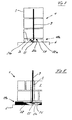
- the wall panel 1 bricked up at the wall station 5 is included Through channels or recesses 8 are provided extend vertically over the entire height of the wall panel 1 (Figs. 1 and 3). In the passage recesses 8 are the formed by rods transport anchor 9 for transporting the finished wall panels 1 embedded.
- the holes 12 in each row of walls 4 that on the line 2 for the production of the wall panel 1 lined up are aligned after bricking up at wall station 5 with each other so that the passage recesses 8 result.
- the drilling device 11 is operated by a not shown Control device controlled accordingly.
- the Control device determines this based on the calculation of the The focus of the wall plate 1 is the location of the lifting anchor 9 should take later and thus determines which position the respective drilled brick 3 in the finished wall panel 1 will take.
- the transport anchor 9 In order to wall the transport anchor 9 into the passage recesses 8, are the transport anchor 9 in the passage recesses 8 introduced. Thereupon a mortar pipe 13 via the transport anchor 9 into the passage recess 8 pushed, as seen in Fig. 3.
- the mortar pipe 13 has an inner diameter that is larger than the outer diameter of the lifting anchor 9.
- the outside diameter of the Mortar tube 13 corresponds essentially to that of the through recess 8, so that the mortar pipe 13 runs smoothly in this can be inserted.
- the mortar pipe 13 is up introduced to the wall base in the recess 8.
- a foot beam 19 can be used.
- the bricks 3 according to Fig. 4 on two upright, plate-shaped beam elements 21, 22 bricked up, spaced apart extend along the wall panel 1.
- the elements 21, 22 are connected to each other by a reinforcement 23 and outside or, if necessary, on both sides with thermal insulation 24 Mistake.
- the transport anchor 9 is in the space 25 inserted between the elements 21, 22, through the mortar pipe 13 is filled with mortar 16.
- clamp grippers 26 are used, which the Lifting anchor 9 under the effect of the load of the raised Clamp wall panel 1. 5 there is the clamp gripper 26 from two clamping jaws 27, 28, which are connected by an overhead Joint axis 29 are connected in an eyelet 31, on the the rope or other traction device of the hoist is attached becomes. So that the jaws 27, 28 under the effect of the load Clamp the transport anchor 9, their leadership is conical.
- the conical jaws 27, 28 of the clamping gripper 26 have an angle of approx. 10 ° to 15 ° to the longitudinal axis of the transport anchor.
- the three transport anchor 9th has, with a transport device with a walking beam 32 raised, on which the clamping grippers 26 are arranged movably are. At the two ends of the walking beam 32 is a chain or the like. Traction means 33 attached to a driven Roll 34 is suspended.
- the clamp grippers 26 are controlled from the data processing system of the masonry machine, controlled so that they automatically go to the transport anchors 9 be moved. To have a horizontal center of gravity Tilt the wall panel 1 to ensure the Roller 34 driven accordingly.
- FIG. 6 in contrast to FIG. 5, the eyelet is in the clamp grippers omitted, the clamp grippers 26 each rigid with the associated motor-adjustable, along the lifting beam 32 movable carriages are connected because at This constructive solution ensures that the automatic grippers function safely given is.
- the transport anchor 9 which is inserted into the through recess 8 is spiral or corkscrew-shaped at its lower end 35 curved.
- foot beam elements formed from chipboard concrete lintels 21a, 22a are on one or the other side wall of the Gap 25a, that is, on the two inner sides of the foot beam elements 21a, 22a, longitudinal bars 36, 37 in the upper region inserted, which extend along the wall panel 1.
Landscapes
- Engineering & Computer Science (AREA)
- Architecture (AREA)
- Civil Engineering (AREA)
- Structural Engineering (AREA)
- Mechanical Engineering (AREA)
- Conveying And Assembling Of Building Elements In Situ (AREA)
- Finishing Walls (AREA)
Applications Claiming Priority (2)
| Application Number | Priority Date | Filing Date | Title |
|---|---|---|---|
| DE19962658 | 1999-12-23 | ||
| DE19962658A DE19962658A1 (de) | 1999-12-23 | 1999-12-23 | Verfahren und Vorrichtung zur Befestigung von Transportankern an Mauertafeln |
Publications (2)
| Publication Number | Publication Date |
|---|---|
| EP1111149A2 true EP1111149A2 (fr) | 2001-06-27 |
| EP1111149A3 EP1111149A3 (fr) | 2003-05-14 |
Family
ID=7934264
Family Applications (1)
| Application Number | Title | Priority Date | Filing Date |
|---|---|---|---|
| EP00128262A Withdrawn EP1111149A3 (fr) | 1999-12-23 | 2000-12-22 | Procédé et dispostif de fixation des ancres de transport pour éléments de mur préfabriqués |
Country Status (2)
| Country | Link |
|---|---|
| EP (1) | EP1111149A3 (fr) |
| DE (1) | DE19962658A1 (fr) |
Cited By (2)
| Publication number | Priority date | Publication date | Assignee | Title |
|---|---|---|---|---|
| EP1091055A3 (fr) * | 1999-10-06 | 2003-03-26 | SÜBA Bau Aktiengesellschaft | Elément de paroi préfabriqué |
| EP1449976A1 (fr) | 2003-02-24 | 2004-08-25 | Undrau Anstalt | Elément de paroi préfabriqué, installation et méthode de fabrication |
Family Cites Families (5)
| Publication number | Priority date | Publication date | Assignee | Title |
|---|---|---|---|---|
| DE496524C (de) * | 1928-03-03 | 1930-04-24 | Ingersoll Rand Co | Gesteinsbohrer |
| DE3713333A1 (de) * | 1987-04-21 | 1988-11-10 | Boecker Albert Gmbh & Co Kg | Greifvorrichtung zum transport von baumaterialien wie dachziegeln und dgl. |
| DE4216367C2 (de) * | 1992-05-18 | 2003-03-27 | Undrau Anstalt Eschen | Verfahren und Versetzgerät zur Mauerherstellung aus Mauerelementen |
| EP0609479A1 (fr) * | 1993-02-05 | 1994-08-10 | Rainer M. Schweiger | Elément de mur préfabriqué, transportable avec armature de support, procédé et installation pour la réalisation de tels éléments |
| DE19710564A1 (de) * | 1997-01-03 | 1998-07-23 | Ziegelei Gersthofen Az Baukera | Verfahren zur Herstellung des Tragwerks eines vorgefertigten, transportablen Mauerteils |
-
1999
- 1999-12-23 DE DE19962658A patent/DE19962658A1/de not_active Withdrawn
-
2000
- 2000-12-22 EP EP00128262A patent/EP1111149A3/fr not_active Withdrawn
Non-Patent Citations (1)
| Title |
|---|
| None |
Cited By (2)
| Publication number | Priority date | Publication date | Assignee | Title |
|---|---|---|---|---|
| EP1091055A3 (fr) * | 1999-10-06 | 2003-03-26 | SÜBA Bau Aktiengesellschaft | Elément de paroi préfabriqué |
| EP1449976A1 (fr) | 2003-02-24 | 2004-08-25 | Undrau Anstalt | Elément de paroi préfabriqué, installation et méthode de fabrication |
Also Published As
| Publication number | Publication date |
|---|---|
| EP1111149A3 (fr) | 2003-05-14 |
| DE19962658A1 (de) | 2001-07-05 |
Similar Documents
| Publication | Publication Date | Title |
|---|---|---|
| DE112012004108T5 (de) | Verbaukasten-system und -verfahren | |
| DE102006040092A1 (de) | Anordnung zum Fördern von Beton mit höhenverstellbarem Betonverteilermast | |
| EP1415057A2 (fr) | Structure et procede de construction | |
| EP0872607B1 (fr) | Elément de construction, mur massif fabriqué avec cet élément et sa méthode de construction | |
| DE4126132A1 (de) | Vorgefertigtes, transportables mauerteil mit als tragwerk ausgebildeten armierungen, sowie ein verfahren und eine vorrichtung zum herstellen eines solchen mauerteils | |
| DE10233145A1 (de) | Gebäude und Verfahren | |
| EP0609479A1 (fr) | Elément de mur préfabriqué, transportable avec armature de support, procédé et installation pour la réalisation de tels éléments | |
| EP0350525A1 (fr) | Procédé pour la réalisation de murs de constructions et système de coffrage | |
| EP1111149A2 (fr) | Procédé et dispostif de fixation des ancres de transport pour éléments de mur préfabriqués | |
| DE2651566C2 (de) | Verfahren zum Montieren von Führungsschienen in Aufzugsschachtelementen sowie Einrichtungen zur Durchführung des Verfahrens | |
| DE4216367A1 (de) | Vorgefertigtes Mauerelement aus Ziegeln | |
| DE19500126C1 (de) | Vorrichtung zum Verlegen von großformatigen Decken- und Dachplatten | |
| DE10007450A1 (de) | Montageträgersystem sowie Verfahren zur Befestigung eines Fertigbauteils an einem Gebäudeteil unter Verwendung des Montageträgersystems | |
| DE20312406U1 (de) | Anordnung zur Errichtung von ein- oder mehrgeschossigen Gebäuden | |
| DE1759316A1 (de) | Verfahren zum Bau eines mehrstoeckigen Gebaeudes und Vorrichtung zur Durchfuehrung des Verfahrens | |
| DE2654584B2 (de) | Vorrichtung zur Vorfertigung großflächiger Mauersteinwände | |
| EP4283064B1 (fr) | Procédé d'incorporation et de fixation des rails d'ancrage dans un corps de bâtiment | |
| EP1449976A1 (fr) | Elément de paroi préfabriqué, installation et méthode de fabrication | |
| DE68928472T2 (de) | Verfahren zur herstellung von gespannten betonträgern bzw. -plattenelementen und verstärkungseinrichtungen dafür | |
| EP0977927B1 (fr) | Procede et dispositif pour batir un ouvrage de ma onnerie | |
| EP0480295B1 (fr) | Ensemble pour la construction d'une maison d'habitation ou de vacances | |
| DE2636168A1 (de) | Verfahren und vorrichtung zum erstellen von bauwerken | |
| DE102008061592A1 (de) | Hebezeug | |
| DE19514139A1 (de) | Transportables Wandelement zur Erstellung von Bauwerken | |
| DE3623793A1 (de) | Verfahren und vorrichtungen zum transport von vorgefertigten mauerwerksteilen |
Legal Events
| Date | Code | Title | Description |
|---|---|---|---|
| PUAI | Public reference made under article 153(3) epc to a published international application that has entered the european phase |
Free format text: ORIGINAL CODE: 0009012 |
|
| AK | Designated contracting states |
Kind code of ref document: A2 Designated state(s): AT BE CH CY DE DK ES FI FR GB GR IE IT LI LU MC NL PT SE TR |
|
| AX | Request for extension of the european patent |
Free format text: AL;LT;LV;MK;RO;SI |
|
| PUAL | Search report despatched |
Free format text: ORIGINAL CODE: 0009013 |
|
| RIC1 | Information provided on ipc code assigned before grant |
Ipc: 7B 28D 1/14 B Ipc: 7E 04G 21/16 B Ipc: 7E 04G 21/14 B Ipc: 7E 04C 2/04 A |
|
| AK | Designated contracting states |
Designated state(s): AT BE CH CY DE DK ES FI FR GB GR IE IT LI LU MC NL PT SE TR |
|
| AX | Request for extension of the european patent |
Extension state: AL LT LV MK RO SI |
|
| AKX | Designation fees paid | ||
| REG | Reference to a national code |
Ref country code: DE Ref legal event code: 8566 |
|
| STAA | Information on the status of an ep patent application or granted ep patent |
Free format text: STATUS: THE APPLICATION IS DEEMED TO BE WITHDRAWN |
|
| 18D | Application deemed to be withdrawn |
Effective date: 20031115 |