EP1115020A2 - Telekonverter und Telekonverter mit Funktion zur Reduktion von Vibrationen - Google Patents
Telekonverter und Telekonverter mit Funktion zur Reduktion von Vibrationen Download PDFInfo
- Publication number
- EP1115020A2 EP1115020A2 EP00311135A EP00311135A EP1115020A2 EP 1115020 A2 EP1115020 A2 EP 1115020A2 EP 00311135 A EP00311135 A EP 00311135A EP 00311135 A EP00311135 A EP 00311135A EP 1115020 A2 EP1115020 A2 EP 1115020A2
- Authority
- EP
- European Patent Office
- Prior art keywords
- lens
- positive
- lens group
- negative
- object side
- Prior art date
- Legal status (The legal status is an assumption and is not a legal conclusion. Google has not performed a legal analysis and makes no representation as to the accuracy of the status listed.)
- Withdrawn
Links
Images






Classifications
-
- G—PHYSICS
- G02—OPTICS
- G02B—OPTICAL ELEMENTS, SYSTEMS OR APPARATUS
- G02B27/00—Optical systems or apparatus not provided for by any of the groups G02B1/00 - G02B26/00, G02B30/00
- G02B27/64—Imaging systems using optical elements for stabilisation of the lateral and angular position of the image
- G02B27/646—Imaging systems using optical elements for stabilisation of the lateral and angular position of the image compensating for small deviations, e.g. due to vibration or shake
-
- G—PHYSICS
- G02—OPTICS
- G02B—OPTICAL ELEMENTS, SYSTEMS OR APPARATUS
- G02B13/00—Optical objectives specially designed for the purposes specified below
- G02B13/02—Telephoto objectives, i.e. systems of the type + - in which the distance from the front vertex to the image plane is less than the equivalent focal length
Definitions
- This invention relates to a front tele-converter, and more particularly to a front tele-converter mounted on the object side of a photo-taking lens in order to enlarge its focal length, and also relates to its vibration-reduction technique.
- Front tele-converters conventionally used for video cameras are disclosed in, e.g., Japanese Patent Application Laid-open No.63-210810 and No.3-59508.
- Vibration-reduction techniques for front tele-converters are also disclosed in Japanese Patent Publication No.7-119902 and Japanese Patent Application Laid-open No.9-171205.
- the front tele-converter disclosed in Japanese Patent Application Laid-open No.63-210810 has had a disadvantage that it can attain a good imaging quality with difficulty because of its relatively small number of lenses and a simple construction.
- the front tele-converter disclosed in Japanese Patent Application Laid-open No.3-59508 also has had a disadvantage that it is of low value in practical use because of its afocal magnification which is as low as about 1.46.
- the front tele-converters disclosed in Japanese Patent Publication No.7-119902 and Japanese Patent Application Laid-open No.9-171205 still also have a relatively small number of lenses and a simple construction, also having a low afocal magnification, and can not be said to be high in the basic picture quality itself.
- the front tele-converter disclosed in Japanese Patent Publication No.7-119902 has an afocal magnification of as low as about 1.2 at best, and has had a disadvantage that it is of low value in practical use.
- the front tele-converter disclosed in Japanese Patent Application Laid-open No.9-171205 has a simple construction that its vibration-reduction lens group consists of one negative lens, and hence has had a disadvantage that it can attain a good imaging quality with difficulty.
- an object of the present invention is to provide a front tele-converter that may cause less aberrations and has a superior imaging quality though it has a high magnification.
- the first invention provides a front tele-converter having an afocal magnification higher than 1.9, which is detachably mountable to a photo-taking lens on its object side, wherein;
- second invention another object of the present invention is to provide a front tele-converter that can well correct various aberrations also at the time of vibration reduction and has a superior imaging quality and a superior vibration-reduction quality, though it has a high magnification.
- the second invention provides a front tele-converter having vibration-reduction function, having an afocal magnification higher than 1.9, which is detachably mountable to a photo-taking lens on its object side, wherein;
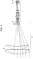
- Fig. 1 illustrates the lens construction of a synthesized optical system consisting of a front tele-converter TC and a photo-taking lens L, according to First Embodiment.
- Figs. 2A to 2D are diagrams showing various aberrations of the synthesized optical system in First Embodiment.
- Fig. 3 illustrates the lens construction of a synthesized optical system consisting of a front tele-converter TC and a photo-taking lens L, according to Second Embodiment.
- Figs. 4A to 4D are diagrams showing various aberrations of the synthesized optical system in Second Embodiment.
- Fig. 5 illustrates the lens construction of a synthesized optical system consisting of a front tele-converter TC and a photo-taking lens L1, according to Third Embodiment.
- Figs. 6A to 6E are diagrams showing various aberrations of the synthesized optical system in Third Embodiment.
- Fig. 7 illustrates the lens construction of a synthesized optical system consisting of a front tele-converter TC and a photo-taking lens L2, according to Fourth Embodiment.
- Figs. 8A to 8E are diagrams showing various aberrations of the synthesized optical system in Fourth Embodiment.
- Figs. 9A and 9B illustrate the lens construction of a synthesized optical system consisting of a front tele-converter TC and a photo-taking lens L2, according to Fifth Embodiment.
- Figs. 10A to 10E are diagrams showing various aberrations of the synthesized optical system in Fifth Embodiment when the photo-taking lens L2 is in a telephoto end state.
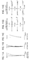
- Figs. 11A to 11E are diagrams showing various aberrations of the synthesized optical system in Fifth Embodiment when the photo-taking lens L2 is in a wide-angle end state.
- Figs. 12A to 12D are diagrams showing various aberrations of a single optical system of a photo-taking lens L1 in Third Embodiment.
- Figs. 13A to 13D are diagrams showing various aberrations of single optical systems in Fourth Embodiment and Fifth Embodiment when the photo-taking lenses L2 are in a telephoto end state.
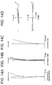
- Figs. 14A to 14D are diagrams showing various aberrations of single optical systems in Fourth Embodiment and Fifth Embodiment when the photo-taking lenses L2 are in a wide-angle end state.
- the front tele-converter is first explained below from a standpoint of optics.
- the front tele-converter refers to an optical system which is mounted to an objective lens on its object side and through which parallel light beam having entered from the object side exits to the image side in parallel.
- an afocal magnification M of the front tele-converter relates to the magnitude of an angle of inclination of an axial paraxial ray, and indicates the ratio of incident side to emergent (exit) side (
- the present invention is concerned with a front tele-converter having an afocal magnification higher than 1.9, i.e., a front tele-converter having the function of what is called telephotographying.
- the front tele-converter of the present invention constitutes a Galilean type optical system. More specifically, it has, in order from the object side, a positive lens group GF having a positive refractive power and a negative lens group GR having a negative refractive power, where the image-side focal point of the positive lens group GF and the object-side focal point of the negative lens group GR are kept in agreement with each other.
- the tele-converter is also called an afocal converter.
- ), i.e., M
- This value of M is determined by paraxial-tracing calculation of only the part of lens data of the front tele-converter. More specifically, the afocal magnification of a front tele-converter depends not on master lenses but on parameters that constitute the front tele-converter.
- the image-side focal point of the positive lens group GF and the object-side focal point of the negative lens group GR need not to be kept in strict agreement.
- the lens may be focused (brought into focus) by moving any one of the positive lens group GF and the negative lens group GR along the optical axis, or the focal points of the both may be kept well close to each other within the range in which the lens can be focused using the rearward photo-taking lens (objective lens).
- the afocal magnification relates to the magnitude of an angle of inclination of an axial paraxial ray and be considered to be the ratio of incident side to emergent side. In such a case the afocal magnification deviates from the formula (a), but may deviate in only a small amount.
- the synthesized focal length of any imaging lens system (assumed to have a focal length f) is given by M ⁇ f, but, when not in agreement, it deviates a little from M ⁇ f.
- the synthesized focal length of the whole optical system is determined by paraxial-ray-tracing calculation.
- the front tele-converter may also include Keplerian type afocal converters in which a positive lens group and an additional positive lens group are combined.
- it may preferably be an afocal converter of the Galilean type described above.
- Galilean type afocal converter is well mountable to photo-taking lenses of cameras or the like because the posture of images does not change also when it is in the state of being mounted.
- the present invention is related, in such Galilean type afocal converters, to a front tele-converter that may cause less aberrations and has a superior imaging quality though it has a high magnification.
- the positive lens group GF has a positive cemented lens
- the negative lens group GR has a positive lens with its convex surface facing the image side
- the lens groups fulfill the following condition (1): 0.5 ⁇ ⁇ F/
- the condition (1) shows an appropriate range for the proportion of an effective aperture OF of a lens surface of the positive lens group GF on its side closest to the object side to a focal length fR of the negative lens group GR.
- This condition (1) specifies the diameter of a light ray that passes through the positive lens group GF which is a front group of the front tele-converter and the focal length of the negative lens group GR which is a rear group, and is a condition important for selectively passing light rays necessary to obtain a sufficiently good image quality and also for controlling the refractive power of the negative lens group GR within a proper range.
- the lens surface of the positive lens group GF on its side closest to the object side has a too large effective aperture ⁇ F, i.e., light rays pass through the positive lens group GF at a too high position, to greatly cause aberrations disadvantageously.
- the front cell diameter (the diameter of a lens disposed closest to the object side) comes to be so large as to not only make the optical system larger but also bring about a disadvantage that the system has a greater weight.
- the lens surface of the positive lens group GF on its side closest to the object side has a too small effective aperture ⁇ F to attain a sufficient quantity of rim (peripheral) light, disadvantageously.
- the upper-limit value of the condition (1) may preferably be 2.5, and the lower-limit value, 0.08.
- the positive lens group GF may also have a positive cemented lens consisting of combination of a negative meniscus lens disposed closest to the object side with its convex surface facing the object side and a positive lens
- the negative lens group GR may have a positive lens disposed closest to the object side and a biconcave lens disposed on the image side of the positive lens
- the lens groups may preferably fulfill the condition (2): 0.03 ⁇ ⁇ R/fF ⁇ 1.0 wherein ⁇ R represents an effective aperture (diameter) of a lens surface of the negative lens group GR on its side closest to the object side; and fF, a focal length of the positive lens group GF.
- the condition (2) shows an appropriate range for the proportion of an effective aperture ⁇ R of a lens surface of the negative lens group GR on its side closest to the object side to a focal length fF of the positive lens group GF.
- the upper-limit value of the condition (2) may preferably be 0.3, and the lower-limit value, 0.08. Also, in the present invention, it has been found that the above condition (2) is effective when the afocal magnification is higher than 1.9.
- the negative lens group GR disposed on the image side, to have a positive lens.
- the negative lens group GR it is important for the negative lens group GR to have a positive lens in order to well correct the Petzval sum when a good flatness of the imaging plane is ensured.
- the positive cemented lens in the positive lens group GF may preferably be constituted of combination of, in order from the object side, a negative meniscus lens with its convex surface facing the object side and a positive lens.
- the front tele-converter of the present invention When the front tele-converter of the present invention is mounted to the photo-taking lens on its object side, a chromatic aberration caused in the tele-converter is added to a chromatic aberration of an original master lens (the photo-taking lens).
- the above constitution of the positive cemented lens is important especially for sufficient axial achromatism in the synthesized optical system (i.e., tele-converter + photo-taking lens).
- the positive lens constituting the positive cemented lens can well correct a spherical aberration and a coma of light rays on the side lower than the principal (chief) ray (a lower coma), and hence, the positive cemented lens constituted as described above is an important requirement for achieving a good imaging quality.
- the positive lens group GF may preferably constituted of, in order from the object side, i) a positive cemented lens consisting of combination of a negative meniscus lens with its convex surface facing the object side and a positive lens and ii) a positive meniscus lens, and the lens groups fulfill the following condition (3): 3.0 ⁇ fF ⁇ M/DFR ⁇ 15.0 wherein fF represents a focal length of the positive lens group GF; M, an afocal magnification of the front tele-converter; and DFR, an axial gap (air gap along the optical axis) between the positive lens group GF and the negative lens group GR.
- Its value greater than the upper-limit value of the condition (3) is undesirable because the positive lens group GF has a too large focal length fF corresponding to the afocal magnification M, so that not only the tele-converter has a large total length, but also the spherical aberration and longitudinal chromatic aberration may greatly occur. Such a value is also not undesirable because a large front cell diameter tends to result to not only make the optical system have a larger size but also make it have a greater weight.
- the positive lens group GF may have so small a focal length as to not only make imaging plane curvature large but also cause a great coma of light rays on the side lower than the principal ray, tending to damage picture quality.
- Such a value is also not undesirable because a large axial gap DFR between the positive lens group GF and the negative lens group GR may result, so that the tele-converter has a large total length.
- the upper-limit value of the condition (3) may preferably be 9.0, and the lower-limit value, 5.0.
- the positive lens group GF may preferably have at least one positive lens formed of a low-dispersive glass. Stated more specifically, the positive lens group GF may preferably have at least one positive lens formed of an optical glass having what is called an Abbe number vd of 65 or more. Such constitution enables sufficient correction of not only longitudinal chromatic aberration but also chromatic aberration of magnification to achieve a good imaging quality. In order to bring out the effect of the present invention more sufficiently, the positive lens group GF may preferably have at least one positive lens formed of an optical glass having an Abbe number vd of 80 or more.
- the positive lens group GF may further preferably have at least one positive lens formed of an optical glass having anomalous dispersion. This is very important for making the tele-converter have a high magnification.
- P(gFdC) (ng - nd)/(nF - nC)
- g, F, d and C each a symbol of a spectral line
- the glass having anomalous dispersion When this relative partial dispersion P(gFdC) and the Abbe number vd are plotted as the ordinate and abscissa of a graph, those standing deviated from the coordinates of normal glass are called the glass having anomalous dispersion.
- the normal glass is typified by, e.g., crown glass and flint glass which are available from Schott Glas. Those standing deviated from a line formed by connecting the coordinates of these two glasses are called the glass having anomalous dispersion.
- the present invention it has been found that in order to effect sufficient achromatism it is very effective to use for the positive lens in the positive lens group GF an optical glass having an Abbe number vd of 80 or more and a relative partial dispersion P(gFdC) of 0.8 or more. It has also been found that forming the positive lens in the positive lens group GF by the use of the low-dispersive glass is more preferable because the effect of achromatism as the cemented lens can sufficiently be brought out. Also, a good achromatic effect can be attained also when the the low-dispersive glass is used for any of the positive lenses in the positive lens group GF.
- the negative lens group GR may also be constituted of, in order from the object side, a cemented lens consisting of combination of a positive meniscus lens, a biconcave lens and a positive meniscus lens, and the refractive index to the d-line of this biconcave lens may preferably fulfill the following condition (4): 1.7 ⁇ nd
- the Petzval sum of the whole optical system tends to be displaced (shifted) to the negative side.
- the imaging plane may greatly be curved to the positive side to make poor the imaging quality around the image undesirably.
- the lower-limit value of the condition (4) may preferably be 1.8.
- the negative lens group GR may preferably fulfill the following conditions (4) and (5): 1.6 ⁇ N -2.0 ⁇ (RB + RA)/(RB - RA) ⁇ 0
- N represents a refractive index to the d-line of a positive lens in the negative lens group GR (when it has a plurality of positive lenses, their average value is found);
- RA represents a radius of curvature of an object-side surface of the biconcave lens in the negative lens group GR; and
- RB represents a radius of curvature of an image-side surface of the biconcave lens in the negative lens group GR.
- the condition (5) specifies an appropriate range for the refractive index to the d-line of the positive lens in the negative lens group GR.
- the positive lens has so small a refractive index N that Petzval sum tends to be on the negative side.
- This condition (5) is effective especially when the afocal magnification is higher than 2.5.
- the condition (6) specifies an appropriate range for a shape factor (SF) of the biconcave lens in the negative lens group GR.
- the shape factor is a parameter that shows the shape of a lens. The lens shape becomes biconcave or meniscus-shaped according to this value.
- the upper-limit value may preferably be -0.1, and the lower-limit value, -0.6.
- the conditions (5) and (6) are also more effective when the afocal magnification is higher than 2.5.
- the positive lens group GF is constituted of, in order from the object side, i) a positive cemented lens consisting of combination of a negative meniscus lens with its convex surface facing the object side and a positive lens and ii) a positive meniscus lens with its convex surface facing the object side, and at least one lens of the positive lens and the positive meniscus lens is formed of a low-dispersive glass having an Abbe number vd of 80 or more.
- both the positive lens and the positive meniscus lens may be formed using the above low-dispersive glass so that a much superior imaging quality can be achieved.
- both the positive lens and the positive meniscus lens may preferably be formed using the glass having anomalous diffusion described above.
- the negative lens group GR may preferably be constituted of, in order from the object side, a cemented lens consisting of combination of a positive meniscus lens, a biconcave lens and a positive meniscus lens.
- the negative lens group GR may preferably be a negative cemented lens consisting of three lenses.
- Such constitution is more effective especially when the afocal magnification M fulfills the following condition (7): 2.5 ⁇ M
- the positive lens in the positive cemented lens in the positive lens group GF, the positive lens may be made to have a large Abbe number to make it low-dispersive and the negative lens may be made to have a small Abbe number to make it high-dispersive, whereby a sufficient axial achromatism can be achieved.
- the Abbe number of the positive lens and that of the negative lens may preferably be set in a difference ⁇ of 10 or larger.
- the difference ⁇ may preferably be 10 or more at minimum.
- the use of a short flint type (KzF system of Schott Glas) anomalous-dispersive glass in any of constituent negative lenses also enables much superior chromatic correction.
- the original photo-taking lens has the characteristic of having an elongated minimum photo-taking distance.
- a mechanism may be provided by which at least one of the positive lens group GF and the negative lens group GR is movable along the optical axis.
- the negative lens group GR may be made up as a movable lens group which can be moved along the optical axis, thus a relatively simple structure can be set up, and also an inner focusing system can be employed in which the total length does not change at the time of focusing. This is advantageous.
- the light ray which exit from the front tele-converter need not to be perfectly afocal, and may substantially be afocal within the range where the focusing can be made.
- the system has a focusing mechanism on the photo-taking lens side, it has a little long back focus when the front tele-converter is mounted, and this rather can make the system absorb changes in temperature or errors in production to enables sure infinite focusing, thus this is preferable from the viewpoint of production technology.
- the front tele-converter of the present invention may further have, as described later, a vibration-detecting member for detecting any vibration of the photo-taking lens, a vibration control device for determining an appropriate amount of vibration correction in accordance with signals sent from the vibration-detecting member and signals sent from a control member for making control of a camera's operating sequence, and a drive mechanism for moving a vibration-reduction lens group in accordance with the amount of vibration correction, which are combined to make up a vibration-reduction lens system.
- the system may preferably be so constructed that a small-sized negative lens group GR or a part thereof may shift in the direction falling at right angles with the optical axis.
- the front tele-converter may preferably be an afocal converter of the Galilean type described above.
- Galilean type afocal converter is well mountable to photo-taking lenses of cameras or the like because the posture of images does not change also when it is in the state of being mounted.
- Keplerian type afocal converters in which a positive lens group and an additional positive lens group are combined is disadvantageous in that it has a large total length and the image is inverted up and down and right and left.
- a vibration-reduction lens group GV comprising a lens group consisting of part or the whole of a negative lens group GR and having a negative refractive power, the negative lens group GR having a stated construction, is moved in the direction falling at substantially right angles with the optical axis.
- a vibration-reduction lens system can be made up by combination of a vibration-detecting member for detecting any vibration of a photo-taking lens, a vibration control device for determining an appropriate amount of vibration correction in accordance with signals sent from the vibration-detecting member and signals sent from a control member for making control of a camera's operating sequence, and a drive mechanism for moving a vibration-reduction lens group in accordance with the amount of vibration correction.
- the positive lens group GF has a positive cemented lens
- the negative lens group GR has a cemented lens comprising a positive lens with its convex surface facing the image side
- the lens groups fulfill the following conditions (8) and (9): ⁇ S/
- ⁇ S represents the maximum amount of movement of the vibration-reduction lens group GV at the time of vibration reduction, in the direction falling at substantially right angles with the optical axis
- fV represents a focal length of the vibration-reduction lens group GV
- fF a focal length of the positive lens group GF.
- the condition (8) specifies an appropriate range for the proportion of the maximum amount ⁇ S of movement of the vibration-reduction lens group GV to the magnitude
- the vibration-reduction lens group GV moves in a too large amount at the time of vibration reduction, so that aberrations may vary in a large amount at the time of vibration reduction disadvantageously.
- a difference between the best imaging plane in the meridional direction and the best imaging plane in the sagittal direction along the optical axis may greatly differ disadvantageously.
- the chromatic aberration of magnification and decentration coma may greatly occur disadvantageously.
- the upper-limit value of the condition (8) may more preferably be set to be 0.05.
- the condition (9) specifies an appropriate range for the proportion of the magnitude
- the vibration-reduction lens group GV has a negative refractive power, and hence fF ⁇ 0.
- the vibration-reduction lens group GV moves in a large amount at the time of vibration reduction, so that not only a disadvantage may be brought about such that the lens aperture tends to have to be made large in order to ensure a given quantity of light, but also the mechanism itself is complicated disadvantageously.
- the vibration-reduction lens group GV has a too strong refractive power, so that aberrations may vary in a large amount at the time of vibration reduction, and especially the image plane tends to lose its flatness, resulting in a low imaging quality. As the result, picture quality around the imaging plane may lower disadvantageously.
- the upper-limit value of the condition (9) may more preferably be set to be 0.8, and the lower-limit value, 0.2.
- the lens groups may preferably fulfill the following conditions (10) and (11): ⁇ S/ ⁇ F ⁇ 0.2 ( 2.0 ⁇ ⁇ F/ ⁇ R ⁇ 10.0 wherein ⁇ F represents an effective aperture (diameter) of a lens surface of the positive lens group GF on its side closest to the object side; and ⁇ R, an effective aperture of a lens surface of the negative lens group GR on its side closest to the object side.
- the condition (10) specifies an appropriate range for the proportion of the maximum amount ⁇ S of movement of the vibration-reduction lens group GV to the effective aperture ⁇ F of a lens surface of the positive lens group GF on its side closest to the object side.
- ⁇ S > 0.
- the vibration-reduction lens group GV moves in a too large amount ⁇ S with respect to the effective aperture ⁇ F at the time of vibration reduction, so that not only the image plane may have a poor flatness but also stray light tends to mix to make picture quality greatly poor undesirably.
- the upper-limit value of the condition (10) may more preferably be set to be 0.05.
- the condition (11) specifies an appropriate range for the proportion of the effective aperture ⁇ F of a lens surface of the positive lens group GF on its side closest to the object side to the effective aperture ⁇ R of a lens surface of the negative lens group GR on its side closest to the object side.
- This condition (11) specifies the diameter of a light ray that passes through the positive lens group GF which is a front group of the front tele-converter and the focal length of the negative lens group GR which is a rear group, and is a condition important for selectively passing light rays necessary to obtain a sufficiently good image and also for controlling the refractive power of the rear group negative lens group GR within a proper range.
- Its value greater than the upper-limit value of the condition (11) is undesirable because the lens surface has a too large effective aperture ⁇ F, so that light rays pass through the rear group negative lens group GR at a high position, to greatly cause aberrations.
- tray light tends to enter the optical system to not only tend to cause ghost or flare but also enlarge the front cell diameter to make the optical system have a larger size and make it have a greater weight undesirably.
- Its value which on the other hand is smaller than the lower-limit value of the condition (11) is undesirable because the lens surface has a too small effective aperture ⁇ F to attain a sufficient quantity of rim light, undesirably.
- the upper-limit value of the condition (11) may preferably be 8.0, and the lower-limit value, 2.5.
- the positive lens group GF may preferably have a positive cemented lens consisting of combination of a negative meniscus lens disposed closest to the object side and a positive lens, the negative lens group GR has a positive lens disposed closest to the object side and a biconcave lens disposed on the image side of the positive lens, and the lens groups fulfill the following condition (12): 0.03 ⁇ ⁇ R/fF ⁇ 1.0
- the condition (12) specifies an appropriate range for the proportion of the effective aperture ⁇ R of a lens surface of the negative lens group GR on its side closest to the object side to the focal length fF of the positive lens group GF.
- the upper-limit value of the condition (12) may more preferably be 0.5, and the lower-limit value, 0.1.
- the above condition (12) is effective when the afocal magnification is higher than 1.9. It has also been found that, in order to ensure a good imaging quality, it is important for the negative lens group GR to have a positive lens.
- the negative lens group GR it is important for the negative lens group GR to have a positive lens in order to well correct the Petzval sum when a good flatness of the imaging plane is ensured.
- the positive cemented lens in the positive lens group GF may preferably be constituted of, in order from the object side, combination of a negative meniscus lens with its convex surface facing the object side and a positive lens.
- a chromatic aberration caused in the tele-converter is added to a chromatic aberration of only the master lens.
- the above constitution of the positive cemented lens is important especially for sufficient axial achromatism in the synthesized optical system of the master lens and the tele-converter.
- the positive lens constituting the positive cemented lens can well correct a spherical aberration and a coma of light ray on the side lower than the principal ray (a lower coma), and hence, the positive cemented lens constituted as described above is an important requirement for achieving a good imaging quality.
- the vibration-reduction lens group GV may also comprise, in order from the object side, a cemented lens consisting of combination of a positive lens with its convex surface facing the image side and a biconcave lens, and the lens groups fulfill the following condition (13): 0.000001 ⁇ ( ⁇ S) 2 /DFR . ⁇ V ⁇ 0.01 wherein ⁇ V represents an effective aperture of a lens surface of the positive lens group GF on its side closest to the object side; and DFR, an air gap between the positive lens group GF and the negative lens group GR along the optical axis (axial air gap).
- a difference between the best imaging plane in the meridional direction and the best imaging plane in the sagittal direction along the optical axis may greatly differ undesirably.
- the upper-limit value of the condition (13) may more preferably be 0.001, and the lower-limit value, 0.00001.
- the positive lens group GF may preferably have at least one lens formed of a special low-dispersive glass. Stated more specifically, the positive lens group GF may preferably have at least one lens formed of an optical glass having what is called an Abbe number vd of 65 or more. Such constitution enables sufficient correction of not only longitudinal chromatic aberration but also chromatic aberration of magnification to achieve a good imaging quality.
- the positive lens group GF may have at least one lens formed of an optical glass having an Abbe number vd of 80 or more, whereby the chromatic aberration can corrected in a more desirable state.
- the positive lens group GF may further preferably have at least one lens formed of an optical glass having anomalous dispersion. This is very important for making the tele-converter have a high magnification.
- the lens groups may preferably fulfill the following conditions (14) to (17): 1.6 ⁇ N 45 > ⁇ 0.15 ⁇ fF ⁇ M/DFR ⁇ 10.0 - 2.0 ⁇ (RB - RA)/(RB + RA) ⁇ 2.0 wherein N represents a refractive index to the d-line of a negative lens in the vibration-reduction lens group GV (when it has a plurality of negative lenses, their average value is found); v represents an Abbe number of a positive lens in the vibration-reduction lens group GV (when it has a plurality of positive lenses, their average value is found); M represents an afocal magnification of the tele-converter; RA represents a radius of curvature of an object-side surface of a positive lens in the negative lens group GR on its side closest to the object side; and RB represents a radius of curvature of an image-side surface of the positive
- a value lower than its lower-limit value is undesirable because the negative lens has so small a refractive index N that Petzval sum tends to be on the negative side, so that, among various aberrations, particularly the imaging plane tends to be curved greatly to damage picture quality.
- a value greater than its upper-limit value is undesirable because no sufficient achromatism in the vibration-reduction lens group GV may be achievable to make it difficult to achieve a good picture quality.
- such a value is undesirable because the longitudinal chromatic aberration can not sufficiently be corrected.
- a value greater than its upper-limit value is undesirable because the positive lens group GF has a too large focal length fF corresponding to the afocal magnification M, so that not only the tele-converter has a large total length, but also the spherical aberration and longitudinal chromatic aberration may greatly occur.
- Such a value is also not undesirable because a large front cell diameter tends to result to not only make the optical system have a larger size but also make it have a greater weight.
- the positive lens group GF may have so small a focal length fF as to not only make imaging plane curvature large but also cause a great coma of light rays on the side lower than the principal ray, to damage picture quality similarly.
- Such a value is also not undesirable because a large axial gap DFR may result, so that the tele-converter has a large total length.
- the upper-limit value of the condition (16) may preferably be 9.0, and the lower-limit value, 5.0.
- the condition (17) specifies an appropriate range for a shape factor (SF) of the positive meniscus lens in the negative lens group GR on its side closest to the object side.
- the shape factor is a parameter that shows the shape of a lens. The lens shape becomes biconcave or meniscus-shaped according to this value.
- the upper-limit value of the condition (17) may preferably be 0.5, and the lower-limit value, -0.5.
- the positive lens group GF is constituted of, in order from the object side, i) a positive cemented lens consisting of combination of a negative meniscus lens with its convex surface facing the object side and a positive lens and ii) a positive meniscus lens with its convex surface facing the object side.
- at least one lens of the positive lens and the positive meniscus lens in the positive lens group GF may preferably be formed of a low-dispersive glass having an Abbe number vd of 80 or more.
- both the positive lens and the positive meniscus lens may be formed using the low-dispersive glass so that a much superior imaging quality can be achieved. It has also been found that, for the purpose of achieving good correction of chromatic aberration, both the positive lens and the positive meniscus lens may preferably be formed using the glass having anomalous diffusion described above.
- the negative lens group GR may preferably be a triplet cemented lens consisting of combination of, in order from the object side, a positive meniscus lens, a biconcave lens and a positive meniscus lens. This is because among various aberrations the longitudinal chromatic aberration may occur especially in a large amount with an increase in the afocal magnification M. Such constitution enables achievement of a well balanced chromatic aberration.
- the negative lens group GR may be constituted of a doublet cemented lens consisting of combination of, in order from the object side, a positive lens and a biconcave lens.
- the positive lens may be made to have a large Abbe number to make it low-dispersive and the negative lens may be made to have a small Abbe number to make it high-dispersive, whereby a sufficient axial achromatism can be achieved.
- the Abbe number of the positive lens and that of the negative lens may preferably be set in a difference ⁇ of 10 or larger.
- their respective minimum Abbe numbers should be used when the difference ⁇ is calculated.
- the original photo-taking lens has the characteristic of having an elongated minimum photo-taking distance.
- a mechanism may be provided by which at least one of the positive lens group GF and the negative lens group GR is movable along the optical axis.
- the negative lens group GR may be made up as a movable lens group which can be moved along the optical axis, thus a relatively simple structure can be set up, and also an inner focusing system can be employed in which the total length does not change at the time of focusing. This is advantageous.
- the present invention may also be applied in combination with a slow shatter or a slow synchronizer. This enables proper exposure even under conditions where it is considered difficult to take photographs. Also, needless to say, to the respective lenses constituting the front tele-converter of the present invention, an aspherical lens, a diffraction optical element, a gradient index lens or the like may further be added, whereby much better optical qualities can be achieved.
- front tele-converter TC of the present invention are each constituted of the positive lens group GF having a positive refractive power and the negative lens group GR having a negative refractive power. Also, photo-taking lenses L to which the front tele-converter TC is mounted are common in all Embodiments.
- Fig. 1 illustrates the lens construction of a synthesized optical system consisting of a front tele-converter and a photo-taking lens, according to First Embodiment of the present invention.
- the positive lens group GF is constituted of, in order from the object side, a positive cemented lens consisting of combination of a negative meniscus lens with its convex surface facing the object side and a biconvex lens, and a positive meniscus lens with its convex surface facing the object side.
- the negative lens group GR is constituted of a negative cemented lens consisting of combination of a positive meniscus lens with its concave surface facing the object side (with its convex surface facing the image side), a biconcave lens and a positive meniscus lens with its convex surface facing the object side.
- the photo-taking lens L is constituted of, in order from the object side, a negative meniscus lens with its convex surface facing the object side, a biconcave lens, a positive meniscus lens with its convex surface facing the object side, an aperture stop S, a biconvex lens, a cemented lens of a biconvex lens and a biconcave lens, a positive meniscus lens with its concave surface facing the object side, a positive meniscus lens with its convex surface facing the object side, and a biconvex lens.
- a protective glass F1 is disposed in the optical path extending between the front tele-converter TC and the negative meniscus lens of the photo-taking lens L on its side closest to the object side. Also, in the optical path extending between the biconvex lens of the photo-taking lens L on its side closest to the image side and an imaging plane, two plane-parallel plates F2 and F3 are disposed as filters.
- letter symbol F represents a focal length of the synthesized optical system
- f represents a focal length of the photo-taking lens L.
- the number shows surface numbers of lens surfaces viewed from the object side.
- Letter symbol r represents a radius of curvature
- d represents a gap between lens surfaces
- ⁇ represents an Abbe number
- the refractive index of the air i.e. 1.000000 is omitted.
- Figs. 2A to 2D are diagrams showing various aberrations of the synthesized optical system in First Embodiment.
- FNO represents an F number
- Y represents an image height
- a solid line shows a sagittal image surface; and a broken line shows a meridional image surface. The same applies hereinafter in the aberration diagrams of all Embodiments.
- Fig. 3 illustrates the lens construction of a synthesized optical system consisting of a front tele-converter and a photo-taking lens, according to Second Embodiment of the present invention.
- the positive lens group GF is constituted of, in order from the object side, a positive cemented lens consisting of combination of a negative meniscus lens with its convex surface facing the object side and a positive meniscus lens with its convex surface facing the object side, and a positive meniscus lens with its convex surface facing the object side.
- the negative lens group GR is constituted of a negative cemented lens consisting of combination of a positive meniscus lens with its concave surface facing the object side (with its convex surface facing the image side), a biconcave lens and a positive meniscus lens with its convex surface facing the object side.
- the photo-taking lens L is constituted in entirely the same manner as in First Embodiment.
- Figs. 4A to 4D are diagrams showing various aberrations of the synthesized optical system in Second Embodiment.
- the lens surface formed in an aspherical shape is marked with an asterisk (*) on the right side of the surface number.
- Fig. 5 illustrates the lens construction of a synthesized optical system consisting of a front tele-converter TC and a photo-taking lens L1, according to Third Embodiment of the present invention.
- the positive lens group GF is constituted of, in order from the object side, a positive cemented lens consisting of combination of a negative meniscus lens with its convex surface facing the object side and a biconvex lens, and a positive meniscus lens with its convex surface facing the object side.
- the negative lens group GR is constituted of a negative cemented lens consisting of combination of a positive meniscus lens with its concave surface facing the object side (with its convex surface facing the image side), a biconcave lens and a positive meniscus lens with its convex surface facing the object side.
- the photo-taking lens L1 is constituted of, in order from the object side, a negative meniscus lens with its convex surface facing the object side, a biconcave lens, a positive meniscus lens with its convex surface facing the object side, an aperture stop S, a biconvex lens, a cemented lens of a biconvex lens and a biconcave lens, a positive meniscus lens with its concave surface facing the object side, a positive meniscus lens with its convex surface facing the object side, and a biconvex lens.
- a protective glass F1 is disposed in the optical path extending between the front tele-converter TC and the negative meniscus lens of the photo-taking lens L on its side closest to the object side. Also, in the optical path extending between the biconvex lens of the photo-taking lens L1 on its side closest to the image side and an imaging plane, two plane-parallel plates F2 and F3 are disposed as filters.
- a vibration-reduction lens group GV consisting of the whole of the negative lens group GR is moved in the direction falling at right angles with the optical axis to correct variations of image position which are caused by, e.g., a shake of hand, vibration and so on.
- ⁇ Y represents the amount of movement of an image with respect to a maximum amount of movement ⁇ S of the vibration-reduction lens group GV.
- the sign (plus or minus) of ⁇ S and the sign of ⁇ Y are identical, the direction of movement of the vibration-reduction lens group GV and the direction of movement of the image are identical.
- Figs. 6A to 6E are diagrams showing various aberrations of the synthesized optical system in Third Embodiment.
- Fig. 7 illustrates the lens construction of a synthesized optical system consisting of a front tele-converter TC and a photo-taking lens L2, according to Fourth Embodiment of the present invention.
- the positive lens group GF is constituted of, in order from the object side, i) a positive cemented lens consisting of combination of a negative meniscus lens with its convex surface facing the object side and a positive meniscus lens with its convex surface facing the object side and ii) a positive meniscus lens with its convex surface facing the object side.
- the negative lens group GR is constituted of a negative cemented lens consisting of combination of a positive meniscus lens with its concave surface facing the object side (with its convex surface facing the image side), a biconcave lens and a positive meniscus lens with its convex surface facing the object side.
- the photo-taking lens L2 has the same construction as in Third Embodiment except for aspherical surface data.
- a vibration-reduction lens group GV consisting of the whole of the negative lens group GR is moved in the direction falling at right angles with the optical axis to correct variations of image position which are caused by, e.g., a shake of hand, vibration and so on.
- Figs. 8A to 8E are diagrams showing various aberrations of the synthesized optical system in Fourth Embodiment.
- Figs. 9A and 9B illustrate the lens construction of a synthesized optical system consisting of a front tele-converter TC and a photo-taking lens L2, according to Fifth Embodiment of the present invention.
- the photo-taking lens L2 is set up as a zoom lens. Accordingly, Figs. 9A and 9B show the lens position at a telephoto end (T) and the lens position at a wide-angle end (W), respectively.
- the positive lens group GF is constituted of, in order from the object side, i) a positive cemented lens consisting of combination of a negative meniscus lens with its convex surface facing the object side and a biconvex lens and ii) a positive meniscus lens with its convex surface facing the object side.
- the negative lens group GR is constituted of i) a negative cemented lens consisting of combination of a biconvex lens and a biconcave lens and ii) a biconvex lens.
- the photo-taking lens L2 is constituted of, in order from the object side, a first lens group G1, a second lens group G2 and a third lens group G3.
- the first lens group G1 is constituted of, in order from the object side, a negative meniscus lens with its convex surface facing the object side, a biconcave lens and a positive meniscus lens with its convex surface facing the object side.
- the second lens group G2 is constituted of, in order from the object side, a biconvex lens, a cemented lens of a biconvex lens and a biconcave lens, a positive meniscus lens with its convex surface facing the object side and a positive meniscus lens with its convex surface facing the object side.
- the third lens group G3 is constituted of a biconvex lens.
- two plane-parallel plates F2 and F3 are disposed as filters. Also, at the time of zooming from the telephoto end (T) to the wide-angle end (W), the first lens group G1 and the second lens group G2 are both moved to the image side and the third lens group G3 stands stationary. Between the first lens group G1 and the second lens group G2, an aperture stop S is disposed, and this aperture stop S is moved together with the second lens group G2 at the time of zooming.
- a vibration-reduction lens group GV consisting of a negative cemented lens that constitutes part of the negative lens group GR is moved in the direction falling at right angles with the optical axis to correct variations of image position which are caused by, e.g., a shake of hands, vibration and so on.
- Figs. 10 A to 10 E are diagrams showing various aberrations of the synthesized optical system in Fifth Embodiment when the photo-taking lens L2 is in the telephoto end state.
- Figs. 11A to 11E are diagrams showing various aberrations of the synthesized optical system in Fifth Embodiment when the photo-taking lens L2 is in the wide-angle end state.
- Figs. 12A to 12D are diagrams showing various aberrations of a single optical system of the photo-taking lens L1 used in Third Embodiment but not making use of the front tele-converter having vibration-reduction function of the present invention; which are shown for reference.
- Figs. 13A to 13D are diagrams showing various aberrations of the single optical systems used in Fourth Embodiment and Fifth Embodiment but not making use of the front tele-converter having vibration-reduction function of the present invention, when the photo-taking lenses L2 are in a telephoto end state; which are shown for reference.
- Figs. 12A to 12D are diagrams showing various aberrations of a single optical system of the photo-taking lens L1 used in Third Embodiment but not making use of the front tele-converter having vibration-reduction function of the present invention; which are shown for reference.
- Figs. 12A to 12D are diagrams showing various aberrations of a single optical system of the photo-taking lens
- 14A to 14D are diagrams showing various aberrations of the single optical systems used in Fourth Embodiment and Fifth Embodiment but not making use of the front tele-converter having vibration-reduction function of the present invention, when the photo-taking lenses L2 are in a wide-angle end state; which are shown for reference.
- the aberrations in the front tele-converter of the present invention are values obtained by subtracting the values of corresponding various aberrations of a photo-taking lens alone from the values of various aberrations of the synthesized optical system consisting of a front tele-converter and a photo-taking lens. Hence, the various aberrations of the front tele-converter of the present invention are understood to have well been corrected.
- mm is commonly used as the units of focal length, radius of curvature, air gap of lens surface and other length, unless particularly noted. Since, however, optical systems can provide equal optical qualities even in proportional magnification or proportional reduction, the units are by no means limited to "mm", and any other suitable units may be used.
- the photo-taking lens it is applicable to lenses of still cameras, digital still cameras, video cameras and so forth.
- Vibration sensors, control systems, power feed sources and so forth may also each be incorporated in the front tele-converter of the present invention, or may be provided on the side of photo-taking lens main bodies via electrical contacts (terminals).
- a front tele-converter can be materialized which is a front tele-convertermounted to, e.g., a digital still camera on its object side to have the function of telephotography and which may cause less aberrations and has a superior imaging quality though it has a high magnification.
- a front tele-converter can also be materialized which is a front tele-converter mounted to a photo-taking lens on its object side to have the function of telephotography and which can well correct various aberrations also at the time of vibration reduction and has a superior imaging quality and a superior vibration-reduction quality, though it has a high magnification.
Landscapes
- Physics & Mathematics (AREA)
- General Physics & Mathematics (AREA)
- Optics & Photonics (AREA)
- Lenses (AREA)
Applications Claiming Priority (6)
| Application Number | Priority Date | Filing Date | Title |
|---|---|---|---|
| JP35588099 | 1999-12-15 | ||
| JP35588099A JP4618463B2 (ja) | 1999-12-15 | 1999-12-15 | フロントテレコンバーター |
| JP2000187228 | 2000-06-22 | ||
| JP2000187228 | 2000-06-22 | ||
| JP2000370847A JP2002082367A (ja) | 2000-06-22 | 2000-12-06 | 防振機能を備えたフロントテレコンバーター |
| JP2000370847 | 2000-12-06 |
Publications (2)
| Publication Number | Publication Date |
|---|---|
| EP1115020A2 true EP1115020A2 (de) | 2001-07-11 |
| EP1115020A3 EP1115020A3 (de) | 2004-01-28 |
Family
ID=27341527
Family Applications (1)
| Application Number | Title | Priority Date | Filing Date |
|---|---|---|---|
| EP00311135A Withdrawn EP1115020A3 (de) | 1999-12-15 | 2000-12-13 | Telekonverter und Telekonverter mit Funktion zur Reduktion von Vibrationen |
Country Status (3)
| Country | Link |
|---|---|
| US (2) | US6424465B2 (de) |
| EP (1) | EP1115020A3 (de) |
| TW (1) | TW480344B (de) |
Families Citing this family (16)
| Publication number | Priority date | Publication date | Assignee | Title |
|---|---|---|---|---|
| JP2001318309A (ja) * | 2000-05-12 | 2001-11-16 | Canon Inc | 撮影レンズ及びそれを用いた光学機器 |
| JP2004029050A (ja) * | 2002-06-17 | 2004-01-29 | Sony Corp | 光記録媒体再生用対物レンズおよび光記録媒体再生装置 |
| JP4650715B2 (ja) | 2002-12-24 | 2011-03-16 | 株式会社ニコン | フロントテレコンバーターレンズ |
| US20050136163A1 (en) * | 2003-12-22 | 2005-06-23 | Good Humor-Breyers Ice Cream | Orifice modifier |
| JP5013663B2 (ja) * | 2004-05-21 | 2012-08-29 | キヤノン株式会社 | フロントコンバータレンズ |
| JP4627640B2 (ja) * | 2004-07-09 | 2011-02-09 | Hoya株式会社 | ステージ装置及びこのステージ装置を利用したカメラの手振れ補正装置 |
| US7327952B2 (en) * | 2004-07-26 | 2008-02-05 | Pentax Corporation | Stage apparatus and camera shake correction apparatus using the stage apparatus |
| JP4747597B2 (ja) * | 2005-02-15 | 2011-08-17 | コニカミノルタオプト株式会社 | ズームレンズ |
| JP4929862B2 (ja) * | 2006-05-09 | 2012-05-09 | ソニー株式会社 | ズームレンズ及び撮像装置 |
| KR101853807B1 (ko) * | 2010-06-01 | 2018-05-02 | 삼성전자주식회사 | 텔레 컨버터 렌즈계 및 이를 구비한 촬영 장치 |
| CN103782217B (zh) * | 2011-08-30 | 2016-05-18 | 富士胶片株式会社 | 可变放大倍率光学系统和成像设备 |
| JP5885525B2 (ja) * | 2012-02-09 | 2016-03-15 | キヤノン株式会社 | テレサイドコンバーターレンズ及びそれを有する撮像装置 |
| JP5631928B2 (ja) | 2012-05-11 | 2014-11-26 | オリンパスイメージング株式会社 | テレコンバーター及びそれを備えた撮像システム |
| US9805454B2 (en) * | 2014-07-15 | 2017-10-31 | Microsoft Technology Licensing, Llc | Wide field-of-view depth imaging |
| TW201604582A (zh) * | 2014-07-29 | 2016-02-01 | 鴻海精密工業股份有限公司 | 影像放大方法 |
| CN115406836A (zh) * | 2022-09-27 | 2022-11-29 | 威海华菱光电股份有限公司 | 一种图像检测装置 |
Family Cites Families (16)
| Publication number | Priority date | Publication date | Assignee | Title |
|---|---|---|---|---|
| US3054327A (en) * | 1958-09-16 | 1962-09-18 | Schneider Co Optische Werke | Afocal front attachment for photographic or cinematographic objectives |
| US3059532A (en) * | 1959-01-12 | 1962-10-23 | Bell & Howell Co | Optical system |
| US3074317A (en) * | 1959-12-24 | 1963-01-22 | Bell & Howell Co | Zoom lens |
| US3604786A (en) * | 1969-07-22 | 1971-09-14 | Polaroid Corp | Compact afocal magnifying lens |
| US3953106A (en) * | 1970-12-28 | 1976-04-27 | Canon Kabushiki Kaisha | Image stabilizing optical system |
| US4496223A (en) * | 1981-11-04 | 1985-01-29 | Polaroid Corporation | Compact afocal attachment for use with photographic objectives |
| JPS63210810A (ja) * | 1987-02-27 | 1988-09-01 | Konica Corp | テレコンバ−ジヨンレンズ |
| JPH0359508A (ja) | 1989-07-27 | 1991-03-14 | Minolta Camera Co Ltd | テレコンバーターレンズ |
| US5579171A (en) * | 1993-03-30 | 1996-11-26 | Nikon Corporation | Zoom lens equipped with the image stabilizing function |
| JPH06289289A (ja) * | 1993-04-01 | 1994-10-18 | Olympus Optical Co Ltd | フロント・テレコンバージョンレンズ |
| JPH07119902A (ja) | 1993-10-28 | 1995-05-12 | Mitsubishi Heavy Ind Ltd | スーツファイア消火装置付き排ガスエコノマイザ |
| JPH0921952A (ja) * | 1995-07-06 | 1997-01-21 | Minolta Co Ltd | ズームレンズ |
| JPH09171205A (ja) * | 1995-12-20 | 1997-06-30 | Sony Corp | 手振れ補正光学装置 |
| JP3370568B2 (ja) * | 1997-08-25 | 2003-01-27 | ペンタックス株式会社 | 防振レンズアタッチメント |
| JPH11119096A (ja) * | 1997-10-17 | 1999-04-30 | Olympus Optical Co Ltd | 回折面を用いたフロントコンバーターレンズ |
| JPH11149042A (ja) * | 1997-11-17 | 1999-06-02 | Fuji Photo Film Co Ltd | ズームレンズ |
-
2000
- 2000-12-13 EP EP00311135A patent/EP1115020A3/de not_active Withdrawn
- 2000-12-14 US US09/735,545 patent/US6424465B2/en not_active Expired - Lifetime
- 2000-12-15 TW TW089126858A patent/TW480344B/zh not_active IP Right Cessation
-
2002
- 2002-04-05 US US10/116,058 patent/US6563644B2/en not_active Expired - Lifetime
Also Published As
| Publication number | Publication date |
|---|---|
| EP1115020A3 (de) | 2004-01-28 |
| TW480344B (en) | 2002-03-21 |
| US20030021031A1 (en) | 2003-01-30 |
| US20010004297A1 (en) | 2001-06-21 |
| US6424465B2 (en) | 2002-07-23 |
| US6563644B2 (en) | 2003-05-13 |
Similar Documents
| Publication | Publication Date | Title |
|---|---|---|
| US6025962A (en) | Zoom lens with an anti-vibration function | |
| US7492524B2 (en) | Zoom lens system, imaging apparatus, method for vibration reduction, and method for varying focal length | |
| US7280284B2 (en) | Zoom lens | |
| US20060215277A1 (en) | Zoom lens including four lens groups | |
| US7492526B2 (en) | High zoom ratio zoom lens, optical apparatus using the same, and method for varying focal length | |
| EP1967884B1 (de) | Zoomobjektiv mit Gläser mit hohem Brechungsindex | |
| US6424465B2 (en) | Front tele-converter, and front tele-converter having vibration-reduction function | |
| JPH10246854A (ja) | コンパクトな広角レンズ | |
| US7800831B2 (en) | Zoom lens system, imaging device and camera | |
| CN101988986A (zh) | 变焦透镜 | |
| JP4245780B2 (ja) | ズーム撮像光学系 | |
| JP3184581B2 (ja) | ズームレンズ | |
| US7948685B2 (en) | Zoom lens system, imaging device and camera | |
| US7755847B2 (en) | Zoom lens system, imaging device and camera | |
| JP3085823B2 (ja) | 非球面ズームレンズとそれを用いたビデオカメラ | |
| JP2513481B2 (ja) | 変倍レンズ | |
| JP2533779B2 (ja) | 変倍レンズ | |
| US6362924B2 (en) | Real-image-type zoom finder | |
| JP4432002B2 (ja) | フロントテレコンバーター | |
| JP2002182109A (ja) | ズームレンズ及びそれを用いた光学機器 | |
| JP2002082367A (ja) | 防振機能を備えたフロントテレコンバーター | |
| US20110109787A1 (en) | Zoom lens system, imaging device and camera | |
| JP4951915B2 (ja) | ズームレンズ | |
| US5712727A (en) | Real-image zoom finder | |
| US6310732B1 (en) | Simple power-variable finder |
Legal Events
| Date | Code | Title | Description |
|---|---|---|---|
| PUAI | Public reference made under article 153(3) epc to a published international application that has entered the european phase |
Free format text: ORIGINAL CODE: 0009012 |
|
| AK | Designated contracting states |
Kind code of ref document: A2 Designated state(s): AT BE CH CY DE DK ES FI FR GB GR IE IT LI LU MC NL PT SE TR |
|
| AX | Request for extension of the european patent |
Free format text: AL;LT;LV;MK;RO;SI |
|
| PUAL | Search report despatched |
Free format text: ORIGINAL CODE: 0009013 |
|
| AK | Designated contracting states |
Kind code of ref document: A3 Designated state(s): AT BE CH CY DE DK ES FI FR GB GR IE IT LI LU MC NL PT SE TR |
|
| AX | Request for extension of the european patent |
Extension state: AL LT LV MK RO SI |
|
| RIC1 | Information provided on ipc code assigned before grant |
Ipc: 7G 02B 27/64 B Ipc: 7G 02B 15/12 A |
|
| AKX | Designation fees paid | ||
| REG | Reference to a national code |
Ref country code: DE Ref legal event code: 8566 |
|
| STAA | Information on the status of an ep patent application or granted ep patent |
Free format text: STATUS: THE APPLICATION IS DEEMED TO BE WITHDRAWN |
|
| 18D | Application deemed to be withdrawn |
Effective date: 20040729 |