EP1120193A1 - Unpolierte werkstück haltefläche und deren herstellungsverfahren, verfahren und poliervorrichtung - Google Patents
Unpolierte werkstück haltefläche und deren herstellungsverfahren, verfahren und poliervorrichtung Download PDFInfo
- Publication number
- EP1120193A1 EP1120193A1 EP99949378A EP99949378A EP1120193A1 EP 1120193 A1 EP1120193 A1 EP 1120193A1 EP 99949378 A EP99949378 A EP 99949378A EP 99949378 A EP99949378 A EP 99949378A EP 1120193 A1 EP1120193 A1 EP 1120193A1
- Authority
- EP
- European Patent Office
- Prior art keywords
- polishing
- workpiece
- workpiece holder
- resin
- holder body
- Prior art date
- Legal status (The legal status is an assumption and is not a legal conclusion. Google has not performed a legal analysis and makes no representation as to the accuracy of the status listed.)
- Withdrawn
Links
Images

Classifications
-
- B—PERFORMING OPERATIONS; TRANSPORTING
- B24—GRINDING; POLISHING
- B24B—MACHINES, DEVICES, OR PROCESSES FOR GRINDING OR POLISHING; DRESSING OR CONDITIONING OF ABRADING SURFACES; FEEDING OF GRINDING, POLISHING, OR LAPPING AGENTS
- B24B37/00—Lapping machines or devices; Accessories
- B24B37/27—Work carriers
- B24B37/30—Work carriers for single side lapping of plane surfaces
-
- B—PERFORMING OPERATIONS; TRANSPORTING
- B05—SPRAYING OR ATOMISING IN GENERAL; APPLYING FLUENT MATERIALS TO SURFACES, IN GENERAL
- B05D—PROCESSES FOR APPLYING FLUENT MATERIALS TO SURFACES, IN GENERAL
- B05D1/00—Processes for applying liquids or other fluent materials
- B05D1/32—Processes for applying liquids or other fluent materials using means for protecting parts of a surface not to be coated, e.g. using stencils, resists
- B05D1/322—Removable films used as masks
- B05D1/325—Masking layer made of peelable film
-
- B—PERFORMING OPERATIONS; TRANSPORTING
- B05—SPRAYING OR ATOMISING IN GENERAL; APPLYING FLUENT MATERIALS TO SURFACES, IN GENERAL
- B05D—PROCESSES FOR APPLYING FLUENT MATERIALS TO SURFACES, IN GENERAL
- B05D3/00—Pretreatment of surfaces to which liquids or other fluent materials are to be applied; After-treatment of applied coatings, e.g. intermediate treating of an applied coating preparatory to subsequent applications of liquids or other fluent materials
- B05D3/04—Pretreatment of surfaces to which liquids or other fluent materials are to be applied; After-treatment of applied coatings, e.g. intermediate treating of an applied coating preparatory to subsequent applications of liquids or other fluent materials by exposure to gases
- B05D3/0406—Pretreatment of surfaces to which liquids or other fluent materials are to be applied; After-treatment of applied coatings, e.g. intermediate treating of an applied coating preparatory to subsequent applications of liquids or other fluent materials by exposure to gases the gas being air
- B05D3/042—Directing or stopping the fluid to be coated with air
-
- B—PERFORMING OPERATIONS; TRANSPORTING
- B24—GRINDING; POLISHING
- B24B—MACHINES, DEVICES, OR PROCESSES FOR GRINDING OR POLISHING; DRESSING OR CONDITIONING OF ABRADING SURFACES; FEEDING OF GRINDING, POLISHING, OR LAPPING AGENTS
- B24B41/00—Component parts such as frames, beds, carriages, headstocks
- B24B41/06—Work supports, e.g. adjustable steadies
-
- B—PERFORMING OPERATIONS; TRANSPORTING
- B24—GRINDING; POLISHING
- B24B—MACHINES, DEVICES, OR PROCESSES FOR GRINDING OR POLISHING; DRESSING OR CONDITIONING OF ABRADING SURFACES; FEEDING OF GRINDING, POLISHING, OR LAPPING AGENTS
- B24B7/00—Machines or devices designed for grinding plane surfaces on work, including polishing plane glass surfaces; Accessories therefor
-
- B—PERFORMING OPERATIONS; TRANSPORTING
- B25—HAND TOOLS; PORTABLE POWER-DRIVEN TOOLS; MANIPULATORS
- B25B—TOOLS OR BENCH DEVICES NOT OTHERWISE PROVIDED FOR, FOR FASTENING, CONNECTING, DISENGAGING, OR HOLDING
- B25B11/00—Work holders not covered by any preceding group in the subclass, e.g. magnetic work holders, vacuum work holders
- B25B11/005—Vacuum work holders
-
- H—ELECTRICITY
- H10—SEMICONDUCTOR DEVICES; ELECTRIC SOLID-STATE DEVICES NOT OTHERWISE PROVIDED FOR
- H10P—GENERIC PROCESSES OR APPARATUS FOR THE MANUFACTURE OR TREATMENT OF DEVICES COVERED BY CLASS H10
- H10P72/00—Handling or holding of wafers, substrates or devices during manufacture or treatment thereof
- H10P72/70—Handling or holding of wafers, substrates or devices during manufacture or treatment thereof for supporting or gripping
- H10P72/78—Handling or holding of wafers, substrates or devices during manufacture or treatment thereof for supporting or gripping using vacuum or suction, e.g. Bernoulli chucks
-
- B—PERFORMING OPERATIONS; TRANSPORTING
- B05—SPRAYING OR ATOMISING IN GENERAL; APPLYING FLUENT MATERIALS TO SURFACES, IN GENERAL
- B05D—PROCESSES FOR APPLYING FLUENT MATERIALS TO SURFACES, IN GENERAL
- B05D1/00—Processes for applying liquids or other fluent materials
- B05D1/32—Processes for applying liquids or other fluent materials using means for protecting parts of a surface not to be coated, e.g. using stencils, resists
Definitions
- the present invention relates to a workpiece holder for polishing which is used for precision polishing of surfaces of workpieces such as semiconductor wafers, method for producing the holder, method for polishing a workpiece, and polishing apparatus.
- a plate composed of a rigid material such as glass, metal and ceramics is used as a workpiece holder, and a workpiece is held by adhering it on the surface of the holder with an adhesive such as wax, or by vacuum adsorption using a workpiece holder surface composed of a gas-permeable porous material or a workpiece holder surface provided with many perforated holes.
- an adhesive such as wax
- a workpiece holder surface composed of a gas-permeable porous material or a workpiece holder surface provided with many perforated holes.
- Japanese Patent Application Laid-open (Kokai) No. 4-206930 proposed a method comprising adhering an acrylic resin plate provided with holes and having a thickness of 3-50 mm on a workpiece holder surface, and carrying out polishing directly on a polishing turn table of polishing apparatus.
- this method there is arisen a problem that, because the acrylic resin plate is adhered on the workpiece holder surface, the holes may be blocked with an adhesive or the adsorption plate may be exfoliated during the processing.
- the workpiece holder body which is usually made of metal, glass or the like, shows slightly different heat generation profiles for polishing of a workpiece holder surface adhered with a resin plate or the like on an polishing apparatus for forming its surface shape, and the subsequent polishing of a workpiece held on the surface.
- the workpiece holder body itself is deformed by heat to cause deformation of the surface shape of the workpiece holder produced with much troubles, which makes the shape of the workpiece after the polishing irregular.
- the present invention was accomplished in view of the aforementioned problems, and its main object is to improve the material of holder body of a workpiece holder for polishing that holds a workpiece by vacuum adsorption, and the material of resin film for coating a workpiece holding surface of the holder, and develop a method for coating the surface with a resin, which does not cause blocking of perforated holes of the holder body with the resin during the surface coating process with the resin, thereby providing a workpiece holder for polishing having a workpiece holding surface of high precision, and a method for producing it.
- the present invention provides a workpiece holder for polishing having a workpiece holder body provided with multiple perforated holes for holding a workpiece by vacuum adsorption, wherein a holding surface of the holder body is coated with a coating film formed by applying a thermosetting resin on the holding surface and curing it with heating, and a surface of the coating film is polished.
- the unevenness of the adhesion can be eliminated, which has been generated in the previous cases where a resin plate is adhered to a workpiece holding surface of a holder body with an adhesive.
- the problems i.e., the transfer of uneven adhesion between the resin plate and the workpiece holder during the polishing and so forth, are eliminated, and thus it becomes possible to perform high precision polishing of workpieces with the desired high flatness and no waviness thanks to the high precision holding surface of the resin coating film itself.
- thermosetting resin can be one selected from epoxy resins, unsaturated polyester resins, urethane resins and phenol resins.
- thermosetting resin By using a material selected from those mentioned above as the thermosetting resin, physical properties of the coating film after the heat curing required for the present invention, including hardness, mechanical strength, coefficient of linear thermal expansion and so forth, can be satisfied.
- viscosity of the thermosetting resin is preferably 10,000 cps or higher, and it is preferred that it is degassed by kneading under vacuum.
- thermosetting resin of high viscosity As described above, it becomes possible to easily prevent the blocking of perforated holes of a small diameter for vacuum adsorption provided in the resin coating film after the heat curing.
- thermosetting resin of high viscosity is preferably kneaded under sufficient vacuum for degassing before it is applied to the holding surface of the workpiece holder so that air in the resin should be removed.
- the resin coating film covering the holding surface of the holder body preferably has a thickness of 0.5 to 3 mm, and the surface of the resin coating film is preferably subjected to correction by lapping and then correction by polishing on a polishing turn table of a polishing apparatus.
- a resin coating film having a thickness of 3 mm or less is used as defined above, the rigidity of the workpiece holder body is not degraded, and thus polishing of workpieces can be realized with higher precision. And high flatness can be obtained with a thickness of 0.5 mm or more. Further, by subjecting the surface of the heat-cured resin coating film first to surface correction by lapping and then correction by polishing on a polishing turn table of a polishing apparatus, a holding surface of holder body of higher precision can be formed, and use of this workpiece holder enables workpiece polishing providing high flatness.
- the diameter of the perforated holes of the workpiece holder body can be selected from the range of 0.4 to 0.8 mm, and coefficient of linear thermal expansion of the material of the workpiece holder body is desirably 1 x 10 -5 /°C or less.
- the material of the workpiece holder body is preferably silicon carbide (SiC).
- a diameter of the perforated holes of 0.4 mm or larger is used as described above, the holes become unlikely to be blocked with the resin when the resin coating film is formed on the holding surface of the holder body.
- a diameter of 0.8 mm or less can prevent the transfer of the traces of the holes due to unduly large holes during the polishing of a workpiece.
- the workpiece holder by forming the workpiece holder with a material of a low coefficient of thermal expansion, difference of the thermal deformation degrees of the workpiece holder body during the polishing of the holding surface of the workpiece holder body on a polishing turn table of a polishing apparatus and the polishing of a workpiece can be reduced. Therefore, the high precision holding surface shape of the workpiece holder can be maintained, and thus workpiece polishing providing high flatness can be realized.
- silicon carbide As a material of a particularly low coefficient of thermal expansion, high rigidity and corrosion resistance that makes the material unlikely to be corroded by polishing solution and so forth, silicon carbide is preferred.
- the present invention further provides a method for producing a workpiece holder for polishing having a workpiece holder body provided with multiple perforated holes for holding a workpiece by vacuum adsorption and a holding surface coated with a resin, which comprises coating a holding surface of the workpiece holder body with a thermosetting resin, curing the thermosetting resin by heating to form a resin coating film while passing a gas through the perforated holes from a back face of the workpiece holder body, and subjecting a surface of the resin coating film to correction by lapping and then correction by polishing on a polishing turn table of a polishing apparatus.
- thermosetting resin can be cured without blocking the multiple holes of a small diameter provided in the workpiece holder body, and the thermosetting resin coating film can be formed without causing problems such as unevenness of adhesion on the holding surface of the workpiece holder body.
- the holding surface shape of the holder body can be formed with high precision, and thus it becomes possible to perform polishing of workpieces with high flatness.
- thermosetting resin in the vicinity of the perforated holes can be preliminarily cured while passing a heated gas through the perforated holes from a back face of the workpiece holder body, and then the remaining resin can be cured by heating. Further, temperature of the gas can be set at a temperature the same as or higher than the heat curing temperature of the aforementioned thermosetting resin.
- the temperature is preferably substantially the same as the heat curing temperature of the thermosetting resin.
- the present invention provides a method for polishing a workpiece, which comprises holding a workpiece on its back face by vacuum adsorption on the resin coating film surface used as a workpiece holding surface of the aforementioned workpiece holder body for polishing, and contacting the workpiece with a polishing pad to polish a surface of the workpiece.
- a holding surface shape of a workpiece polishing holder body can be formed with higher precision. Therefore, by using this workpiece holder for polishing, it becomes possible to perform high precision polishing of workpieces with the desired high flatness and no waviness.
- the present invention further provides an apparatus for polishing a workpiece comprising a turning table provided with a polishing pad by adhesion, means for feeding a polishing agent to a surface of the polishing pad, and a workpiece holder for polishing which forcibly brings a workpiece into contact with a surface of the polishing pad with pressure, wherein the workpiece holder for polishing is the aforementioned workpiece holder for polishing.
- a polishing apparatus comprising a workpiece holder for polishing wherein a thermosetting resin coating film is formed on a holding surface of a workpiece holder body as described above, a workpiece can be polished so that the desired high flatness should be obtained with no waviness.
- the workpiece is a semiconductor wafer, in particular, the defocus failure in lithographic light exposure in the production process of highly integrated devices can be reduced, and thus yield and productivity of highly integrated devices can be improved.
- a workpiece holder for polishing having a workpiece holding surface of high precision can be provided by the present invention. Therefore, a workpiece having a surface with high flatness and no waviness can be produced by using this holder for polishing.
- the workpiece is a semiconductor wafer which is polished by using the workpiece holder for polishing of the present invention, the defocus failure in lithographic light exposure in the production process of highly integrated devices can be reduced, and yield of highly integrated devices can be improved.
- Fig. 1 represents schematic explanatory views of a workpiece holder for polishing of the present invention: (a); longitudinal sectional view, and (b) front view of the workpiece holding surface.
- Fig. 2 represents schematic explanatory views of a polishing head provided with a workpiece holder for polishing of the present invention and a polishing apparatus having the polishing head: (a) the polishing head and (b) the workpiece polishing apparatus.
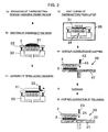
- Figs. 3 (a) to (g) show a flow of a process for producing a workpiece holder for polishing of the present invention.
- the inventors of the present invention searched and studied about the material of workpiece holder body, the material and structure of the holding surface and so forth. As a result, it was found that a workpiece with high flatness and no waviness could be obtained by holding a workpiece by vacuum adsorption on a coating film of thermosetting resin, which is directly coated on a holding surface of a workpiece holder body, and polishing it by a polishing apparatus. Then, they defined various conditions for practically utilizing this finding, and thus accomplished the present invention.
- Fig. 1 represents schematic explanatory views for illustrating the general structure of the workpiece holder for polishing as an example of the present invention.
- Fig. 2 represents explanatory views for illustrating the general structures of a polishing head provided with the workpiece holder for polishing (a), and a polishing apparatus provided with the polishing head (b).
- the polishing apparatus of the present invention is designed-as an apparatus for polishing one surface of a workpiece, for example, a semiconductor wafer, and as shown in Fig. 2 (b), the polishing apparatus 20 consists of a rotating polishing turn table (turning table) 21, a workpiece holder 1 for polishing mounted on a polishing head 10, and a polishing agent feeding nozzle 23.
- a polishing pad 22 is adhered on the upper surface of the polishing turn table 21.
- the polishing turn table 21 is rotated at a predetermined rotation speed by a rotating shaft.
- the workpiece holder 1 for polishing holds a workpiece (wafer) W on its workpiece holding surface 8 by vacuum adsorption or the like, and mounted on the polishing head 10 having the rotation shaft.
- the holder is rotated by the polishing head 10 and simultaneously presses the workpiece W against the polishing pad 22 at a predetermined load.
- a polishing agent 24 is fed from the nozzle 23 at a predetermined flow rate on the polishing pad 22, and then fed between the workpiece W and the polishing pad 22, and thus the workpiece W is polished.
- the workpiece holder 1 for polishing of the present invention is constituted by a workpiece holder body 2 having a workpiece holding surface 8 and multiple perforated holes 4 for vacuum adsorption, and a workpiece holder back plate 5.
- the perforated holes 4 are communicated to a vacuum apparatus not shown in the figure via a space 6 located between the workpiece holder body 2 and the workpiece holder back plate 5, and a vacuum way 7, and the workpiece W is held on the workpiece holding surface 8 upon generation of vacuum.
- the workpiece holding surface 8 of the workpiece holder body 2 is coated with a thermosetting resin coating film 3 which has perforated holes 4.
- the polishing head 10 has a pressurized space 13 in its rotating holder 11, and holds the workpiece holder 1 for polishing airtightly via an elastomer ring 12.
- the pressurized space 13 communicates with an air compressor (now shown) via a pressurization way 14.
- the workpiece holder 1 which holds the workpiece W on the surface of resin coating film 3 of the workpiece holding surface 8 by vacuum adsorption is rotated or oscillated, and at the same time, the back face of the workpiece holder 1 is pressurized with air so as to press the workpiece holder 1 against the polishing pad 22.
- thermosetting resin is charged in a mixing chamber, and sufficiently degassed under vacuum to eliminate air contained in it.
- the workpiece holder body 2 of the workpiece holder 1 for polishing is placed on a resin application jig 30 so that the workpiece holding surface 8 should be the upper side, and after a coating amount adjusting plate 32 is set, the thermosetting resin 31 is poured on the workpiece holding surface 8.
- a bar 33 is slid on the coating amount adjusting plate 32 to scrape excessive resin so that a resin layer having a uniform thickness should be formed.
- the workpiece holder body 2 on which the resin has been applied is placed in an electric heating furnace 35 together with the resin application jig 30, and heating is started so that the whole resin layer 31 should be cured, while heated gas 34 is passed through the perforated holes 4 of the workpiece holder body 2 from below the resin application jig 30.
- the resin 31 in the vicinity of the perforated holes 4 can be preliminarily cured, and then the remainder resin can be cured. In such a case, because the resin in the vicinity of the perforated holes is cured first, the blocking of the perforated holes 4 can more surely be prevented.
- the temperature of the gas 34 for the heat curing may be the same as or higher than the heat curing temperature of the resin. If it is the same as the heat curing temperature of the resin, the heat curing reaction rate of the resin will become a more potent rate-determining factor rather than the viscosity decreasing rate of the resin by heating. Therefore, the resin coating film 3 can be formed without blocking the perforated holes, and thus it is preferred.
- step (e) the workpiece holder body 2 coated with the resin coating film 3 is mounted on a lapping machine 40, and a lapping solution 43 is added dropwise from a nozzle 42, while rotating a turn table 41, to grind the surface of the resin coating film 3 thereby performing surface correction.
- the surface is then sufficiently cleaned in the step (f).
- the workpiece holder body 2 coated with the resin coating film 3 after the lapping correction is mounted on a polishing apparatus 20, and a polishing agent 24 is added dropwise from a nozzle 23, while rotating a turn table 21, to polish the surface of the resin coating film 3 thereby performing surface correction.
- the workpiece holder body 2 can be completed, and a workpiece holder back plate 5 is attached to it to produce a workpiece holder 1 for polishing.
- the workpiece holder 1 for polishing manufactured through the steps described above can be fixed to a polishing head 10, which can then be mounted on a polishing apparatus 20.
- polishing can be performed by holding the workpiece W on the surface of resin coating film 3 of the workpiece holding surface 8 of workpiece holder body 2 by vacuum adsorption, and pressing the workpiece against the rotating polishing pad 22 while adding the polishing agent 24 dropwise.
- the unevenness of adhesion can be eliminated, which is generated in a conventional technique where a resin plate is adhered on a workpiece holding surface of a holder body with an adhesive.
- thermosetting resin used for the present invention can be one selected from epoxy resins, unsaturated polyester resins, urethane resins and phenol resins.
- epoxy resins can sufficiently satisfy the physical properties of the coating film after heat curing required for the present invention, including hardness, mechanical strength, coefficient of linear expansion and so forth.
- thermosetting resin desirably has a viscosity of 10,000 cps or more.
- a resin of such a high viscosity it becomes possible to relatively easily form the perforated holes of a small diameter for holding by vacuum adsorption in the resin coating film after the heat curing.
- thermosetting resin before applying the thermosetting resin to the workpiece holding surface, it is preferably degassed beforehand by kneading under vacuum. If air bubbles remain inside the resin coating film after the heat curing or on its surface, the air bubbles or traces thereof are transferred to the workpiece surface during the polishing of the workpiece. Therefore, before applying the thermosetting resin of a high viscosity to the workpiece holding surface of the workpiece holder, it is desirably degassed by kneading under sufficient vacuum so that the air contained in the resin should be eliminated.
- the resin coating film coating the holding surface of the workpiece holder body desirably has a thickness of 0.5 to 3 mm. Further, the surface of resin coating film is preferably subjected to correction by lapping and then correction by polishing on a polishing turn table of a polishing apparatus.
- the resin coating film has a thickness of 3 mm or less as described above, the rigidity of the workpiece holder body will not be reduced, and hence workpiece polishing can be performed with higher precision.
- a thickness of 0.5 mm or more can provide high flatness.
- a shape of the holding surface of the holder body can be formed with higher precision, and use of such a workpiece holder enables workpiece polishing affording high flatness.
- the perforated holes preferably have a diameter of 0.4 to 0.8 mm
- the material of the workpiece holder body desirably has a coefficient of linear thermal expansion of 1 x 10 -5 /°C or less
- the material of the workpiece holder body is preferably composed of a sintered body (ceramics) of silicon carbide (SiC).
- the perforated holes have a diameter of 0.4 mm or more as defined above, the possibility of the blocking of the holes with the resin is eliminated when the resin coating film is formed with the thermosetting resin on the holding surface of the holder body. On the other hand, if the diameter is 0.8 mm or less, transfer of traces of the holes during the polishing of the workpiece due to an unduly large diameter can be prevented.
- the workpiece holder body by forming the workpiece holder body with a material of a low coefficient of linear thermal expansion, difference of the thermal deformation degrees of the workpiece holder body between during the polishing of the holding surface of the workpiece holder body on a polishing turn table of a polishing apparatus and during the polishing of a workpiece can be reduced, and therefore the shape of the holding surface of the workpiece holder of high precision can be maintained.
- workpiece polishing providing high flatness can be realized.
- silicon carbide is preferably used as a material of a particularly low coefficient of thermal expansion.
- a workpiece holder was produced under the same conditions as in Example 1 except that the thickness of the resin coating film formed on the holding surface of the workpiece holder body was set to be 3 mm, and polishing of the workpiece was performed under the same conditions.
- a workpiece holder body was produced under the same conditions as in Example 1 except that the diameter of the holes for vacuum adsorption of the workpiece holder body was set to be 0.3 mm, 0.8 mm or 1.2 mm, and polishing of the workpiece was performed under the same conditions.
- the diameter was 0.3 mm, some of the holes might be blocked, and require processing for correction.
- the diameter was 0.8 mm, there might be observed slight transfer of the holes for vacuum adsorption on the workpiece surface observed by a magic mirror after the polishing.
- the diameter was 1.2 mm, there was clearly observed transfer of the holes for vacuum adsorption. Therefore, it was confirmed that the diameter was preferably 0.4 to 0.8 mm.
- thermosetting epoxy resin to be applied to the holding surface of the workpiece holder body was not degassed by kneading under vacuum before use, and polishing of the workpiece was performed under the same conditions.
- Example 2 While a result similar to that of Example 1 was obtained for the most cases, there might be generated waviness on the workpiece surface observed by a magic mirror after the polishing, which was considered to be caused by transfer of air bubbles in the resin coating film.
- a workpiece holder body was produced under the same conditions as in Example 1 except that stainless steel (coefficient of linear thermal expansion: 12 x 10 -6 /°C) or alumina (ceramics, coefficient of linear thermal expansion: 7 x 10 -6 /°C) was used as the material of the workpiece holder body, and polishing of the workpiece was performed under the same conditions.
- the flatness of back side reference of the workpiece, SBIRmax was 0.3 ⁇ m when stainless steel was used, and 0.25 ⁇ m when alumina was used.
- a workpiece holder body was produced under the same conditions as in Example 1 except that one of three kinds of porous epoxy resin plates each having a thickness of 1 mm, 3 mm or 5 mm was adhered to the holding surface of the workpiece holder body with an epoxy resin adhesive, and polishing of the workpiece was performed under the same conditions.
- the flatness of back side reference of the workpiece, SBIRmax was gradually degraded as the thickness of the resin plate became thicker. That is, it was 0.40 ⁇ m for the thickness of 1 mm, 0.50 ⁇ m for the thickness of 3 mm, and 0.70 ⁇ m for the thickness of 5 mm.
- the waviness on the workpiece surface in this case, this refers to the transfer of unevenness of adhesion between the resin plate and the workpiece holder body) observed by a magic mirror became larger as the resin plate became thinner.
- the obtained polished workpieces were defective even considering both of the flatness and the waviness.
Landscapes
- Engineering & Computer Science (AREA)
- Mechanical Engineering (AREA)
- Finish Polishing, Edge Sharpening, And Grinding By Specific Grinding Devices (AREA)
- Jigs For Machine Tools (AREA)
- Constituent Portions Of Griding Lathes, Driving, Sensing And Control (AREA)
Applications Claiming Priority (3)
| Application Number | Priority Date | Filing Date | Title |
|---|---|---|---|
| JP31012198 | 1998-10-30 | ||
| JP31012198 | 1998-10-30 | ||
| PCT/JP1999/005852 WO2000025981A1 (en) | 1998-10-30 | 1999-10-22 | Unpolished work holding board and production method thereof and work polishing method and device |
Publications (2)
| Publication Number | Publication Date |
|---|---|
| EP1120193A1 true EP1120193A1 (de) | 2001-08-01 |
| EP1120193A4 EP1120193A4 (de) | 2002-07-24 |
Family
ID=18001438
Family Applications (1)
| Application Number | Title | Priority Date | Filing Date |
|---|---|---|---|
| EP99949378A Withdrawn EP1120193A4 (de) | 1998-10-30 | 1999-10-22 | Unpolierte werkstück haltefläche und deren herstellungsverfahren, verfahren und poliervorrichtung |
Country Status (5)
| Country | Link |
|---|---|
| US (1) | US6386957B1 (de) |
| EP (1) | EP1120193A4 (de) |
| KR (1) | KR100668161B1 (de) |
| TW (1) | TW425627B (de) |
| WO (1) | WO2000025981A1 (de) |
Families Citing this family (10)
| Publication number | Priority date | Publication date | Assignee | Title |
|---|---|---|---|---|
| WO2001056742A1 (en) * | 2000-01-31 | 2001-08-09 | Shin-Etsu Handotai Co., Ltd. | Polishing device and method |
| CN1312740C (zh) * | 2001-09-28 | 2007-04-25 | 信越半导体株式会社 | 用于研磨的工件保持盘及工件研磨装置及研磨方法 |
| DE10235482B3 (de) * | 2002-08-02 | 2004-01-22 | Süss Microtec Lithography Gmbh | Vorrichtung zum Fixieren dünner und flexibler Substrate |
| US7008309B2 (en) * | 2003-05-30 | 2006-03-07 | Strasbaugh | Back pressure control system for CMP and wafer polishing |
| US7033252B2 (en) | 2004-03-05 | 2006-04-25 | Strasbaugh | Wafer carrier with pressurized membrane and retaining ring actuator |
| JP4177796B2 (ja) * | 2004-07-30 | 2008-11-05 | エスペック株式会社 | 冷却装置 |
| JP2013004928A (ja) * | 2011-06-21 | 2013-01-07 | Shin Etsu Handotai Co Ltd | 研磨ヘッド、研磨装置及びワークの研磨方法 |
| KR101357988B1 (ko) | 2012-02-11 | 2014-02-05 | 이인영 | 수지코팅막 성형장치의 진공 흡입에 의한 코팅막 안정화 기구 |
| JP6965305B2 (ja) * | 2019-04-11 | 2021-11-10 | 信越半導体株式会社 | 両面研磨装置 |
| CN111468371B (zh) * | 2020-03-31 | 2022-07-08 | 中国建筑材料科学研究总院有限公司 | 防护膜的制备方法及其装置 |
Family Cites Families (12)
| Publication number | Priority date | Publication date | Assignee | Title |
|---|---|---|---|---|
| JPS52155494A (en) | 1976-06-21 | 1977-12-23 | Nippon Telegr & Teleph Corp <Ntt> | Process for w orking parallel plane of wafer |
| US4333743A (en) * | 1977-10-25 | 1982-06-08 | Nojimagumi Co., Ltd. | Sand-blasting abrasive materials and method of producing the same |
| JPS6373625A (ja) * | 1986-09-17 | 1988-04-04 | Shin Etsu Handotai Co Ltd | 半導体ウエ−ハマウンテイング用樹脂薄膜層の形成方法 |
| JPS63259326A (ja) | 1987-04-15 | 1988-10-26 | Sanyo Electric Co Ltd | 加熱調理器 |
| US4901268A (en) * | 1988-08-19 | 1990-02-13 | General Electric Company | Multiple function data processor |
| DE69316849T2 (de) * | 1992-11-27 | 1998-09-10 | Ebara Corp., Tokio/Tokyo | Verfahren und Gerät zum Polieren eines Werkstückes |
| US5626512A (en) * | 1995-05-04 | 1997-05-06 | Minnesota Mining And Manufacturing Company | Scouring articles and process for the manufacture of same |
| JP3072962B2 (ja) * | 1995-11-30 | 2000-08-07 | ロデール・ニッタ株式会社 | 研磨のための被加工物の保持具及びその製法 |
| KR100485002B1 (ko) * | 1996-02-16 | 2005-08-29 | 가부시키가이샤 에바라 세이사꾸쇼 | 작업물폴리싱장치및방법 |
| JPH10156710A (ja) * | 1996-11-27 | 1998-06-16 | Shin Etsu Handotai Co Ltd | 薄板の研磨方法および研磨装置 |
| JPH11226865A (ja) * | 1997-12-11 | 1999-08-24 | Speedfam Co Ltd | キャリア及びcmp装置 |
| JPH11243135A (ja) | 1998-02-26 | 1999-09-07 | Kyocera Corp | 真空吸着盤 |
-
1999
- 1999-10-22 WO PCT/JP1999/005852 patent/WO2000025981A1/ja not_active Ceased
- 1999-10-22 KR KR1020007007314A patent/KR100668161B1/ko not_active Expired - Fee Related
- 1999-10-22 EP EP99949378A patent/EP1120193A4/de not_active Withdrawn
- 1999-10-22 US US09/581,707 patent/US6386957B1/en not_active Expired - Fee Related
- 1999-10-27 TW TW088118584A patent/TW425627B/zh not_active IP Right Cessation
Non-Patent Citations (2)
| Title |
|---|
| No further relevant documents disclosed * |
| See also references of WO0025981A1 * |
Also Published As
| Publication number | Publication date |
|---|---|
| WO2000025981A1 (en) | 2000-05-11 |
| KR20010024819A (ko) | 2001-03-26 |
| US6386957B1 (en) | 2002-05-14 |
| TW425627B (en) | 2001-03-11 |
| EP1120193A4 (de) | 2002-07-24 |
| KR100668161B1 (ko) | 2007-01-11 |
Similar Documents
| Publication | Publication Date | Title |
|---|---|---|
| US6764392B2 (en) | Wafer polishing method and wafer polishing device | |
| EP1437767A1 (de) | Halteplatte für fräsarbeiten, arbeitsfräseinrichtung und fräsverfahren | |
| US6402594B1 (en) | Polishing method for wafer and holding plate | |
| JPH09270401A (ja) | 半導体ウェーハの研磨方法 | |
| US6386957B1 (en) | Workpiece holder for polishing, method for producing the same, method for polishing workpiece, and polishing apparatus | |
| JPH11111653A (ja) | 半導体ウェーハの製造方法 | |
| EP0860238A2 (de) | Poliervorrichtung | |
| US6422922B1 (en) | Workpiece holder for polishing, apparatus for polishing workpiece and method for polishing workpiece | |
| US6769966B2 (en) | Workpiece holder for polishing, polishing apparatus and polishing method | |
| JPH1174242A (ja) | 半導体装置の製造方法 | |
| JPH06208980A (ja) | 研磨装置 | |
| JP2001025957A (ja) | Cmpコンディショナ及びその製造方法 | |
| EP0845329B1 (de) | Verfahren und Vorrichtung zum Polieren einer dünnen Platte | |
| JP2000198069A (ja) | 研磨用ワ―ク保持盤およびその製造方法ならびにワ―クの研磨方法および研磨装置 | |
| JPH1158232A (ja) | ドレッシング工具及びその製造方法 | |
| JP2002217145A (ja) | 研磨装置用チャック | |
| JPH11333703A (ja) | ポリッシング加工機 | |
| JP2003103457A (ja) | 研磨用ワーク保持盤及びワークの研磨装置及び研磨方法 | |
| JP3940623B2 (ja) | ウェーハ研磨治具とその製造方法及びこれを用いたウェーハ研磨装置 | |
| JP2001341064A (ja) | 研磨用ワーク保持盤および研磨装置ならびに研磨方法 | |
| KR100583279B1 (ko) | 반도체 웨이퍼 연마 장치에 사용하는 탄성 지지대 | |
| JPH10175160A (ja) | 研磨方法及び研磨装置 | |
| JPH05293747A (ja) | 半導体基板の研磨加工方法およびその装置 | |
| JPH11291161A (ja) | 研磨方法 | |
| JPH07263386A (ja) | 半導体ウェーハの表面基準研磨装置 |
Legal Events
| Date | Code | Title | Description |
|---|---|---|---|
| PUAI | Public reference made under article 153(3) epc to a published international application that has entered the european phase |
Free format text: ORIGINAL CODE: 0009012 |
|
| 17P | Request for examination filed |
Effective date: 20000705 |
|
| AK | Designated contracting states |
Kind code of ref document: A1 Designated state(s): AT BE CH CY DE DK ES FI FR GB GR IE IT LI LU MC NL PT SE |
|
| A4 | Supplementary search report drawn up and despatched |
Effective date: 20020612 |
|
| AK | Designated contracting states |
Kind code of ref document: A4 Designated state(s): DE GB IT |
|
| RBV | Designated contracting states (corrected) |
Designated state(s): DE GB IT |
|
| STAA | Information on the status of an ep patent application or granted ep patent |
Free format text: STATUS: THE APPLICATION IS DEEMED TO BE WITHDRAWN |
|
| 18D | Application deemed to be withdrawn |
Effective date: 20060103 |