EP1120612A1 - Kältekreislauf - Google Patents
Kältekreislauf Download PDFInfo
- Publication number
- EP1120612A1 EP1120612A1 EP98947779A EP98947779A EP1120612A1 EP 1120612 A1 EP1120612 A1 EP 1120612A1 EP 98947779 A EP98947779 A EP 98947779A EP 98947779 A EP98947779 A EP 98947779A EP 1120612 A1 EP1120612 A1 EP 1120612A1
- Authority
- EP
- European Patent Office
- Prior art keywords
- pressure
- safety
- low
- compressor
- freezing cycle
- Prior art date
- Legal status (The legal status is an assumption and is not a legal conclusion. Google has not performed a legal analysis and makes no representation as to the accuracy of the status listed.)
- Withdrawn
Links
Images


Classifications
-
- F—MECHANICAL ENGINEERING; LIGHTING; HEATING; WEAPONS; BLASTING
- F04—POSITIVE - DISPLACEMENT MACHINES FOR LIQUIDS; PUMPS FOR LIQUIDS OR ELASTIC FLUIDS
- F04C—ROTARY-PISTON, OR OSCILLATING-PISTON, POSITIVE-DISPLACEMENT MACHINES FOR LIQUIDS; ROTARY-PISTON, OR OSCILLATING-PISTON, POSITIVE-DISPLACEMENT PUMPS
- F04C28/00—Control of, monitoring of, or safety arrangements for, pumps or pumping installations specially adapted for elastic fluids
- F04C28/28—Safety arrangements; Monitoring
-
- F—MECHANICAL ENGINEERING; LIGHTING; HEATING; WEAPONS; BLASTING
- F04—POSITIVE - DISPLACEMENT MACHINES FOR LIQUIDS; PUMPS FOR LIQUIDS OR ELASTIC FLUIDS
- F04C—ROTARY-PISTON, OR OSCILLATING-PISTON, POSITIVE-DISPLACEMENT MACHINES FOR LIQUIDS; ROTARY-PISTON, OR OSCILLATING-PISTON, POSITIVE-DISPLACEMENT PUMPS
- F04C28/00—Control of, monitoring of, or safety arrangements for, pumps or pumping installations specially adapted for elastic fluids
- F04C28/06—Control of, monitoring of, or safety arrangements for, pumps or pumping installations specially adapted for elastic fluids specially adapted for stopping, starting, idling or no-load operation
-
- F—MECHANICAL ENGINEERING; LIGHTING; HEATING; WEAPONS; BLASTING
- F25—REFRIGERATION OR COOLING; COMBINED HEATING AND REFRIGERATION SYSTEMS; HEAT PUMP SYSTEMS; MANUFACTURE OR STORAGE OF ICE; LIQUEFACTION SOLIDIFICATION OF GASES
- F25B—REFRIGERATION MACHINES, PLANTS OR SYSTEMS; COMBINED HEATING AND REFRIGERATION SYSTEMS; HEAT PUMP SYSTEMS
- F25B1/00—Compression machines, plants or systems with non-reversible cycle
- F25B1/04—Compression machines, plants or systems with non-reversible cycle with compressor of rotary type
- F25B1/047—Compression machines, plants or systems with non-reversible cycle with compressor of rotary type of screw type
-
- F—MECHANICAL ENGINEERING; LIGHTING; HEATING; WEAPONS; BLASTING
- F25—REFRIGERATION OR COOLING; COMBINED HEATING AND REFRIGERATION SYSTEMS; HEAT PUMP SYSTEMS; MANUFACTURE OR STORAGE OF ICE; LIQUEFACTION SOLIDIFICATION OF GASES
- F25B—REFRIGERATION MACHINES, PLANTS OR SYSTEMS; COMBINED HEATING AND REFRIGERATION SYSTEMS; HEAT PUMP SYSTEMS
- F25B49/00—Arrangement or mounting of control or safety devices
- F25B49/005—Arrangement or mounting of control or safety devices of safety devices
-
- F—MECHANICAL ENGINEERING; LIGHTING; HEATING; WEAPONS; BLASTING
- F25—REFRIGERATION OR COOLING; COMBINED HEATING AND REFRIGERATION SYSTEMS; HEAT PUMP SYSTEMS; MANUFACTURE OR STORAGE OF ICE; LIQUEFACTION SOLIDIFICATION OF GASES
- F25B—REFRIGERATION MACHINES, PLANTS OR SYSTEMS; COMBINED HEATING AND REFRIGERATION SYSTEMS; HEAT PUMP SYSTEMS
- F25B49/00—Arrangement or mounting of control or safety devices
- F25B49/02—Arrangement or mounting of control or safety devices for compression type machines, plants or systems
- F25B49/025—Motor control arrangements
-
- F—MECHANICAL ENGINEERING; LIGHTING; HEATING; WEAPONS; BLASTING
- F25—REFRIGERATION OR COOLING; COMBINED HEATING AND REFRIGERATION SYSTEMS; HEAT PUMP SYSTEMS; MANUFACTURE OR STORAGE OF ICE; LIQUEFACTION SOLIDIFICATION OF GASES
- F25B—REFRIGERATION MACHINES, PLANTS OR SYSTEMS; COMBINED HEATING AND REFRIGERATION SYSTEMS; HEAT PUMP SYSTEMS
- F25B9/00—Compression machines, plants or systems, in which the refrigerant is air or other gas of low boiling point
- F25B9/002—Compression machines, plants or systems, in which the refrigerant is air or other gas of low boiling point characterised by the refrigerant
- F25B9/008—Compression machines, plants or systems, in which the refrigerant is air or other gas of low boiling point characterised by the refrigerant the refrigerant being carbon dioxide
-
- F—MECHANICAL ENGINEERING; LIGHTING; HEATING; WEAPONS; BLASTING
- F25—REFRIGERATION OR COOLING; COMBINED HEATING AND REFRIGERATION SYSTEMS; HEAT PUMP SYSTEMS; MANUFACTURE OR STORAGE OF ICE; LIQUEFACTION SOLIDIFICATION OF GASES
- F25B—REFRIGERATION MACHINES, PLANTS OR SYSTEMS; COMBINED HEATING AND REFRIGERATION SYSTEMS; HEAT PUMP SYSTEMS
- F25B2309/00—Gas cycle refrigeration machines
- F25B2309/06—Compression machines, plants or systems characterised by the refrigerant being carbon dioxide
- F25B2309/061—Compression machines, plants or systems characterised by the refrigerant being carbon dioxide with cycle highest pressure above the supercritical pressure
-
- F—MECHANICAL ENGINEERING; LIGHTING; HEATING; WEAPONS; BLASTING
- F25—REFRIGERATION OR COOLING; COMBINED HEATING AND REFRIGERATION SYSTEMS; HEAT PUMP SYSTEMS; MANUFACTURE OR STORAGE OF ICE; LIQUEFACTION SOLIDIFICATION OF GASES
- F25B—REFRIGERATION MACHINES, PLANTS OR SYSTEMS; COMBINED HEATING AND REFRIGERATION SYSTEMS; HEAT PUMP SYSTEMS
- F25B2400/00—Component parts or details not otherwise provided for in this subclass
- F25B2400/13—Economisers
-
- F—MECHANICAL ENGINEERING; LIGHTING; HEATING; WEAPONS; BLASTING
- F25—REFRIGERATION OR COOLING; COMBINED HEATING AND REFRIGERATION SYSTEMS; HEAT PUMP SYSTEMS; MANUFACTURE OR STORAGE OF ICE; LIQUEFACTION SOLIDIFICATION OF GASES
- F25B—REFRIGERATION MACHINES, PLANTS OR SYSTEMS; COMBINED HEATING AND REFRIGERATION SYSTEMS; HEAT PUMP SYSTEMS
- F25B2600/00—Control issues
- F25B2600/02—Compressor control
- F25B2600/025—Compressor control by controlling speed
-
- F—MECHANICAL ENGINEERING; LIGHTING; HEATING; WEAPONS; BLASTING
- F25—REFRIGERATION OR COOLING; COMBINED HEATING AND REFRIGERATION SYSTEMS; HEAT PUMP SYSTEMS; MANUFACTURE OR STORAGE OF ICE; LIQUEFACTION SOLIDIFICATION OF GASES
- F25B—REFRIGERATION MACHINES, PLANTS OR SYSTEMS; COMBINED HEATING AND REFRIGERATION SYSTEMS; HEAT PUMP SYSTEMS
- F25B2700/00—Sensing or detecting of parameters; Sensors therefor
- F25B2700/19—Pressures
- F25B2700/193—Pressures of the compressor
- F25B2700/1931—Discharge pressures
-
- Y—GENERAL TAGGING OF NEW TECHNOLOGICAL DEVELOPMENTS; GENERAL TAGGING OF CROSS-SECTIONAL TECHNOLOGIES SPANNING OVER SEVERAL SECTIONS OF THE IPC; TECHNICAL SUBJECTS COVERED BY FORMER USPC CROSS-REFERENCE ART COLLECTIONS [XRACs] AND DIGESTS
- Y02—TECHNOLOGIES OR APPLICATIONS FOR MITIGATION OR ADAPTATION AGAINST CLIMATE CHANGE
- Y02B—CLIMATE CHANGE MITIGATION TECHNOLOGIES RELATED TO BUILDINGS, e.g. HOUSING, HOUSE APPLIANCES OR RELATED END-USER APPLICATIONS
- Y02B40/00—Technologies aiming at improving the efficiency of home appliances, e.g. induction cooking or efficient technologies for refrigerators, freezers or dish washers
Definitions
- the present invention relates to a freezing cycle used in an air-conditioning system for vehicles, and in more specific terms, it relates to a freezing cycle having a safety device that protects components constituting the freezing cycle from damage caused by an abnormally high pressure when carbon dioxide is used as a coolant.
- Examples of freezing cycles in the prior art include the one disclosed in Japanese Unexamined Patent Publication No. H 7-25231.
- This freezing cycle which uses a freon coolant, comprises, at least, a compressor which compresses the coolant, and a condenser, an expansion valve and an evaporator which are connected to the compressor in series.
- the freezing cycle is further provided with an auxiliary coolant passage set parallel to the expansion valve and a valve for opening/closing the auxiliary coolant passage, and the auxiliary coolant passage is opened when the low-level pressure becomes equal to or lower than a specific value.
- freezing cycles provided with a device for turning off the cycle by judging that the quantity of the coolant is not sufficient or that the load is too low due to a low external air temperature when the high pressure becomes equal to or lower than a specific value, i.e., freezing cycles provided with a low-level cut switch.
- Other safety mechanisms that may be provided in freezing cycles include a device that stops the operation of the compressor when the high pressure becomes equal to or higher than a specific value, a device that stops the compressor when the outlet temperature at the compressor becomes equal to or higher than a specific value, a device that discharges the high-pressure coolant into the atmosphere when the high pressure becomes equal to or higher than a specific value and a fusible plug that allows the coolant to be discharged into the atmosphere when the coolant temperature becomes equal to or higher than a specific value.
- the high level side pressure reacts more sharply to fluctuations in the load compared to a freon coolant which becomes condensed on the high pressure side.
- the likelihood of the high pressure in a reciprocal critical cycle reaching the vicinity of the maximum normal operating pressure is much higher than the likelihood of that occurring in the cycles currently in use. If a high-pressure cut switch is employed in a reciprocal critical cycle, a problem will occur in that the high-pressure cut switch will be activated too frequently.
- the high pressure in the conventional cycle is approximately 1.2 ⁇ 3 MPa, with the setting for the high pressure cut switch at approximately 3 MPa.
- the balance pressure between the high-pressure side and the low-pressure side in the reciprocal critical cycle left in hot daylight becomes as high as approximately 10 MPa. While it is desirable to minimize the coolant volume on the high-pressure side in order to prevent the balance pressure from rising, there is a problem in that minimizing the coolant volume on the high-pressure side would increase the passage resistance on the high-pressure side to result in a large pressure loss.
- an object of the present invention is to provide a freezing cycle having a means for safety that is most suited for application in a freezing cycle using carbon dioxide as a coolant.
- the freezing cycle according to the present invention which uses carbon dioxide for a coolant and comprises, at least, a compressor that compresses the coolant to a level in a super critical range, a radiator that cools the compressed coolant, an expansion device that lowers the pressure of the cooled coolant down to a gas /liquid mixed range and an evaporator that evaporates a liquid-phase coolant generated by the expansion device, having a high-pressure line extending from the outlet side of the compressor to the intake side of the expansion device and a low-pressure line extending from the outlet side of the expansion valve to the intake side of the compressor, is further provided with a first means for safety that communicates between the high-pressure line and the low-pressure line when the pressure in the high-pressure line becomes equal to or higher than a first specific pressure, a second means for safety that communicates between the high-pressure line and the atmosphere when the pressure in the high-pressure line becomes equal to or higher than a second specific pressure higher than the first specific pressure, a third means for safety that stops the drive of the compressor
- the first means for safety with a high-pressure relief valve that releases the high pressure toward the low-pressure side when the high pressure reaches the first specific pressure.
- the high-pressure relief valve should communicate between the area near the outlet side of the compressor and the area in the vicinity of the intake side of the compressor.
- the third means for safety which is provided to protect the compressor from any damage that may otherwise occur when the coolant leaks, stops the compressor when the pressure in the high-pressure line becomes equal to or lower than the third specific pressure. More specifically, it is provided with a pressure sensor that detects the high pressure, and stops the means for driving the compressor when the level of the pressure detected by the pressure sensor is equal to or lower than the third specific pressure (by shutting down the electromagnetic clutch linking the compressor to the engine, stopping the motor, etc. ).
- the fourth means for safety with a low-pressure rupture disk which ruptures when the pressure in the low-pressure line is at the fourth specific pressure level higher than the third specific pressure. Since the pressure in the low-pressure line rises as the temperature increases in the event of a fire occurring in the engine room, the low-pressure rupture disk will fulfill a function similar to that of a fusible plug in the prior art. In addition, since it achieves a pressure-dependent function, it prevents damage occurring when the coolant is charged to an excessive degree by mistake. Furthermore, it is capable of tolerating an abnormal increase in the balance pressure occurring when the vehicle is left in the hot sun.
- a safety device comprising a relief valve constituting the first means for safety, a high-pressure rupture disk constituting the second means for safety and a low-pressure rupture disk constituting the fourth means for safety provided as an integrated unit, may be created to be installed as an integrated part of the compressor.
- a splash-preventing film should be formed over the areas where rupture may occur due to a high pressure, such as the header tank of the radiator, the accumulator main unit, the hose caulking metal fixtures and the evaporator tank.
- PET polyethylene terephthalate
- PVB polyvinyl butyryl
- a laminated sheet constituted by enclosing a fibrous substance or a fibrous sheet constituted of resin or metal in the base member may be used instead.
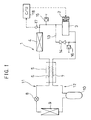
- a radiator (gas cooler) 4 that cools the coolant that has been compressed by the compressor 3 to a level in a super critical range is connected to the outlet side of the compressor 3. Since the coolant is in the super critical range, the coolant remains a gas-phase coolant even when it has been cooled in the gas cooler 4 and, thus, the gas-phase coolant flows into a first heat exchanging unit 6 constituting an internal heat exchanger 5 at the next stage.
- the gas-phase coolant flowing through the first heat exchanging unit 6 in the internal heat exchanger 5 becomes further cooled through a heat exchange with the low-pressure, low-temperature gas-phase coolant passing through a second heat exchanging unit 7 of the internal heat exchanger 5, which is to be detailed below, to be delivered to an expansion device 8.
- the expansion device 8 lowers the pressure of the high-pressure gas-phase coolant down to a gas/liquid mixed range, and is constituted as a type of automatic expansion valve.
- the coolant in the gas/liquid mixed state resulting from the pressure reduction at the expansion device 8 absorbs heat at an evaporator 9 provided on the downstream side relative to the expansion device 8 and evaporates to become a gas-phase coolant.
- An accumulator 10 is provided on the downstream side relative to the evaporator 9.
- the quantity of the coolant flowing through the entire freezing cycle is adjusted and gas/liquid separation is achieved.
- the coolant having undergone the gas/liquid separation is then delivered to the second heat exchanging unit 7 of the internal heat exchanger 5 mentioned earlier.
- the coolant delivered from the accumulator 10 to the second heat exchanging unit 7 then undergoes heat exchange with the gas-phase coolant passing through the first heat exchanging unit 6 to become heated and is taken into the compressor 3.
- the freezing cycle 1 which absorbs heat at the evaporator 9 and radiates heat at the gas cooler 4, is achieved.
- the range extending from the outlet side of the compressor 3 to the intake side of the expansion device 8 is defined as a high-pressure line 11 and the range extending from the outlet side of the expansion device 8 to the intake side of the compressor 3 is defined as a low-pressure line 12.
- the pressure tolerance of the gas cooler 4 constituted of an aluminum material is 20 MPa at the most under normal circumstances due to such factors as the heat exchanging rate, the weight and the cost that must be taken into consideration, and thus, it is necessary to take safety measures to protect the freezing cycle.
- a bypass passage 13 communicating between the high-pressure line 11 in the vicinity of the outlet side of the compressor 3 and the low-pressure line 12 in the vicinity of the intake side of the compressor 3 and a relief valve 14 located at the bypass pixels 13 which releases the high-pressure coolant into the low-pressure line 12 when the high pressure in the high-pressure line 11 reaches a level equal to or higher than a first specific value (e.g., 16 ⁇ 18 MPa) are provided to constitute a first means for safety.
- a first specific value e.g., 16 ⁇ 18 MPa
- the high-pressure side of the bypass passage 13 is set in the vicinity of the outlet side of the compressor 3 in this structure by taking into consideration the pressure loss in the high-pressure line 11. In other words, it is necessary to minimize the high-pressure side coolant volume in the high-pressure line 11 in order to prevent the balance pressure from rising when the vehicle is left in the hot sun. Thus, a certain degree of pressure difference is bound to occur due to the pressure loss between the vicinity of the outlet side of the compressor 3 and the vicinity of the intake side of the expansion device 8. Accordingly, in order to eliminate problems occurring as a result of an increase in the high pressure, the high-pressure side of the bypass passage 13 should be set as close as possible to the outlet side of the compressor 3.
- a rupture disk 15 which ruptures at a second specific pressure (e.g., 18 ⁇ 20 MPa) higher than the first specific pressure is provided as a second means for safety.
- a second specific pressure e.g. 18 ⁇ 20 MPa
- the rupture disk 15 ruptures to open communication between the high-pressure line 11 and the atmosphere, thereby discharging the coolant in the high-pressure line 11 into the atmosphere and thus protecting the various devices in the freezing cycle 1 from an abnormally high pressure.
- a high pressure detection sensor 17 constituting a third means for safety is provided in the high-pressure line 11, and the high pressure detected by the high pressure detection sensor 17 is input to a control unit 18 where it is compared against a third specific pressure (which may be set at, for instance, 2 ⁇ 4MPa). If it is decided that the detected high pressure is equal to or lower than the third specific pressure, the power supply to the electromagnetic clutch 2 is stopped to disconnect the compressor 3 from the engine (not shown) thereby stopping the drive of the compressor 3. Thus, since a reduction in the quantity of coolant resulting from a coolant leak or the like can be identified as the cause of the high pressure becoming lowered to a level equal to or lower than the third specific pressure, the compressor 3 is stopped to protect the compressor in such an event.
- a third specific pressure which may be set at, for instance, 2 ⁇ 4MPa
- a rupture disk 16 which ruptures at a fourth specific pressure (approximately 12 ⁇ 13 MPa) higher than the balance pressure (approximately 10 MPa) is provided in the low-pressure line 12 as a fourth means for safety, so that the various devices provided on the low-pressure line 12 are protected by communicating between the low-pressure line 12 and the atmosphere and releasing the coolant whose pressure has risen into the atmosphere.
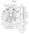
- a safety device 40 achieved by forming the first, second and fourth means for safety as an integrated unit is installed as an integrated part of the compressor 3.
- the safety device 40 is mounted at a rear housing 31 of the compressor 3, with the rear housing 31 having an outlet space 33, which communicates with an outlet hole 32 communicating with a compression space (not shown) of the compressor when an outlet valve 34 is opened, formed therein.
- an intake space 37 communicating with an intake hole 36 which communicates with the compression space is also formed.
- the outlet space 33 communicates with the gas cooler 4 via an outlet hole (not shown) and the intake space 37 communicates with the second heat exchanging unit 7 of the internal heat exchanger 5 via an intake hole (not shown).
- a high-pressure side bypass passage 38a and a low-pressure side bypass passage 38b constituting the bypass passage 13 are provided at the rear housing 31, with the safety device 40 mounted between the high-pressure side bypass passage 38a and the low-pressure side bypass passage 38b.
- the safety device 40 is mounted so as to block off a low-pressure side space 39 formed at one end of the low-pressure side bypass passage 38b, and is provided with a valve seat plate 41 having two through holes 42 and 53 communicating with the low-pressure side space 39.
- a valve seat 44 is formed at one end of the through hole 53 at the valve seat plate 41.
- reference number 43 indicates an O-ring which seals the circumferential edge of the valve seat plate 41.
- a communicating hole 52 communicating between the high-pressure space 51 and the high-pressure side bypass passage 38a and a high-pressure side release hole 53 communicating between the high-pressure space 51 and the atmosphere are formed.
- a low-pressure side release hole 54 communicating with the through hole 42 at the valve seat plate 41 is formed.
- a valve element 45 which closes the through hole 53 when it is seated on the valve seat 44, is provided and the valve element 45 is connected with a bellows 47 via a rod 46.
- the bellows 47 is constituted of a plate portion 47A which is linked to the rod 46 and holds a spring 49 that applies a force to the valve element 45 toward the valve seat via the rod 46 and a retractable bellows portion 47B that defines an internal space 48 into which a gas achieving a specific pressure level is sealed.
- the bellows portion 47B becomes contracted, causing the valve element 45 to depart from the valve seat 44, thereby allowing the high-pressure side bypass passage 38a and the low-pressure side bypass passage 38b to communicate with each other.
- the relief valve 14 functions as the first means for safety.
- the high-pressure side rupture disk 15, which ruptures at the second specific pressure is provided as the second means for safety.
- the high-pressure side rupture disk 15 which is constituted of a disk portion 62 that ruptures at the second specific pressure, a retaining portion 61 that holds the disk portion and a screw portion 63 that secures the retaining portion 61, the disk portion 62 ruptures to set the high-pressure side release hole 53 and the atmosphere in a communicating state when the high pressure in the high-pressure space 51 reaches a level equal to or higher than the second specific pressure.
- the low-pressure side rupture disk 16 which ruptures at the fourth specific pressure is provided as the fourth means for safety.
- the low-pressure side rupture disk 16 which is constituted of a disk portion 66 that ruptures at the fourth specific pressure, a retaining portion 65 that holds the disk portion 66 and a screw portion 67 that secures the retaining portion 65, the disk portion 66 ruptures to set the low-pressure side release hole 54 and the atmosphere in the communicating state when the low-pressure in the low-pressure side space 39 reaches a level equal to or higher than the fourth specific pressure.
- reference number 55 indicates an O-ring that seals the space between the valve housing and the rear housing 31.
- FIG. 3 presents a variation of the embodiment shown in FIG. 2.
- a valve block 71 is provided to be mounted at the rear housing 31.
- a high-pressure side passage 72 that is to communicate with the high-pressure side bypass passage described earlier and a low-pressure side passage 73 to communicate with the low-pressure side bypass passage are formed, with a valve seat 77 formed at an end on the inside of the low-pressure side passage 73.
- a high-pressure side release passage 72a and a low-pressure side release passage 74 are formed at the valve block 71.
- valve block 71 One end of the valve block 71 is blocked off by a diaphragm 79, thereby defining a high-pressure space 75.
- a valve element 76 which blocks off the low-pressure side passage 73 when it is seated on the valve seat 77, is provided, with the valve element 76 linked with the diaphragm 79 via a rod 78.
- the circumferential edge of the diaphragm 79 is clamped and secured by a case 82 defining a rear chamber space 81 located rearward relative to the diaphragm 79 and also by the valve block 71.
- a spring 80 which applies a force to the valve element 76 toward the valve seat 77 via the diaphragm 79 and the rod 78 is provided in the rear chamber space 81.
- a gas at a specific pressure level is sealed into the rear chamber space 81 as in the previous embodiment.
- the high-pressure side rupture disk 15 is provided as in the previous embodiment, whereas the low-pressure side rupture disk 16 is provided at the front end of the low-pressure side release passage 74 as in the previous embodiment.
- a splash-preventing film is formed through coating, spraying or deposition over areas such as the tank portions of the gas cooler 4, the main unit of the accumulator 10, the tank portions at the evaporator 9, the oil separator main unit which is not shown in FIG. 1 but may be provided as necessary and the linking areas, as another means for safety.
- the splash-preventing film shown in FIG. 4(a) is constituted by using as a base member 90 preferably PET (polyethylene terephthalate) or PVB (polyvinyl butyryl), i.e., a resin such as a polyethylene resin, a polypropylene resin, a polyvinyl chloride risen or a polyester resin and then forming an adhesive layer 91 on the surface of the base member 90.
- the splash-preventing film shown in FIG. 4(b) is constituted as a laminated sheet by enclosing a fibrous substance constituted of resin or mental as a reinforcement layer 92 in the base member 90 (between the base members 90a and 90b) constituting the splash-preventing film described above.
- the freezing cycle according to the present invention provided with the first means for safety that leaks high pressure into the low-pressure side when the high pressure reaches a level equal to or higher than the first specific pressure, the second means for safety that releases the high pressure into the atmosphere when the high pressure reaches a level equal to or higher than the second specific pressure, the third means for safety that stops the operation of the compressor when the high pressure reaches a level equal to or lower than the third specific pressure and the fourth means for safety that releases the low-level pressure into the atmosphere when the low-pressure reaches a level equal to or higher than a specific pressure, improves the safety of the freezing cycle using carbon dioxide as the coolant.
- the freezing cycle using carbon dioxide as the coolant as an alternative to a freon coolant can be employed in an air-conditioning system for vehicles with peace of mind.
- the safety level can be further improved.
Landscapes
- Engineering & Computer Science (AREA)
- Mechanical Engineering (AREA)
- General Engineering & Computer Science (AREA)
- Physics & Mathematics (AREA)
- Thermal Sciences (AREA)
- Chemical & Material Sciences (AREA)
- Chemical Kinetics & Catalysis (AREA)
- Safety Valves (AREA)
- Air-Conditioning For Vehicles (AREA)
Applications Claiming Priority (1)
| Application Number | Priority Date | Filing Date | Title |
|---|---|---|---|
| PCT/JP1998/004538 WO2000020808A1 (fr) | 1998-10-08 | 1998-10-08 | Cycle frigorifique |
Publications (2)
| Publication Number | Publication Date |
|---|---|
| EP1120612A1 true EP1120612A1 (de) | 2001-08-01 |
| EP1120612A4 EP1120612A4 (de) | 2002-09-25 |
Family
ID=14209161
Family Applications (1)
| Application Number | Title | Priority Date | Filing Date |
|---|---|---|---|
| EP98947779A Withdrawn EP1120612A4 (de) | 1998-10-08 | 1998-10-08 | Kältekreislauf |
Country Status (3)
| Country | Link |
|---|---|
| US (1) | US6321544B1 (de) |
| EP (1) | EP1120612A4 (de) |
| WO (1) | WO2000020808A1 (de) |
Cited By (3)
| Publication number | Priority date | Publication date | Assignee | Title |
|---|---|---|---|---|
| FR2797036A1 (fr) * | 1999-07-29 | 2001-02-02 | Daimler Chrysler Ag | Procede de fonctionnement d'une installation frigorifique pour vehicule fonctionnant en modes sous-critique et transcritique |
| WO2004016997A1 (en) * | 2002-08-17 | 2004-02-26 | Oxford Magnet Technology | Oil carry-over prevention from helium gas compressor |
| EP1486742A1 (de) * | 2003-06-10 | 2004-12-15 | Sanyo Electric Co., Ltd. | Kältekreislaufgerät |
Families Citing this family (20)
| Publication number | Priority date | Publication date | Assignee | Title |
|---|---|---|---|---|
| JP2000130896A (ja) * | 1998-10-29 | 2000-05-12 | Sanden Corp | 安全装置を備えた空調装置 |
| JP4586221B2 (ja) * | 1999-11-08 | 2010-11-24 | Nok株式会社 | 制御弁 |
| US6302654B1 (en) * | 2000-02-29 | 2001-10-16 | Copeland Corporation | Compressor with control and protection system |
| US20040026071A1 (en) * | 2000-03-16 | 2004-02-12 | Ullrich Hesse | Heat exchanger for a co2 vehicle air conditioner |
| JP2002174471A (ja) * | 2000-12-07 | 2002-06-21 | Zexel Valeo Climate Control Corp | 冷凍サイクル |
| US8463744B2 (en) * | 2001-01-03 | 2013-06-11 | International Business Machines Corporation | Method and system for synchronizing data |
| US6418740B1 (en) * | 2001-02-22 | 2002-07-16 | Scroll Technologies | External high pressure to low pressure valve for scroll compressor |
| JP2002257043A (ja) * | 2001-03-06 | 2002-09-11 | Toyota Industries Corp | 圧縮機 |
| JP3903851B2 (ja) * | 2002-06-11 | 2007-04-11 | 株式会社デンソー | 熱交換器 |
| RU2232358C2 (ru) * | 2002-09-20 | 2004-07-10 | Малахов Анатолий Иванович | Холодильная машина (варианты) |
| JP2004340007A (ja) * | 2003-05-14 | 2004-12-02 | Toyota Industries Corp | 可変容量型圧縮機におけるバイパス装置 |
| US7422422B2 (en) * | 2004-08-24 | 2008-09-09 | Tecumseh Products Company | Compressor assembly with pressure relief valve fittings |
| EP1948927B1 (de) * | 2005-11-09 | 2009-08-05 | ixetic MAC GmbH | Klimakompressor mit differenzdruckbegrenzungseinrichtung |
| JP2007232343A (ja) * | 2006-02-02 | 2007-09-13 | Sanden Corp | 冷凍回路及び圧縮機 |
| DE102012001906B4 (de) * | 2012-01-27 | 2014-06-12 | Dürr Somac GmbH | Verfahren zur Vermeidung und Erkennung von Kältemittelaustritten aus komplexen hydraulischen Systemen |
| JP2014020675A (ja) * | 2012-07-18 | 2014-02-03 | Denso Corp | 電池温調用冷凍サイクル装置 |
| JP6291333B2 (ja) * | 2014-04-22 | 2018-03-14 | 東芝キヤリア株式会社 | 冷凍サイクル装置 |
| JP6805794B2 (ja) * | 2016-07-27 | 2020-12-23 | パナソニック株式会社 | 冷凍サイクル装置 |
| JP2018096652A (ja) * | 2016-12-16 | 2018-06-21 | パナソニックIpマネジメント株式会社 | 冷凍サイクル装置 |
| JP7290030B2 (ja) * | 2019-01-31 | 2023-06-13 | 株式会社デンソー | 熱交換器 |
Family Cites Families (12)
| Publication number | Priority date | Publication date | Assignee | Title |
|---|---|---|---|---|
| US3633380A (en) * | 1969-03-21 | 1972-01-11 | Italo Pellizzetti | Refrigerator system |
| US4718442A (en) * | 1986-02-27 | 1988-01-12 | Helix Technology Corporation | Cryogenic refrigerator compressor with externally adjustable by-pass/relief valve |
| US4711096A (en) * | 1986-03-17 | 1987-12-08 | Krantz Herman F | Leak detection and refrigerant purging system |
| DE3721388C1 (de) * | 1987-06-29 | 1988-12-08 | Sueddeutsche Kuehler Behr | Vorrichtung zur Klimatisierung des Innenraums von Personenkraftwagen |
| NO890076D0 (no) | 1989-01-09 | 1989-01-09 | Sinvent As | Luftkondisjonering. |
| US5141407A (en) * | 1990-10-01 | 1992-08-25 | Copeland Corporation | Scroll machine with overheating protection |
| NO915127D0 (no) | 1991-12-27 | 1991-12-27 | Sinvent As | Kompresjonsanordning med variabelt volum |
| US5408840A (en) * | 1994-04-05 | 1995-04-25 | Talley; Curtis G. | Refrigerant overpressure release recovery system with compressor auto shutdown |
| US5457965A (en) * | 1994-04-11 | 1995-10-17 | Ford Motor Company | Low refrigerant charge detection system |
| DE4427710B4 (de) * | 1994-08-05 | 2005-05-04 | Air Liquide Gmbh | Anordnung zur Gasführung und Drucksteuerung an Kaltvergaseranlagen |
| CH689826A5 (de) * | 1995-05-10 | 1999-12-15 | Daimler Benz Ag | Fahrzeug-Klimaanlage. |
| EP0837291B1 (de) * | 1996-08-22 | 2005-01-12 | Denso Corporation | Kälteanlage des Dampfkompressionstyps |
-
1998
- 1998-10-08 WO PCT/JP1998/004538 patent/WO2000020808A1/ja not_active Ceased
- 1998-10-08 EP EP98947779A patent/EP1120612A4/de not_active Withdrawn
- 1998-10-08 US US09/701,176 patent/US6321544B1/en not_active Expired - Fee Related
Cited By (4)
| Publication number | Priority date | Publication date | Assignee | Title |
|---|---|---|---|---|
| FR2797036A1 (fr) * | 1999-07-29 | 2001-02-02 | Daimler Chrysler Ag | Procede de fonctionnement d'une installation frigorifique pour vehicule fonctionnant en modes sous-critique et transcritique |
| WO2004016997A1 (en) * | 2002-08-17 | 2004-02-26 | Oxford Magnet Technology | Oil carry-over prevention from helium gas compressor |
| EP1486742A1 (de) * | 2003-06-10 | 2004-12-15 | Sanyo Electric Co., Ltd. | Kältekreislaufgerät |
| US7086244B2 (en) | 2003-06-10 | 2006-08-08 | Sanyo Electric Co., Ltd. | Refrigerant cycle apparatus |
Also Published As
| Publication number | Publication date |
|---|---|
| WO2000020808A1 (fr) | 2000-04-13 |
| US6321544B1 (en) | 2001-11-27 |
| EP1120612A4 (de) | 2002-09-25 |
Similar Documents
| Publication | Publication Date | Title |
|---|---|---|
| US6321544B1 (en) | Refrigerating cycle | |
| US6334324B1 (en) | Expansion device | |
| US6210120B1 (en) | Low charge protection vent | |
| EP1530013B1 (de) | Entspannungsventil mit magnetbetätigtem Ablassventil | |
| JPH04177072A (ja) | 空調装置 | |
| EP1014013A1 (de) | Kältekreislauf mit Dampfverdichtung | |
| GB2265448A (en) | Reversible heat pump | |
| US6996998B2 (en) | Refrigerant system pressure control for storage and transportation | |
| US6644066B1 (en) | Method and apparatus to relieve liquid pressure from receiver to condenser when the receiver has filled with liquid due to ambient temperature cycling | |
| US5673563A (en) | Pressure relief apparatus and method of use particularly for a refrigeration system | |
| CN110234944B (zh) | 制冷系统 | |
| US5335511A (en) | Refrigerant release prevention system | |
| US20090235673A1 (en) | Detection of refrigerant release in co2 refrigerant systems | |
| EP1521684B1 (de) | Klimaanlage mit abschaltungsisolierung und entlüftung eines verdampfers unter verwendung eines h-förmigem ventils | |
| JP4047497B2 (ja) | 超臨界蒸気圧縮サイクル装置および逃し弁付き圧力制御弁 | |
| JPWO2000020808A1 (ja) | 冷凍サイクル | |
| JP4063584B2 (ja) | 流出防止装置 | |
| US20250102209A1 (en) | Pressure relief arrangement in refrigerant circuits | |
| KR20040078942A (ko) | 초임계 냉동 사이클 보호장치 | |
| JP4039134B2 (ja) | 冷凍サイクル装置に用いる弁装置 | |
| JPS6050366A (ja) | 冷房サイクル用冷媒の異常状態警報装置 | |
| JPH07301461A (ja) | 冷房サイクル | |
| JPH04251174A (ja) | 空調装置 | |
| JP2004353578A (ja) | 気体圧縮機の保護構造 | |
| JPWO2000031479A1 (ja) | 膨張装置 |
Legal Events
| Date | Code | Title | Description |
|---|---|---|---|
| PUAI | Public reference made under article 153(3) epc to a published international application that has entered the european phase |
Free format text: ORIGINAL CODE: 0009012 |
|
| 17P | Request for examination filed |
Effective date: 20001213 |
|
| AK | Designated contracting states |
Kind code of ref document: A1 Designated state(s): DE FR GB |
|
| A4 | Supplementary search report drawn up and despatched |
Effective date: 20020812 |
|
| AK | Designated contracting states |
Kind code of ref document: A4 Designated state(s): DE FR GB |
|
| STAA | Information on the status of an ep patent application or granted ep patent |
Free format text: STATUS: THE APPLICATION HAS BEEN WITHDRAWN |
|
| 18W | Application withdrawn |
Withdrawal date: 20021001 |