EP1120890A2 - Linearmotor mit hohem Schub und sein Herstellungsverfahren - Google Patents
Linearmotor mit hohem Schub und sein Herstellungsverfahren Download PDFInfo
- Publication number
- EP1120890A2 EP1120890A2 EP01101717A EP01101717A EP1120890A2 EP 1120890 A2 EP1120890 A2 EP 1120890A2 EP 01101717 A EP01101717 A EP 01101717A EP 01101717 A EP01101717 A EP 01101717A EP 1120890 A2 EP1120890 A2 EP 1120890A2
- Authority
- EP
- European Patent Office
- Prior art keywords
- coils
- magnetic member
- slots
- linear motor
- thrust
- Prior art date
- Legal status (The legal status is an assumption and is not a legal conclusion. Google has not performed a legal analysis and makes no representation as to the accuracy of the status listed.)
- Granted
Links
Images





Classifications
-
- H—ELECTRICITY
- H02—GENERATION; CONVERSION OR DISTRIBUTION OF ELECTRIC POWER
- H02K—DYNAMO-ELECTRIC MACHINES
- H02K41/00—Propulsion systems in which a rigid body is moved along a path due to dynamo-electric interaction between the body and a magnetic field travelling along the path
- H02K41/02—Linear motors; Sectional motors
- H02K41/03—Synchronous motors; Motors moving step by step; Reluctance motors
- H02K41/031—Synchronous motors; Motors moving step by step; Reluctance motors of the permanent magnet type
-
- H—ELECTRICITY
- H02—GENERATION; CONVERSION OR DISTRIBUTION OF ELECTRIC POWER
- H02K—DYNAMO-ELECTRIC MACHINES
- H02K41/00—Propulsion systems in which a rigid body is moved along a path due to dynamo-electric interaction between the body and a magnetic field travelling along the path
- H02K41/02—Linear motors; Sectional motors
- H02K41/03—Synchronous motors; Motors moving step by step; Reluctance motors
Definitions
- the present invention relates to a high-thrust linear motor in which armature coils and field magnets are arranged linearly to convert electrical energy supplied by the armature coils directly into linear kinetic energy with high thrust through the field magnets.
- This linear motor that converts electrical energy directly into linear kinetic energy by utilizing repulsive or attractive magnetic force.
- This linear motor for example, has a moving part consisting essentially of an armature winding formed from wound coils (electromagnets) and a stationary part having field magnets (permanent magnets) arranged along a guide.
- the moving part is caused to travel linearly along the guide serving as a stationary-side member by utilizing repulsive or attractive magnetic forces acting between the armature coils and the field magnets, thereby converting electrical energy into linear kinetic energy.
- Linear motors arranged as stated above include two different types, i.e. coreless linear motors having no core in the armature winding, and cored linear motors having a core in the armature winding.
- the coreless armature winding consists only of wound coils and therefore causes minimal variations in travel (cogging) of the moving part due to variations in magnetic reluctance that occur during the travel of the moving part. Further, the coreless armature winding is light in weight because it has no core. Therefore, the coreless armature winding is generally used in small-sized linear motors.
- the cored armature winding can be arranged to provide thrust 2 to 3 times as high as that of coreless linear motors simply by inserting a core (magnetic member) into the hollow portion of an air-core armature winding, which has no core. Therefore, the cored armature winding is usually used in high-thrust linear motors.
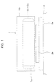
- Figs. 1 and 2 are a front view and a longitudinal sectional view, respectively, showing the arrangement of the cored linear motor.
- This cored linear motor is a three-phase linear motor and has a moving part 1 and a stationary part 2 as shown in Fig. 1.
- the moving part 1 includes a core 1a and a table 1b secured to the upper surface of the core 1a.
- the moving part 1 further includes coils C1, C2 and C3.
- the core la is formed with slots S.
- the coils C1, C2 and C3 are prewound coils and each inserted into two slots S separated by other slots S.
- the core la and the coils C1, C2 and C3 constitute an armature winding.
- the reason why the prewound coils C1, C2 and C3 are inserted into the slots S is to facilitate the assembly.
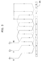
- the coils C1, C2 and C3 are inserted in the following sequence. First, a U-phase coil C1, a W-phase coil C2 and a V-phase coil C3 are inserted into respective pairs of slots S in the order mentioned so as to lie adjacent to the innermost parts of the slots S. Thereafter, a V-phase coil C3 is inserted into two slots S in such a manner as to be superimposed on the U-phase coil C1 and the W-phase coil C2 so that the V-phase coil C3 is different in electrical angle from the phases inserted into the innermost parts of the slots S.
- a U-phase coil C1 is inserted into two slots S in such a manner as to be superimposed on the W-phase coil C2 and the V-phase coil C3 so that the U-phase coil Cl is different in electrical angle from the phases inserted into the innermost parts of the slots S.
- the stationary part 2 is, as shown in Figs. 1 and 2, formed from a yoke 2a and field magnets (permanent magnets) 2b.
- the yoke 2a and the field magnets 2b are disposed to extend linearly so as to face the moving part 1.
- the conventional cored linear motor having the above-described structure suffers from the problem that the relative movement of the magnetic field is not smooth because of the manner of winding the coils. That is, after a U-phase coil C1 and a W-phase coil C2 have been inserted, a V-phase coil C3 is inserted so as to lie over the area between the U-phase coil C1 and the W-phase coil C2. Therefore, there are overlaps between the coils, and this prevents smooth relative movement of the magnetic field.
- An object of the present invention is to provide a high-thrust linear motor in which the amount of winding of coils can be increased in comparison to the weight of the core to obtain increased thrust and the linear motion of the moving part is favorably smooth.
- Another object of the present invention is to provide a method of producing a high-thrust linear motor that allows coils to be wound in such a manner that there is no blank space where no coil is wound in a slot at each end of the core.
- the present invention provides a high-thrust linear motor including a magnetic member having a plurality of slots formed in series in an axial direction thereof.
- the slots extend from both sides of the magnetic member in opposite directions intersecting the axial direction in corresponding relation to each other.
- Coils are wound in respective pairs of slots on both sides of the magnetic member.
- Field magnets extend in the axial direction at both sides of the magnetic member so as to face an effective conductor portion (a portion contributing to the generation of thrust) of each of the coils.
- Each field magnet has a plurality of pairs of magnetic poles magnetized in the axial direction.
- the high-thrust linear motor according to the present invention has the above-described matters as essential constituent elements. However, the following matters may be added to the constituent elements:
- the arrangement may be such that the coils have a plurality of phases and are wound in respective pairs of slots in the magnetic member in such a manner that each pair of adjacent phases are different in electrical angle from each other.
- the high-thrust linear motor according to the present invention may further include a cover member for covering the magnetic member and the coils approximately entirely, exclusive of effective conductor portions of the magnetic member and the coils.
- the cover member covers the armature having the coils wound on approximately the entire area of the magnetic member, and this cover member is secured to a table or other moving member, whereby the armature is prevented from directly contacting the table or other moving member, and the armature can be surely secured to the table or the like through the cover member.
- the above-described arrangement facilitates the operation of securing the magnetic member and the coils to the cover member.
- the connecting members may be formed from a material having high thermal conductivity and disposed in contact with or close proximity to the magnetic member.
- the connecting members act as a radiator, whereby heat generated from the coils can be dissipated to the outside without storing it in the magnetic member. Accordingly, it is possible to prevent reduction of thrust as occurs when the magnetic member is heated.
- a metal for example, aluminum, is preferably used as a material having high thermal conductivity.
- a non-magnetic material may be filled in the space between the magnetic member and the coils on the one hand and the cover member on the other.
- the magnetic member, the coils and the cover member are integrated in close contact with each other. Therefore, none of the magnetic member, the coils and the cover member will be deformed when the assembly of these members moves linearly or stops. Accordingly, the assembly of the magnetic member, the coils and the cover member is suitable for use as a moving part.
- the coils are wound directly in the slots unlike the conventional process in which prewound coils are inserted into slots. Therefore, there will be no blank space where no coil is wound in the slots. Accordingly, it is possible to obtain a smooth operating condition equal to that obtained with a distributed winding type coil. Thus, it is possible to produce a high-thrust linear motor having increased space efficiency and capable of providing increased thrust.
- Fig. 1 is a front view of a conventional linear motor.
- Fig. 2 is a longitudinal sectional view of the conventional linear motor.
- Fig. 3 is a diagram showing a conventional arrangement of three-phase coils.
- Fig. 4 is a cross-sectional view of a high-thrust linear motor according to an embodiment of the present invention.
- Fig. 5 is a perspective view of a moving part of the high-thrust linear motor according to the embodiment of the present invention.
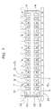
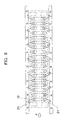
- Fig. 7 is a sectional plan view of the moving part of the high-thrust linear motor according to the embodiment of the present invention.
- Fig. 8 is a diagram showing the positional relationship between three-phase coils and field magnets in the high-thrust linear motor according to the embodiment of the present invention.
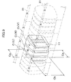
- Fig. 9 is an enlarged view of a part where the three-phase coils are wound.
- Fig. 10 is a cross-sectional view of a high-thrust linear motor according to another embodiment of the present invention.
- a high-thrust linear motor according to an embodiment of the present invention will be described below with reference to Figs. 4 to 9.
- Fig. 4 shows the sectional structure of the high-thrust linear motor.
- the high-thrust linear motor has a moving part 10, a stationary part 20, a linear guide 30, and a linear encoder 40.
- the moving part 10 is movably connected to the stationary part 20 through the linear guide 30 so as to be linearly slidable.
- the linear encoder 40 has a sensor moving part 41 secured to a side portion of the moving part 10.
- a linear scale 42 is secured to a side portion of the stationary part 20 to extend along it.
- the linear encoder 40 is adapted to detect a travel position of the moving part 10.
- the moving part 10 includes a core (magnetic member) 11 wound with coils C1, C2 and C3.
- a side core cover 12 and a top core cover 13 cover the core 11 and the coils C1, C2 and C3 approximately entirely, exclusive of effective conductor portions Cb thereof (see Fig. 9).
- Cover mounting plates (connecting members) 14 secure the core 11 to both the side core cover 12 and the top core cover 13.
- the moving part 10 further includes a table 15 on which an object to be conveyed is placed.
- the core 11 is composed of a stack of blanked magnetic steel sheets.
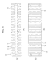
- Parts (A) and (B) of Fig. 6 are plan and side views showing the arrangement of the core 11.
- the core 11 has a plurality of teeth (salient poles) T and slots S formed alternately.
- the teeth T project from both sides of the core 11 in opposite directions intersecting the direction of the axis of the core 11.
- the slots S are each formed between a pair of adjacent teeth T.
- the coils C1, C2 and C3 are composed of three-phase coils, i.e. a U-phase coil C1, a W-phase coil C2, and a V-phase coil C3, which are wound in associated pairs of slots S on both sides of the core 11 one after another.
- the high-thrust linear motor according to this embodiment is a three-phase linear motor.
- the U-phase coil C1, the W-phase coil C2 and the V-phase coil C3 are wound in respective slots S in the order mentioned in such a manner that each pair of adjacent phases are different in electrical angle from each other.
- the coils C1, C2 and C3 wound on the core 11 constitute a three-phase armature in which three phases are displaced relative to one another by a 1/3 pitch with respect to the width Pm of one magnetic pole.
- each of the coils C1, C2 and C3 is divided into ineffective conductor portions Ca at the upper and lower ends thereof, which do not contribute to the generation of thrust, and an effective conductor portion Cb at a side portion thereof, which contributes to the generation of thrust.
- the side core cover 12 and the top core cover 13 constitute a pair of cover elements, which are formed from an aluminum-based material.
- the side core cover 12 is formed in a U-shape as seen in a sectional side view so as to cover the front, bottom and rear portions of the three-phase armature (the core 11 and the coils C1, C2 and C3).
- the side core cover 12 and the top core cover 13 are secured to each other through four cover mounting plates (connecting members) 14 inserted into respective slots S in the four corners of the core 11. That is, the four cover mounting plates 14 are secured at their lower ends to the side core cover 12 with screws and secured at their upper ends to the top core cover 13 with setscrews.
- cover mounting plates 14 are formed from an aluminum-based material having high thermal conductivity.
- the resin molded structure M includes the ineffective conductor portions Ca of the coils C1, C2 and C3. Filling of the epoxy resin material allows the side core cover 12, the top core cover 13 and the three-phase armature to be integrated in close contact with each other.
- the cooling pipe 16 is formed into a U-shape in external configuration and accommodated in the groove 13a on the upper surface of the top core cover 13. Both ends of the cooling pipe 16 are connected to couplings (half-unions) 18 through a coupling mounting plate 19 provided on one axial end of the moving part 10. The couplings 18 are connected to cooling pipings 17, respectively.
- the table 15 is connected to the upper surface of the top core cover 13 at the center of the lower surface thereof and further connected to sliding blocks 31 of the linear guide 30 at both sides of the lower surface thereof.
- An object to be conveyed is secured to the upper surface of the table 15.
- the sensor moving part 41 of the linear encoder 40 is secured to one side of the table 15 in such a manner that a sensor faces toward the stationary part 20.
- the yoke 22 has a groove portion 22a formed in the upper surface thereof.
- the groove portion 22a accommodates the three-phase armature of the moving part 10 and the field magnets 21. Accordingly, the width of the groove portion 22a is equal to the sum of the widths of the three-phase armature and the field magnets 21, together with the gaps therebetween.
- a pair of rails 32 constituting the linear guide 30 are secured to the upper surface of the yoke 22 at both sides of the groove portion 22a. Further, the linear scale 42 of the linear encoder 40 is secured to one side of the yoke 22 along the axis of the yoke 22. The linear scale 42 is fixed at a position facing the sensor of the sensor moving part 41.
- the field magnets 21 are secured to both side walls of the groove portion 22a of the yoke 22 along the axis of the yoke 22 at respective positions facing the effective conductor portions Cb of the coils C1, C2 and C3 of the three-phase armature in the moving part 10.
- the field magnets 21 are multipolar magnets magnetized in the sequence of a north pole, a south pole, a north pole ... so that each pair of mutually opposing poles of the field magnets 21 have the same polarity, thereby forming axial magnetic flux.
- the width of one magnetic pole of the field magnets 21 corresponds to the sum of the widths of three slots S in the core 11.
- the direction of the vector of the thrust F is not necessarily horizontal but may be obliquely upward or downward. Even when the direction of the vector of the thrust F is obliquely upward or downward, because the movement of the moving part 10 is restricted by the linear guide 30 so that the moving part 10 is slidable only in a horizontal axial direction, the moving part 10 moves horizontally and axially.
- the sensor moving part 41 secured to the moving part 10 detects the present position by detecting the linear scale 42 secured extendedly to the side wall of the stationary part 20.
- the side core cover 12 and the top core cover 13 cover the core 11 and the coils C1, C2 and C3 approximately entirely, exclusive of the effective conductor portions Cb thereof.
- the three-phase armature having the coils C1, C2 and C3 wound on approximately the whole area of the core 11 is covered with the side core cover 12 and the top core cover 13, whereby the three-phase armature is prevented from directly contacting the table 15 or other moving member and it can be surely secured through the side core cover 12 and the top core cover 13.
- the side core cover 12 and the top core cover 13 are provided as a pair of separate cover elements and the cover mounting plates 14 for integrally connecting the pair of cover elements are provided, it becomes easy to perform the operation of securing the core 11 and the coils C1, C2 and C3 to the side core cover 12 and the top core cover 13.
- cover mounting plates 14 an aluminum-based material having high thermal conductivity is used as a material of the cover mounting plates 14, and the cover mounting plates 14 are disposed in contact with or in close proximity to the core 11. Consequently, the cover mounting plates 14 act as a radiator, whereby heat generated from the coils C1, C2 and C3 can be dissipated to the outside without storing it in the core 11. Accordingly, it is possible to prevent reduction of thrust F as occurs when the core 11 is heated.
- two cover mounting plates 14a are inserted into two slots S in an intermediate portion of the core 101 in addition to four cover mounting plates 14a inserted into respective slots S in the four corners of the core 101.
- the mechanical strength of the side core cover 102 and the top core cover 103 can be increased because the cover mounting plates 14a are inserted into the slots S in the intermediate portion of the core 101 in addition to the cover mounting plates 14a inserted into the slots S in the four corners of the core 101. In addition, it is possible to dissipate heat from the intermediate portion of the core 101 through the cover mounting plates 14a provided therein.
- a core 11 is prepared in which a plurality of slots S are formed in series in the axial direction so as to extend from both sides of the core 11 in opposite directions intersecting the axial direction in corresponding relation to each other. Then, the core 11 is wound with coils C1, C2 and C3 one after another (see Fig. 7). In the coil winding process, each of the coils C1, C2 and C3 is wound in a pair of slots S on both sides of the core 11 while the core 11 is being rotated.
- coils are wound directly in slots of a core unlike the conventional process in which prewound coils are inserted into slots. Therefore, there will be no blank space where no coil is wound in the slots.
- slots are formed on both sides of a magnetic member, and coils are wound over both sides of the magnetic member through the respective slots. Therefore, the space efficiency (density) of the coils is increased, so that it is possible to obtain higher thrust than in the case of the conventional cored linear motor. Accordingly, it becomes possible to attain a compact cored linear motor.
- the coils have a plurality of phases and are wound in the respective pairs of slots in the magnetic member in such a manner that each pair of adjacent phases are different in electrical angle from each other. Therefore, it is possible to obtain a smooth operating condition equal to that obtained with a distributed winding type coil.
- the armature having the coils wound on approximately the entire area of the magnetic member is covered with a cover member, and the cover member is secured to a table or other moving member. Therefore, the armature is prevented from directly contacting the table or other moving member, and the armature can be surely secured to the table or the like through the cover member.
- the cover member is divided into a pair of cover elements, and the pair of cover elements are integrally connected together with connecting members. With this arrangement, the operation of securing the magnetic member and the coils to the cover member is further facilitated.
- the connecting members are formed from a material having high thermal conductivity and disposed in contact with or close proximity to the magnetic member. Therefore, the connecting members act as a radiator, whereby heat generated from the coils can be dissipated to the outside without storing it in the magnetic member. Accordingly, it is possible to prevent reduction of thrust as occurs when the magnetic member is heated.
- the magnetic member, the coils and the cover member are integrated in close contact with each other. Therefore, none of the magnetic member, the coils and the cover member will be deformed when the assembly of these members moves linearly or stops. Accordingly, the assembly of the magnetic member, the coils and the cover member is suitable for use as a moving part.
- a high-thrust linear motor has coils wound with a minimal blank space in slots of a magnetic member (core) to generate high thrust and permit smooth movement of a moving member.
- the high-thrust linear motor includes a magnetic member having a plurality of slots formed in series in an axial direction thereof. The slots extend from both sides of the magnetic member in opposite directions intersecting the axial direction in corresponding relation to each other. Coils having a plurality of phases are wound in respective pairs of slots on both sides of the magnetic member. Field magnets extend in the axial direction at both sides of the magnetic member so as to face an effective conductor portion of each coil. Each field magnet has a plurality of pairs of magnetic poles magnetized in the axial direction. According to a method of producing the high-thrust linear motor, coils are wound in respective pairs of slots on both sides of the magnetic member while the magnetic member is being rotated.
Landscapes
- Engineering & Computer Science (AREA)
- Physics & Mathematics (AREA)
- Chemical & Material Sciences (AREA)
- Combustion & Propulsion (AREA)
- Electromagnetism (AREA)
- Power Engineering (AREA)
- Linear Motors (AREA)
Applications Claiming Priority (2)
| Application Number | Priority Date | Filing Date | Title |
|---|---|---|---|
| JP2000024721A JP4527826B2 (ja) | 2000-01-28 | 2000-01-28 | 高推力リニアモータ及びその製造方法 |
| JP2000024721 | 2000-01-28 |
Publications (3)
| Publication Number | Publication Date |
|---|---|
| EP1120890A2 true EP1120890A2 (de) | 2001-08-01 |
| EP1120890A3 EP1120890A3 (de) | 2003-02-05 |
| EP1120890B1 EP1120890B1 (de) | 2010-06-02 |
Family
ID=18550662
Family Applications (1)
| Application Number | Title | Priority Date | Filing Date |
|---|---|---|---|
| EP01101717A Expired - Lifetime EP1120890B1 (de) | 2000-01-28 | 2001-01-25 | Linearmotor mit hohem Schub und sein Herstellungsverfahren |
Country Status (5)
| Country | Link |
|---|---|
| US (1) | US6777832B2 (de) |
| EP (1) | EP1120890B1 (de) |
| JP (1) | JP4527826B2 (de) |
| KR (1) | KR100709054B1 (de) |
| DE (1) | DE60142268D1 (de) |
Cited By (1)
| Publication number | Priority date | Publication date | Assignee | Title |
|---|---|---|---|---|
| EP3826152A1 (de) | 2019-11-19 | 2021-05-26 | Etel S.A. | Flüssigkeitsgekühlte kernanordnung für linearmotoren und linearmotor mit einer solchen kernanordnung |
Families Citing this family (16)
| Publication number | Priority date | Publication date | Assignee | Title |
|---|---|---|---|---|
| US7368837B2 (en) * | 2002-07-01 | 2008-05-06 | Thk Co., Ltd. | Drive guide device |
| JP4120787B2 (ja) * | 2002-10-08 | 2008-07-16 | 株式会社安川電機 | 直列配置リニアモータ |
| US7408276B2 (en) * | 2003-05-06 | 2008-08-05 | Canon Kabushiki Kaisha | Plane motor device with surrounding member surrounding coil unit and with cooling channel provided within surrounding member |
| US7026731B2 (en) * | 2003-06-20 | 2006-04-11 | Parker Hannifin Corp. | Linear motor glide assembly |
| JP2005237079A (ja) * | 2004-02-18 | 2005-09-02 | Toshiba Mach Co Ltd | リニア同期モータ |
| WO2005089327A2 (en) * | 2004-03-14 | 2005-09-29 | Revolution Electric Motor Company, Inc. | Commercial low cost, high efficiency motor-generator |
| JP2008517571A (ja) * | 2004-10-17 | 2008-05-22 | ドルマ ゲゼルシャフト ミット ベシュレンクテル ハフツング ウント コンパニー コマンディートゲゼルシャフト | 磁石列を伴う搬送システムおよび/または駆動システムを有するスライドドア |
| DE102006010198B4 (de) * | 2006-03-06 | 2008-02-07 | Siemens Ag | Direktantriebseinbaumotor mit spezieller Sensorbefestigung |
| EP2352221B1 (de) * | 2008-10-23 | 2018-05-23 | Sodick Co., Ltd. | Lineare motorspulenanordnung mit kühlelement |
| JP2016163407A (ja) * | 2015-02-27 | 2016-09-05 | 日立オートモティブシステムズ株式会社 | 電磁サスペンション用リニアモータ |
| MX2017015932A (es) * | 2015-06-11 | 2018-04-18 | Yuzen Sustainable Energy Co Ltd | Dispositivo electromagnetico. |
| US11296587B2 (en) * | 2016-11-30 | 2022-04-05 | Massachusetts Institute Of Technology | High force and low noise linear fine-tooth motor |
| KR101933689B1 (ko) * | 2017-04-26 | 2019-04-05 | 한국리니어기술 주식회사 | 리니어 모터용 가동자 및 가동자 제작 방법 |
| JP2019187218A (ja) * | 2018-04-17 | 2019-10-24 | Kyb株式会社 | 筒型リニアモータ |
| JP2019187212A (ja) * | 2018-04-17 | 2019-10-24 | Kyb株式会社 | 筒型リニアモータ |
| DE102018209724B4 (de) * | 2018-06-15 | 2025-12-24 | Krones Ag | Mover für ein Langstator-System |
Family Cites Families (23)
| Publication number | Priority date | Publication date | Assignee | Title |
|---|---|---|---|---|
| CH503415A (fr) * | 1968-12-20 | 1971-02-15 | Merlin Gerin | Moteur à induction linéaire |
| US3787716A (en) * | 1972-02-16 | 1974-01-22 | Aerospace Corp | Linear pulsed d.c. motor and controls therefor |
| GB1449469A (en) * | 1973-06-01 | 1976-09-15 | Lamb C St J | Linear electric motor systems |
| DE3006354C2 (de) * | 1979-02-26 | 1984-05-03 | Rostovskij-na-Donu institut inženerov železnodorožnogo transporta, Rostov-na-Donu | Zylindrischer linearer Asynchronmotor |
| JPS5986474A (ja) * | 1982-11-10 | 1984-05-18 | Takahashi Yoshiteru | 直流リニアモ−タ |
| KR900005760B1 (ko) | 1986-02-19 | 1990-08-09 | 가부시기가이샤 히다찌 세이사꾸쇼 | 가동코일형 리니어 모터 |
| JP2781912B2 (ja) | 1988-09-08 | 1998-07-30 | エヌティエヌ株式会社 | リニアモータ |
| JP2888142B2 (ja) * | 1993-11-08 | 1999-05-10 | 三菱電機株式会社 | 回転電動機並びにその製造方法 |
| JP2590276B2 (ja) * | 1989-12-25 | 1997-03-12 | 株式会社日立製作所 | 鉄輪式リニアモータ |
| JPH03265447A (ja) * | 1990-03-14 | 1991-11-26 | Shinko Electric Co Ltd | リニアモータのコア・コイル組立体とその成型方法 |
| JPH0583925A (ja) * | 1991-09-18 | 1993-04-02 | Toshiba Corp | 同期式リニアモータ |
| US5373120A (en) * | 1993-03-10 | 1994-12-13 | Otis Elevator Company | Linear door motor system for elevators |
| US5519266A (en) | 1993-06-01 | 1996-05-21 | Anorad Corporation | High efficiency linear motor |
| DE29505575U1 (de) * | 1994-05-04 | 1995-06-14 | Halm, Richard, 73666 Baltmannsweiler | Naßläufer-Spaltrohrmotor für Pumpen |
| US5808381A (en) | 1994-08-09 | 1998-09-15 | Hitachi Metals, Ltd. | Linear motor |
| JPH0870566A (ja) * | 1994-08-26 | 1996-03-12 | Toyota Auto Body Co Ltd | リニアモータの連結部構造 |
| KR0159675B1 (ko) | 1995-01-11 | 1999-01-15 | 오카노 사다오 | 공작 기계용 리니어 모터장치 |
| JP3309658B2 (ja) * | 1995-08-25 | 2002-07-29 | トヨタ自動車株式会社 | 内燃機関のバルブタイミング制御装置のための異常検出装置 |
| US5783877A (en) * | 1996-04-12 | 1998-07-21 | Anorad Corporation | Linear motor with improved cooling |
| JP3849128B2 (ja) * | 1997-03-14 | 2006-11-22 | 株式会社安川電機 | リニアモータ |
| JPH10313566A (ja) * | 1997-05-12 | 1998-11-24 | Jii M C:Kk | リニアモータ |
| JP3944799B2 (ja) * | 1997-12-12 | 2007-07-18 | 株式会社安川電機 | リニアモータ |
| US6239516B1 (en) | 1998-04-06 | 2001-05-29 | Kollmorgan Corporation | High performance ironless linear motor with supported windings |
-
2000
- 2000-01-28 JP JP2000024721A patent/JP4527826B2/ja not_active Expired - Fee Related
-
2001
- 2001-01-23 US US09/766,584 patent/US6777832B2/en not_active Expired - Fee Related
- 2001-01-25 EP EP01101717A patent/EP1120890B1/de not_active Expired - Lifetime
- 2001-01-25 DE DE60142268T patent/DE60142268D1/de not_active Expired - Lifetime
- 2001-01-26 KR KR1020010003777A patent/KR100709054B1/ko not_active Expired - Fee Related
Cited By (2)
| Publication number | Priority date | Publication date | Assignee | Title |
|---|---|---|---|---|
| EP3826152A1 (de) | 2019-11-19 | 2021-05-26 | Etel S.A. | Flüssigkeitsgekühlte kernanordnung für linearmotoren und linearmotor mit einer solchen kernanordnung |
| US11588378B2 (en) | 2019-11-19 | 2023-02-21 | Etel S.A. | Liquid-cooled core assembly for linear motors and linear motor comprising such core assembly |
Also Published As
| Publication number | Publication date |
|---|---|
| KR20010078092A (ko) | 2001-08-20 |
| KR100709054B1 (ko) | 2007-04-18 |
| US6777832B2 (en) | 2004-08-17 |
| DE60142268D1 (de) | 2010-07-15 |
| EP1120890A3 (de) | 2003-02-05 |
| JP2001218444A (ja) | 2001-08-10 |
| US20010010433A1 (en) | 2001-08-02 |
| JP4527826B2 (ja) | 2010-08-18 |
| EP1120890B1 (de) | 2010-06-02 |
Similar Documents
| Publication | Publication Date | Title |
|---|---|---|
| US6777832B2 (en) | High-thrust linear motor and method of producing the same | |
| US20240380256A1 (en) | Segmented stator for a permanent magnet electric machine having a fractional-slot concentrated winding | |
| JP3870413B2 (ja) | コアレスリニアモータ | |
| Cros et al. | New structures of polyphase claw-pole machines | |
| US6960858B2 (en) | Motor using permanent magnet | |
| US20080024014A1 (en) | Permanent magnet excited transverse flux linear motor with normal force compensation structure | |
| US20250175065A1 (en) | Switched reluctance machines without permanent magnets | |
| US9059626B2 (en) | Electric machine with linear mover | |
| JP3344645B2 (ja) | 永久磁石を用いたモータ | |
| JPH11262236A (ja) | リニアモータ | |
| WO2014141887A1 (ja) | リニアモータ | |
| US7242117B2 (en) | Linear motor | |
| WO2005057755A1 (en) | Polyphase claw-pole machines with a segmented magnetic circuit | |
| JP2009509491A (ja) | 永久磁石励磁同期電動機の一次側磁極部材に対する歯モジュール | |
| JP4110335B2 (ja) | リニアモータ | |
| JP2001197718A (ja) | コアレスリニアモータ | |
| US11955864B2 (en) | Linear motor | |
| JPH10323012A (ja) | リニアモータ | |
| JP3824060B2 (ja) | リニアモータ | |
| US20220069681A1 (en) | Method for winding a heavy gauge toroidal coil of an electric machine | |
| JP2006014391A (ja) | リニアモータ電機子、リニアモータおよび平面モータ | |
| JPH1118329A (ja) | 永久磁石形モータ | |
| JP6056570B2 (ja) | リニアモータ | |
| JP2025086239A (ja) | リニアモータ | |
| JPH04128085U (ja) | 移動テーブル |
Legal Events
| Date | Code | Title | Description |
|---|---|---|---|
| PUAI | Public reference made under article 153(3) epc to a published international application that has entered the european phase |
Free format text: ORIGINAL CODE: 0009012 |
|
| AK | Designated contracting states |
Kind code of ref document: A2 Designated state(s): AT BE CH CY DE DK ES FI FR GB GR IE IT LI LU MC NL PT SE TR |
|
| AX | Request for extension of the european patent |
Free format text: AL;LT;LV;MK;RO;SI |
|
| PUAL | Search report despatched |
Free format text: ORIGINAL CODE: 0009013 |
|
| AK | Designated contracting states |
Designated state(s): AT BE CH CY DE DK ES FI FR GB GR IE IT LI LU MC NL PT SE TR |
|
| AX | Request for extension of the european patent |
Extension state: AL LT LV MK RO SI |
|
| RIC1 | Information provided on ipc code assigned before grant |
Ipc: 7H 02K 41/03 A Ipc: 7H 02K 41/025 B |
|
| 17P | Request for examination filed |
Effective date: 20030403 |
|
| AKX | Designation fees paid |
Designated state(s): DE GB |
|
| 17Q | First examination report despatched |
Effective date: 20070416 |
|
| GRAP | Despatch of communication of intention to grant a patent |
Free format text: ORIGINAL CODE: EPIDOSNIGR1 |
|
| GRAS | Grant fee paid |
Free format text: ORIGINAL CODE: EPIDOSNIGR3 |
|
| RAP1 | Party data changed (applicant data changed or rights of an application transferred) |
Owner name: THK CO., LTD. |
|
| GRAA | (expected) grant |
Free format text: ORIGINAL CODE: 0009210 |
|
| AK | Designated contracting states |
Kind code of ref document: B1 Designated state(s): DE GB |
|
| REG | Reference to a national code |
Ref country code: GB Ref legal event code: FG4D |
|
| REF | Corresponds to: |
Ref document number: 60142268 Country of ref document: DE Date of ref document: 20100715 Kind code of ref document: P |
|
| PLBE | No opposition filed within time limit |
Free format text: ORIGINAL CODE: 0009261 |
|
| STAA | Information on the status of an ep patent application or granted ep patent |
Free format text: STATUS: NO OPPOSITION FILED WITHIN TIME LIMIT |
|
| 26N | No opposition filed |
Effective date: 20110303 |
|
| REG | Reference to a national code |
Ref country code: DE Ref legal event code: R097 Ref document number: 60142268 Country of ref document: DE Effective date: 20110302 |
|
| PGFP | Annual fee paid to national office [announced via postgrant information from national office to epo] |
Ref country code: DE Payment date: 20150120 Year of fee payment: 15 |
|
| PGFP | Annual fee paid to national office [announced via postgrant information from national office to epo] |
Ref country code: GB Payment date: 20150121 Year of fee payment: 15 |
|
| REG | Reference to a national code |
Ref country code: DE Ref legal event code: R119 Ref document number: 60142268 Country of ref document: DE |
|
| GBPC | Gb: european patent ceased through non-payment of renewal fee |
Effective date: 20160125 |
|
| PG25 | Lapsed in a contracting state [announced via postgrant information from national office to epo] |
Ref country code: GB Free format text: LAPSE BECAUSE OF NON-PAYMENT OF DUE FEES Effective date: 20160125 Ref country code: DE Free format text: LAPSE BECAUSE OF NON-PAYMENT OF DUE FEES Effective date: 20160802 |