EP1122368B1 - Engin de construction - Google Patents
Engin de construction Download PDFInfo
- Publication number
- EP1122368B1 EP1122368B1 EP00919133A EP00919133A EP1122368B1 EP 1122368 B1 EP1122368 B1 EP 1122368B1 EP 00919133 A EP00919133 A EP 00919133A EP 00919133 A EP00919133 A EP 00919133A EP 1122368 B1 EP1122368 B1 EP 1122368B1
- Authority
- EP
- European Patent Office
- Prior art keywords
- console
- operator
- notched groove
- lever
- seat
- Prior art date
- Legal status (The legal status is an assumption and is not a legal conclusion. Google has not performed a legal analysis and makes no representation as to the accuracy of the status listed.)
- Expired - Lifetime
Links
- 238000010276 construction Methods 0.000 title claims description 16
- 230000007246 mechanism Effects 0.000 claims description 34
- 230000000903 blocking effect Effects 0.000 claims description 15
- 230000009471 action Effects 0.000 description 17
- 230000000717 retained effect Effects 0.000 description 7
- 230000004048 modification Effects 0.000 description 2
- 238000012986 modification Methods 0.000 description 2
- 229920003002 synthetic resin Polymers 0.000 description 2
- 239000000057 synthetic resin Substances 0.000 description 2
- 230000004913 activation Effects 0.000 description 1
- 238000004873 anchoring Methods 0.000 description 1
- 230000009194 climbing Effects 0.000 description 1
- 239000000463 material Substances 0.000 description 1
- 239000002184 metal Substances 0.000 description 1
- 239000007769 metal material Substances 0.000 description 1
- 230000001681 protective effect Effects 0.000 description 1
- 230000002269 spontaneous effect Effects 0.000 description 1
Images




Classifications
-
- G—PHYSICS
- G05—CONTROLLING; REGULATING
- G05G—CONTROL DEVICES OR SYSTEMS INSOFAR AS CHARACTERISED BY MECHANICAL FEATURES ONLY
- G05G1/00—Controlling members, e.g. knobs or handles; Assemblies or arrangements thereof; Indicating position of controlling members
- G05G1/58—Rests or guides for relevant parts of the operator's body
- G05G1/62—Arm rests
-
- E—FIXED CONSTRUCTIONS
- E02—HYDRAULIC ENGINEERING; FOUNDATIONS; SOIL SHIFTING
- E02F—DREDGING; SOIL-SHIFTING
- E02F9/00—Component parts of dredgers or soil-shifting machines, not restricted to one of the kinds covered by groups E02F3/00 - E02F7/00
- E02F9/08—Superstructures; Supports for superstructures
- E02F9/10—Supports for movable superstructures mounted on travelling or walking gears or on other superstructures
-
- E—FIXED CONSTRUCTIONS
- E02—HYDRAULIC ENGINEERING; FOUNDATIONS; SOIL SHIFTING
- E02F—DREDGING; SOIL-SHIFTING
- E02F9/00—Component parts of dredgers or soil-shifting machines, not restricted to one of the kinds covered by groups E02F3/00 - E02F7/00
- E02F9/16—Cabins, platforms, or the like, for drivers
-
- E—FIXED CONSTRUCTIONS
- E02—HYDRAULIC ENGINEERING; FOUNDATIONS; SOIL SHIFTING
- E02F—DREDGING; SOIL-SHIFTING
- E02F9/00—Component parts of dredgers or soil-shifting machines, not restricted to one of the kinds covered by groups E02F3/00 - E02F7/00
- E02F9/20—Drives; Control devices
- E02F9/2004—Control mechanisms, e.g. control levers
Definitions
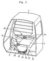
- the entrance gating lever 29 when in the blocking position (A) as shown in Fig. 2 , the entrance gating lever 29 is projected into the passage 9 to block the latter. On the other hand, when in the open position (B) or in the hydraulic locking position (C), the entrance gating lever 29 clears the passage 9.
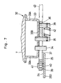
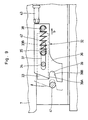
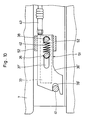
- the slide plate 36 is provided with the tapered surface 40 along its upper end on the upper side of the notched groove 39, so that, at the time of locking the console 24 in the operating position, the lock pin 41 can be guided smoothly toward and into the notched groove 39 by the tapered surface 40.
- the console 24 can be locked in the operating position by a smooth locking action.
Landscapes
- Engineering & Computer Science (AREA)
- Mining & Mineral Resources (AREA)
- Civil Engineering (AREA)
- General Engineering & Computer Science (AREA)
- Structural Engineering (AREA)
- Physics & Mathematics (AREA)
- General Physics & Mathematics (AREA)
- Automation & Control Theory (AREA)
- Component Parts Of Construction Machinery (AREA)
- Operation Control Of Excavators (AREA)
- Vehicle Step Arrangements And Article Storage (AREA)
Claims (6)
- Engin de chantier, comprenant en principe une carrosserie de véhicule munie d'un siège de conducteur (7) et d'une ouverture d'entrée (8) permettant d'accéder audit siège de conducteur et un dispositif formant console de commande (21) destinée à être manoeuvrée par un opérateur assis sur ledit siège de conducteur, ledit dispositif formant console de commande comprenant une console (24) disposée, avec la possibilité de pivoter dans le plan vertical, sur ladite carrosserie de véhicule dans une position contiguë à un côté du siège de conducteur et munie d'un levier de manoeuvre (27) destiné à être manipulé par ledit opérateur, un élément de commande de déplacement (28) poussant ladite console d'une position de disponibilité pour utilisation à une position renversée de repos, un levier de sélection d'entrée (29), monté pivotant sur un côté de ladite console et pouvant, par un mouvement de pivotement, être amené dans une position de blocage et une position d'ouverture et d'en être dégagé et un mécanisme de verrouillage permettant de verrouiller, avec une possibilité de dégagement ultérieur, ladite console sur le côté de ladite carrosserie de véhicule, ledit mécanisme de verrouillage étant agencé de manière à pouvoir être amené dans une position de déverrouillage au moyen dudit levier de sélection d'entrée, libérant ladite console pour qu'elle puisse être amenée dans une position de déverrouillage par rapport à une position de verrouillage maintenant ladite console dans ladite position de disponibilité pour utilisation, dans lequel ledit mécanisme de verrouillage dudit dispositif formant console de commande comprend :des saillies de support (34) disposées sur le côté dudit siège de conducteur et faisant saillie en direction de ladite console ;un élément (36), supporté par lesdites saillies de support, permettant des déplacements en alternance vers l'arrière et vers l'avant et muni d'une gorge formant encoche (39) au niveau de la portion d'extrémité antérieure de celui-ci ;une saillie de verrouillage (41) prévue sur le côté de ladite console et destinée à être amenée en prise d'engagement avec ladite gorge formant encoche lorsque ledit élément est amené par un déplacement vers l'avant dans ladite position de verrouillage et dégagé de son emprise d'engagement dans ladite gorge formant encoche lorsque ledit élément est amené par un déplacement vers l'arrière dans ladite position de déverrouillage ;un ressort de poussée (42) prévu entre ladite carrosserie de véhicule et ledit élément et agencé pour pousser ledit élément (36) dans sa direction de mise en prise d'engagement avec ladite rainure formant encoche ; etun organe de liaison (43) reliant ledit levier de sélection d'entrée et ledit élément et destiné à déplacer ledit élément vers l'arrière en contrant pour ce faire la force antagoniste opposée par ledit ressort de poussée en fonction d'une manoeuvre correspondante exercée sur ledit levier de sélection d'entrée,caractérisé en ce queledit élément étant en l'occurrence un élément coulissant (36) qui se déplace par glissement.
- Engin de chantier tel que défini dans la revendication 1, dans lequel ladite gorge formant encoche (39) a sensiblement une forme trapézoïdale allant en s'évasant vers l'extrémité ouverte donnant sur l'extérieur de celle-ci.
- Engin de chantier tel que défini dans la revendication 1 ou la revendication 2, dans lequel ladite gorge formant encoche (39) est définie dans ledit élément coulissant (36) par une portion formant paroi supérieure (39A) ayant une disposition sensiblement horizontale et par une portion formant paroi inférieure en pente (39B), inclinée vers le bas dans la direction antérieure.
- Engin de chantier tel que défini dans les revendications 1, 2 ou 3, dans lequel ledit élément coulissant (36) comprend une surface conique (40) se situant au niveau de la portion d'extrémité antérieure de la face supérieure de ladite gorge formant encoche, destinée à guider l'insertion de ladite saillie de verrouillage vers et dans ladite gorge formant encoche.
- Engin de chantier tel que défini dans les revendications 1, 2, 3 ou 4, dans lequel ledit élément coulissant (36) est muni d'une rainure (37) s'étendant dans un plan sensiblement horizontal dans la direction longitudinale de celui-ci et dans une position décalée dans le plan vertical de ladite gorge formant encoche (39), sur une distance prédéterminée, et lesdites saillies de support (34) s'engagent, avec la possibilité de coulisser, dans ladite rainure, pour permettre la réalisation de déplacements par un mouvement coulissant le long de celle-ci.
- Engin de chantier tel que défini dans les revendications 1, 2, 3, 4 ou 5, dans lequel une pluralité de saillies de support (34) est prévue sur un côté dudit siège de conducteur, à une certaine distance les uns des autres dans le plan horizontal.
Applications Claiming Priority (3)
| Application Number | Priority Date | Filing Date | Title |
|---|---|---|---|
| JP11413699A JP3609643B2 (ja) | 1999-04-21 | 1999-04-21 | 建設機械 |
| JP11413699 | 1999-04-21 | ||
| PCT/JP2000/002518 WO2000065160A1 (fr) | 1999-04-21 | 2000-04-18 | Engin de construction |
Publications (3)
| Publication Number | Publication Date |
|---|---|
| EP1122368A1 EP1122368A1 (fr) | 2001-08-08 |
| EP1122368A4 EP1122368A4 (fr) | 2002-10-30 |
| EP1122368B1 true EP1122368B1 (fr) | 2008-02-27 |
Family
ID=14630049
Family Applications (1)
| Application Number | Title | Priority Date | Filing Date |
|---|---|---|---|
| EP00919133A Expired - Lifetime EP1122368B1 (fr) | 1999-04-21 | 2000-04-18 | Engin de construction |
Country Status (6)
| Country | Link |
|---|---|
| US (1) | US6352133B1 (fr) |
| EP (1) | EP1122368B1 (fr) |
| JP (1) | JP3609643B2 (fr) |
| KR (1) | KR100398935B1 (fr) |
| DE (1) | DE60038157T2 (fr) |
| WO (1) | WO2000065160A1 (fr) |
Families Citing this family (27)
| Publication number | Priority date | Publication date | Assignee | Title |
|---|---|---|---|---|
| JP3798572B2 (ja) * | 1999-04-19 | 2006-07-19 | 日立建機株式会社 | 建設機械用キャブ |
| JP4488329B2 (ja) * | 2000-12-05 | 2010-06-23 | 株式会社小松製作所 | 建設機械車両の操縦系ロックレバー装置 |
| JP3785944B2 (ja) * | 2001-03-30 | 2006-06-14 | 日産自動車株式会社 | 車両用の操作部配置構造 |
| US6971194B2 (en) * | 2003-06-24 | 2005-12-06 | Cnh America Llc | Modular backhoe-excavator control station |
| US7036250B2 (en) * | 2003-09-12 | 2006-05-02 | Deere & Company | Latchless controller tower |
| JP4373820B2 (ja) * | 2004-03-11 | 2009-11-25 | 日立建機株式会社 | 作業機械の前後進操作装置 |
| CN1842626A (zh) * | 2004-07-20 | 2006-10-04 | 株式会社小松制作所 | 操作机构箱装置 |
| WO2006033399A1 (fr) * | 2004-09-24 | 2006-03-30 | Komatsu Ltd. | Module de commande de giration, procede de commande de giration et engin de chantier |
| KR100652873B1 (ko) * | 2005-02-18 | 2006-12-01 | 볼보 컨스트럭션 이키프먼트 홀딩 스웨덴 에이비 | 굴삭기 운전실내 안전레버 시스템 |
| US7726745B2 (en) * | 2005-10-27 | 2010-06-01 | Crown Equipment Corporation | Adjustable armrest mechanism for a materials handling vehicle |
| US7797918B2 (en) * | 2005-12-27 | 2010-09-21 | The Toro Company | Mower with flip up armrest carrying operational controls and display |
| DE102006022113A1 (de) * | 2006-05-11 | 2007-11-15 | Jungheinrich Ag | Flurförderzeug |
| JP4486662B2 (ja) * | 2007-06-15 | 2010-06-23 | キャタピラージャパン株式会社 | 建設機械のコンソール高さ調整装置 |
| JP4609900B2 (ja) * | 2007-09-14 | 2011-01-12 | キャタピラー エス エー アール エル | 作業機械の作業レバー取付体跳ね上げ装置 |
| JP5122896B2 (ja) * | 2007-09-25 | 2013-01-16 | 日立建機株式会社 | 建設機械の排気ガス浄化システム |
| US8820463B2 (en) * | 2011-09-27 | 2014-09-02 | Shane Phillips | Safety control systems and methods for heavy equipment |
| EP2574699B1 (fr) | 2011-09-30 | 2014-04-30 | Caterpillar, Inc. | Blocage de sécurité d'une sortie de cabine |
| USD689529S1 (en) * | 2012-05-10 | 2013-09-10 | Hitachi Construction Machinery Co., Ltd. | Console for construction machine |
| CN103541400B (zh) * | 2013-10-18 | 2016-04-27 | 徐州徐工特种工程机械有限公司 | 一种挖掘装载机支腿油缸保护机构 |
| JP5850022B2 (ja) * | 2013-10-30 | 2016-02-03 | コベルコ建機株式会社 | 作業機械 |
| USD730948S1 (en) * | 2014-01-24 | 2015-06-02 | Kobelco Construction Machinery Co., Ltd. | Console box for construction machine |
| CN107077162B (zh) * | 2016-10-21 | 2018-10-19 | 株式会社小松制作所 | 作业车辆 |
| EP3190236B1 (fr) * | 2016-10-21 | 2019-09-18 | Komatsu, Ltd. | Engin de travail avec console de controle |
| WO2018079879A1 (fr) * | 2016-10-27 | 2018-05-03 | 볼보 컨스트럭션 이큅먼트 에이비 | Appareil pour retenir un corps pivotant supérieur d'une machine de construction |
| JP7266879B2 (ja) * | 2019-12-26 | 2023-05-01 | スターテング工業株式会社 | コンソールのチルト構造 |
| CN114875996B (zh) * | 2022-05-31 | 2025-08-08 | 柳州鸿嘉机械有限公司 | 一种装载机操纵箱的底座自锁结构 |
| WO2024143188A1 (fr) * | 2022-12-26 | 2024-07-04 | 株式会社クボタ | Dispositif de levier et engin de mise en œuvre équipé de ce dernier |
Family Cites Families (17)
| Publication number | Priority date | Publication date | Assignee | Title |
|---|---|---|---|---|
| US4388980A (en) * | 1981-01-26 | 1983-06-21 | Clark Equipment Company | Operator restraint for a loader |
| NL8200614A (nl) * | 1982-02-17 | 1983-09-16 | Rotterdamsche Droogdok Mij | Bedrijfsvoertuig. |
| JPS59183957U (ja) * | 1983-05-20 | 1984-12-07 | 株式会社小松製作所 | 建設機械の操縦装置 |
| JPS63179520A (ja) | 1987-01-21 | 1988-07-23 | Hitachi Ltd | 有磁場マイクロ波プラズマ処理装置 |
| JPS63179520U (fr) * | 1987-05-01 | 1988-11-21 | ||
| JPH0266861U (fr) * | 1988-11-08 | 1990-05-21 | ||
| JP2567720B2 (ja) | 1990-05-25 | 1996-12-25 | 日立建機株式会社 | 作業機械 |
| JP2603000B2 (ja) | 1991-01-24 | 1997-04-23 | 日立建機株式会社 | 車両系建設機械の安全装置 |
| JPH0685456A (ja) | 1992-08-31 | 1994-03-25 | Taiyo Yuden Co Ltd | グリーンシートへのスルーホール導体形成方法 |
| US5341895A (en) * | 1993-03-18 | 1994-08-30 | Ingersoll-Rand Company | Movable control console |
| JPH08284212A (ja) | 1995-04-13 | 1996-10-29 | Shin Caterpillar Mitsubishi Ltd | 走行作業機の走行レバー固定装置 |
| JP2989522B2 (ja) * | 1995-07-28 | 1999-12-13 | 新キャタピラー三菱株式会社 | 作業用走行車の操作部構造 |
| US5617929A (en) * | 1995-10-10 | 1997-04-08 | Paccar Inc | Movable shift console |
| KR980009677A (ko) * | 1996-07-31 | 1998-04-30 | 김무 | 중장비용 안전레버장치 |
| US5924515A (en) * | 1997-03-17 | 1999-07-20 | New Holland North America, Inc. | Operator seat sliding control console |
| JPH11202960A (ja) * | 1998-01-09 | 1999-07-30 | Komatsu Est Corp | 作業用車両の作業機レバー支持構造 |
| US6164285A (en) * | 1998-03-16 | 2000-12-26 | Case Corporation | Position-adjustable control console |
-
1999
- 1999-03-21 US US09/700,995 patent/US6352133B1/en not_active Expired - Fee Related
- 1999-04-21 JP JP11413699A patent/JP3609643B2/ja not_active Expired - Fee Related
-
2000
- 2000-04-18 DE DE60038157T patent/DE60038157T2/de not_active Expired - Lifetime
- 2000-04-18 WO PCT/JP2000/002518 patent/WO2000065160A1/fr not_active Ceased
- 2000-04-18 KR KR10-2000-7014511A patent/KR100398935B1/ko not_active Expired - Fee Related
- 2000-04-18 EP EP00919133A patent/EP1122368B1/fr not_active Expired - Lifetime
Also Published As
| Publication number | Publication date |
|---|---|
| KR20010071547A (ko) | 2001-07-28 |
| DE60038157D1 (de) | 2008-04-10 |
| JP3609643B2 (ja) | 2005-01-12 |
| EP1122368A1 (fr) | 2001-08-08 |
| DE60038157T2 (de) | 2009-02-19 |
| JP2000303502A (ja) | 2000-10-31 |
| WO2000065160A1 (fr) | 2000-11-02 |
| KR100398935B1 (ko) | 2003-09-19 |
| EP1122368A4 (fr) | 2002-10-30 |
| US6352133B1 (en) | 2002-03-05 |
Similar Documents
| Publication | Publication Date | Title |
|---|---|---|
| US6352133B1 (en) | Construction machinery | |
| EP0447119B1 (fr) | Engin de terrassement | |
| EP2105538B1 (fr) | Plateforme pour opérateur dans un véhicule de travail | |
| JP4609900B2 (ja) | 作業機械の作業レバー取付体跳ね上げ装置 | |
| US9534354B2 (en) | Construction machine | |
| JP4056937B2 (ja) | 作業機の操作装置 | |
| CA2279169C (fr) | Support stationnaire pour tractochargeur | |
| JPH0672444B2 (ja) | 超小型ショベルカーの座席装置 | |
| ES2348227T3 (es) | Dispositivo de bloqueo para una pluma. | |
| JP3666678B2 (ja) | コントロールボックスの開閉装置 | |
| JP3532790B2 (ja) | 建設機械及びそれに用いるコンソール装置 | |
| JP6648045B2 (ja) | 小型油圧ショベル | |
| JP4247211B2 (ja) | トラクタ・ローダ・バックホーにおける掘削装置のロック機構 | |
| JP2000096626A (ja) | 建設機械の操作パターン切換装置 | |
| JP3535397B2 (ja) | 建設機械の運転席装置 | |
| US6435053B1 (en) | Actuating arrangement with interlock to prevent unintended actuation when in a non-operating position | |
| US5446982A (en) | Motion controller handrest with lever lock | |
| JPH0634435Y2 (ja) | 小旋回型バックホーにおけるキャノピールーフ構造 | |
| JP2008025141A (ja) | 作業用機械における乗降遮断装置 | |
| JPS5828043Y2 (ja) | 作業車のア−ム下降阻止構造 | |
| JPH10204923A (ja) | 建設機械の操作レバー装置 | |
| JP4793925B2 (ja) | 作業機械における乗降遮断装置 | |
| KR100648958B1 (ko) | 휠타입 굴삭기의 램실린더 제어장치 | |
| JPH0443123A (ja) | 作業車の屋根構造 | |
| JPH05214740A (ja) | 作業車の操作具取付構造 |
Legal Events
| Date | Code | Title | Description |
|---|---|---|---|
| PUAI | Public reference made under article 153(3) epc to a published international application that has entered the european phase |
Free format text: ORIGINAL CODE: 0009012 |
|
| 17P | Request for examination filed |
Effective date: 20010423 |
|
| AK | Designated contracting states |
Kind code of ref document: A1 Designated state(s): AT BE CH CY DE DK ES FI FR GB GR IE IT LI LU MC NL PT SE |
|
| A4 | Supplementary search report drawn up and despatched |
Effective date: 20020917 |
|
| AK | Designated contracting states |
Kind code of ref document: A4 Designated state(s): DE GB IT NL |
|
| RBV | Designated contracting states (corrected) |
Designated state(s): DE GB IT NL |
|
| GRAP | Despatch of communication of intention to grant a patent |
Free format text: ORIGINAL CODE: EPIDOSNIGR1 |
|
| GRAS | Grant fee paid |
Free format text: ORIGINAL CODE: EPIDOSNIGR3 |
|
| GRAA | (expected) grant |
Free format text: ORIGINAL CODE: 0009210 |
|
| AK | Designated contracting states |
Kind code of ref document: B1 Designated state(s): DE GB IT NL |
|
| REG | Reference to a national code |
Ref country code: GB Ref legal event code: FG4D |
|
| REF | Corresponds to: |
Ref document number: 60038157 Country of ref document: DE Date of ref document: 20080410 Kind code of ref document: P |
|
| PLBE | No opposition filed within time limit |
Free format text: ORIGINAL CODE: 0009261 |
|
| STAA | Information on the status of an ep patent application or granted ep patent |
Free format text: STATUS: NO OPPOSITION FILED WITHIN TIME LIMIT |
|
| 26N | No opposition filed |
Effective date: 20081128 |
|
| PG25 | Lapsed in a contracting state [announced via postgrant information from national office to epo] |
Ref country code: IT Free format text: LAPSE BECAUSE OF FAILURE TO SUBMIT A TRANSLATION OF THE DESCRIPTION OR TO PAY THE FEE WITHIN THE PRESCRIBED TIME-LIMIT Effective date: 20080227 |
|
| PGFP | Annual fee paid to national office [announced via postgrant information from national office to epo] |
Ref country code: GB Payment date: 20140416 Year of fee payment: 15 |
|
| PGFP | Annual fee paid to national office [announced via postgrant information from national office to epo] |
Ref country code: NL Payment date: 20140308 Year of fee payment: 15 |
|
| GBPC | Gb: european patent ceased through non-payment of renewal fee |
Effective date: 20150418 |
|
| REG | Reference to a national code |
Ref country code: NL Ref legal event code: MM Effective date: 20150501 |
|
| PG25 | Lapsed in a contracting state [announced via postgrant information from national office to epo] |
Ref country code: GB Free format text: LAPSE BECAUSE OF NON-PAYMENT OF DUE FEES Effective date: 20150418 |
|
| PG25 | Lapsed in a contracting state [announced via postgrant information from national office to epo] |
Ref country code: NL Free format text: LAPSE BECAUSE OF NON-PAYMENT OF DUE FEES Effective date: 20150501 |
|
| PGFP | Annual fee paid to national office [announced via postgrant information from national office to epo] |
Ref country code: DE Payment date: 20160412 Year of fee payment: 17 |
|
| REG | Reference to a national code |
Ref country code: DE Ref legal event code: R119 Ref document number: 60038157 Country of ref document: DE |
|
| PG25 | Lapsed in a contracting state [announced via postgrant information from national office to epo] |
Ref country code: DE Free format text: LAPSE BECAUSE OF NON-PAYMENT OF DUE FEES Effective date: 20171103 |