EP1130219A1 - Turbine avec joints d'étanchéitée entre les panneaux des parois - Google Patents
Turbine avec joints d'étanchéitée entre les panneaux des parois Download PDFInfo
- Publication number
- EP1130219A1 EP1130219A1 EP00104346A EP00104346A EP1130219A1 EP 1130219 A1 EP1130219 A1 EP 1130219A1 EP 00104346 A EP00104346 A EP 00104346A EP 00104346 A EP00104346 A EP 00104346A EP 1130219 A1 EP1130219 A1 EP 1130219A1
- Authority
- EP
- European Patent Office
- Prior art keywords
- sealing element
- turbine system
- turbine
- plate elements
- adjacent
- Prior art date
- Legal status (The legal status is an assumption and is not a legal conclusion. Google has not performed a legal analysis and makes no representation as to the accuracy of the status listed.)
- Withdrawn
Links
- 238000007789 sealing Methods 0.000 claims abstract description 75
- 238000002485 combustion reaction Methods 0.000 claims abstract description 18
- 239000007789 gas Substances 0.000 description 31
- 230000008646 thermal stress Effects 0.000 description 6
- 238000001816 cooling Methods 0.000 description 5
- 239000002826 coolant Substances 0.000 description 4
- 238000005516 engineering process Methods 0.000 description 4
- 238000004519 manufacturing process Methods 0.000 description 4
- 238000003466 welding Methods 0.000 description 3
- 239000002737 fuel gas Substances 0.000 description 2
- 239000000463 material Substances 0.000 description 2
- 239000002184 metal Substances 0.000 description 2
- 238000005452 bending Methods 0.000 description 1
- 230000000694 effects Effects 0.000 description 1
- 230000003628 erosive effect Effects 0.000 description 1
- 230000001771 impaired effect Effects 0.000 description 1
- 238000000034 method Methods 0.000 description 1
- 238000010248 power generation Methods 0.000 description 1
- 230000002787 reinforcement Effects 0.000 description 1
Images

Classifications
-
- F—MECHANICAL ENGINEERING; LIGHTING; HEATING; WEAPONS; BLASTING
- F01—MACHINES OR ENGINES IN GENERAL; ENGINE PLANTS IN GENERAL; STEAM ENGINES
- F01D—NON-POSITIVE DISPLACEMENT MACHINES OR ENGINES, e.g. STEAM TURBINES
- F01D11/00—Preventing or minimising internal leakage of working-fluid, e.g. between stages
- F01D11/005—Sealing means between non relatively rotating elements
-
- F—MECHANICAL ENGINEERING; LIGHTING; HEATING; WEAPONS; BLASTING
- F23—COMBUSTION APPARATUS; COMBUSTION PROCESSES
- F23R—GENERATING COMBUSTION PRODUCTS OF HIGH PRESSURE OR HIGH VELOCITY, e.g. GAS-TURBINE COMBUSTION CHAMBERS
- F23R3/00—Continuous combustion chambers using liquid or gaseous fuel
- F23R3/002—Wall structures
-
- F—MECHANICAL ENGINEERING; LIGHTING; HEATING; WEAPONS; BLASTING
- F05—INDEXING SCHEMES RELATING TO ENGINES OR PUMPS IN VARIOUS SUBCLASSES OF CLASSES F01-F04
- F05D—INDEXING SCHEME FOR ASPECTS RELATING TO NON-POSITIVE-DISPLACEMENT MACHINES OR ENGINES, GAS-TURBINES OR JET-PROPULSION PLANTS
- F05D2260/00—Function
- F05D2260/20—Heat transfer, e.g. cooling
- F05D2260/205—Cooling fluid recirculation, i.e. after cooling one or more components is the cooling fluid recovered and used elsewhere for other purposes
-
- F—MECHANICAL ENGINEERING; LIGHTING; HEATING; WEAPONS; BLASTING
- F05—INDEXING SCHEMES RELATING TO ENGINES OR PUMPS IN VARIOUS SUBCLASSES OF CLASSES F01-F04
- F05D—INDEXING SCHEME FOR ASPECTS RELATING TO NON-POSITIVE-DISPLACEMENT MACHINES OR ENGINES, GAS-TURBINES OR JET-PROPULSION PLANTS
- F05D2260/00—Function
- F05D2260/20—Heat transfer, e.g. cooling
- F05D2260/232—Heat transfer, e.g. cooling characterized by the cooling medium
- F05D2260/2322—Heat transfer, e.g. cooling characterized by the cooling medium steam
-
- F—MECHANICAL ENGINEERING; LIGHTING; HEATING; WEAPONS; BLASTING
- F23—COMBUSTION APPARATUS; COMBUSTION PROCESSES
- F23M—CASINGS, LININGS, WALLS OR DOORS SPECIALLY ADAPTED FOR COMBUSTION CHAMBERS, e.g. FIREBRIDGES; DEVICES FOR DEFLECTING AIR, FLAMES OR COMBUSTION PRODUCTS IN COMBUSTION CHAMBERS; SAFETY ARRANGEMENTS SPECIALLY ADAPTED FOR COMBUSTION APPARATUS; DETAILS OF COMBUSTION CHAMBERS, NOT OTHERWISE PROVIDED FOR
- F23M2900/00—Special features of, or arrangements for combustion chambers
- F23M2900/05005—Sealing means between wall tiles or panels
-
- F—MECHANICAL ENGINEERING; LIGHTING; HEATING; WEAPONS; BLASTING
- F23—COMBUSTION APPARATUS; COMBUSTION PROCESSES
- F23R—GENERATING COMBUSTION PRODUCTS OF HIGH PRESSURE OR HIGH VELOCITY, e.g. GAS-TURBINE COMBUSTION CHAMBERS
- F23R2900/00—Special features of, or arrangements for continuous combustion chambers; Combustion processes therefor
- F23R2900/00012—Details of sealing devices
-
- F—MECHANICAL ENGINEERING; LIGHTING; HEATING; WEAPONS; BLASTING
- F23—COMBUSTION APPARATUS; COMBUSTION PROCESSES
- F23R—GENERATING COMBUSTION PRODUCTS OF HIGH PRESSURE OR HIGH VELOCITY, e.g. GAS-TURBINE COMBUSTION CHAMBERS
- F23R2900/00—Special features of, or arrangements for continuous combustion chambers; Combustion processes therefor
- F23R2900/03044—Impingement cooled combustion chamber walls or subassemblies
Definitions
- the invention relates to a turbine system, in particular one Gas turbine plant.
- a plant is called a gas turbine plant understood that a combustion chamber and one of the combustion chamber subordinate turbine designated as a gas turbine.
- a combustion chamber burns a fuel gas in a gas space, and the hot gas generated thereby is fed to the turbine and flows through them.
- the flow path of the hot gas through the Turbine is also referred to below as a gas space.
- the turbine has fixed vanes that differ from extend radially outside into the gas space, as well as on a Runners designated shaft mounted blades that shovel on extend radially outward from the rotor. Longitudinal Looking at the turbine, the guide vanes and the grab The blades shovel into one another tooth-like.
- the turbine has in usually several turbine stages, with one in each stage Guide vane ring is arranged, i.e. several of the vanes are arranged side by side in the circumferential direction of the turbine.
- the individual guide vane rings are axial Direction sequentially arranged.
- the gas space is usually clad with panel elements. Are at the combustion chamber this is tiling, and in the turbine are the plate elements formed by so-called base plates of the individual guide vanes.
- the gas area of the combustion chamber and the turbine should be as possible be tight. Therefore, there is little leakage loss between the individual plate elements. In particular should prevent leakage losses between two turbine stages become.
- As a result of the large temperature ranges in the gas space there is a problem that sealing stretches the individual Plate elements must take up and bridge without that the seal is significantly impaired. Reinforced this problem is caused by the fact that both the tiles as well the base plates of the guide vane are not at their edge areas are attached to adjacent plate elements so that the Plate edges are more or less free and a bend as a result are subject to thermal expansion.
- the tiles are usually attached in the middle and bend approximately spherically under thermal stress.
- a seal must therefore - also because of the axial direction conical design of the combustion chamber and the turbine - both allow axial as well as radial mobility.
- the invention has for its object to provide a seal enable that overcomes the disadvantages described.
- a turbine system in particular gas turbine plant with a gas space
- the outside through adjacent plate elements is limited, each with a sealing element adjacent to each other Plate elements is assigned and this at their the Back sides facing away from the gas space are connected in a clamp-like manner.
- the main advantage here is in the bracket-like To see the design of the sealing element.
- the sealing element thus spans the two plate elements. With thermal The sealing element follows the plate elements without stretching to release a gap. The sealing by the sealing element is therefore largely unaffected by thermal expansion.
- the sealing element makes it possible to ensure expansion preferably a mobility of the plate elements both in the axial as well as in the radial direction.
- the sealing element is therefore both in the axial and in the radial direction especially elastic. In the axial direction becomes an expansion in the longitudinal direction of the turbine system and in the radial direction an expansion perpendicular understood to the longitudinal axis.
- the sealing element preferably has two legs that each in a groove of adjacent plate elements to grab. This makes it easy to manufacture enables fastening of the sealing elements to be realized.
- the groove preferably extends from the rear of the respective Plate element in this essentially radial inside.
- the legs therefore protrude radially outwards from the grooves.
- This configuration of the groove enables a simple one Manufacturing and in particular high accuracy, for example by grinding or eroding.
- the advantage of the arrangement on the back you can see that the groove in the No special one with regard to the problem of thermal expansions Form. Groove and sealing element can therefore can be adapted very precisely to one another, so that very little Leakage gaps can be achieved.
- the sealing element In order to assemble the plate elements in the turbine system a simple procedure is the sealing element preferably constructed in several parts.
- the legs of the multi-part preferably overlap Sealing element over a common circumferential length. This The circumferential length is large enough to prevent leaks largely avoided.
- the sealing element is U-shaped trained in both manufacturing and assembly technology is easy to implement.
- the sealing element expediently has this corrugated Structure in several directions so that it stretches in can take different directions.
- the sealing element is double S-shaped.
- the sealing element is between adjacent tiles of a combustion chamber arranged. So that will achieved a secure seal between the tiles, itself if they are spherical due to the thermal load to bend.
- the sealing element is between the base plates of adjacent guide vanes a turbine arranged, in particular between the Base plates of guide blades of neighboring turbine stages.
- the individual base plates are therefore in the axial or longitudinal direction the turbine via clamp-like sealing elements connected.
- the further sealing element preferably has a receiving area into which the plate elements extend.
- the sealing element is in cross section seen H-shaped.
- the basic idea of this Design is the reverse of a conventional sealing principle can be seen in which a sealing plate in corresponding front grooves of the foot plates is introduced. This requires namely usually a reinforcement of the edge of the Foot plates in the groove area. This is for good cooling of the Foot plates problematic because of the different Even cooling is difficult to achieve with material thicknesses and thermal stresses can occur.
- this sealing principle is now not the sealing plate inserted in the footplates, but the footplates are introduced into the sealing element. This eliminates the Need to reinforce the edge area of the footplate. The coolability is thus simplified and the base plate is cooled homogeneously in all areas, so that none thermal stresses occur.
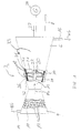
- a turbine system 1 comprises a turbine system 2, in particular one Gas turbine system of a turbo set for a power plant Power generation, a combustion chamber 4 and a turbine 6, the in the longitudinal or axial direction 8 of the turbine system 2 after the Brennkammmer 4 is arranged. Both the combustion chamber 4 and The turbine 6 is also cut open in a partial area shown. This is a look into the gas space 10 of the combustion chamber 4 and in the gas space 12 of the turbine 6.
- the combustion chamber 4 is connected to a gas supply 14 a fuel gas BG supplied, which is in the gas space 10 of the combustion chamber 4 is burned and forms a hot gas HG.
- the gas room 10 is formed with a plurality of plate elements Tiles 13 lined.
- the hot gas HG flows through the turbine 6 and leaves it as a cold gas KG via a Gas discharge 16.
- the hot gas HG is in the turbine 6 Guide vanes 18 and 20 blades. Doing so a shaft 22 driven on which the blades 20 are arranged are.
- the shaft 22 is connected to a generator 24.
- the blades 20 extend radially from the shaft 22 outward.
- the guide vanes 18 have a base plate 32 and an attached blade 21.
- the guide vanes 18 are each on the outside of the turbine via their base plates 32 6 attached to a so-called guide vane carrier 26 and extend radially into the gas space 12.
- the guide vanes 18 and the blades 20 tooth-like into each other.
- Several of the barrel scoops 20 as well the guide vanes 18 are combined to form a ring, each vane ring having a turbine stage represents.
- FIG 1 is the second turbine stage 28 and the third turbine stage 30 by way of example shown.
- the base plates 32 of the individual guide vanes 18 are also as the tiles 13 formed as plate elements that are against each other both in the axial direction 8 and in the circumferential direction 33 of the turbine 6 adjoin one another and the gas space 12 limit.
- the one marked with a circle in FIG. 1 The position is shown enlarged in FIGS. 2 to 4.
- the too these figures described seal between two in particular in the longitudinal direction 8 adjacent footplates 32 can also be used as a seal for the tiles 13 transferred to the combustion chamber 4.
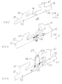
- the foot plates 32 according to FIGS. 2 to 4 have on their from Back side 39 facing away from gas space 12 each has a hooking element 40 on the foot plates 32 on the vane carrier 26 (see FIG. 1) are held.
- Each footplate 32 has typically two interlocking elements 40, which are different are designed and both an agility enable in the axial direction 8 as well as in the radial direction 36.
- FIG 3 shows a further conventional sealing arrangement a sealing plate 41, which in grooves 44 of the adjacent Foot plates 32 is inserted.
- the grooves 44 are there incorporated into the end faces 46 of the foot plates 32.
- she have an opening angle ⁇ of approximately 15 ° to a To allow mobility of the foot plates 32 in the radial direction 36.
- Also in this embodiment is between the Sealing plate 41 and the base plates 32 formed a leakage gap 38, the one with the stretch due to the thermal load varies.
- the foot plates 32 expand faster than the vane carrier 26 to which they are attached.
- the problems of the temperature dependence of the leakage gap 38 occurs in the novel design according to FIG 4 does not open. After that are in the area where the two Adjoin foot plates 32 with 39 grooves in the rear 44 incorporated, which essentially radially into the Extend footplates 32. It should be emphasized that the grooves 44 in accordance with FIG. 4 in contrast to those of FIG. 3 in parallel Have side walls 50. This enables a particularly simple one Making the grooves 44.
- a U-shaped sealing element 42A In the grooves 44 is a U-shaped sealing element 42A with its introduced both legs 52 and in particular attached. The attachment takes place, for example, by a clamping action or by welding.
- the sealing element 42A is special executed as a sheet metal element. His legs 52 extend essentially radially outwards, so that the arch 54 connecting the two legs 52 is spaced from the back 39. This stretched version enables elastic behavior of the sealing element 42A, i.e. it follows the thermal expansion of the foot plates 32. The thermal mobility of the foot plates 32 is thus ensured by the flexible or stretchable sealing element 42A. The mobility is therefore independent of the special design of the grooves 44, so that this very can be adapted to the legs 52. Between the leg 52 and the grooves 44 is therefore none or only a very small leakage gap 38 is formed, which is independent of the thermal stress on the foot plates 32.
- FIG. 5 is a sealing element 42B formed from two separate legs 52, which each have an arc 54 and over overlap a circumferential length L.
- the multi-part training of the sealing element 42B simplifies the assembly because, for example the individual legs 52 before assembly of the Guide vanes 18 simply into the corresponding grooves 44 of the respective foot plates 32 are attached and then these can be attached to the guide vane carrier 26.
- the common The circumferential length L is chosen to be as large as possible the leakage gap 38 formed between them for all temperature and to keep operating conditions low.
- a sealing element 42C In an alternative multi-part design of a sealing element 42C according to FIG. 6 is only one leg 52A provided with an arch 54, whereas the second leg 52B is a straight piece of sheet metal.
- the multi-part training Sealing elements 42B, 42C it is advantageous if the individual Leg 52 are pressed against each other in the assembled state and, for example, have a certain spring tension.
- FIG. 7 is a sealing element 42D with a corrugated Structure 58 provided that the simply designed arch 54th replaced according to Figures 4 to 6.
- This corrugated structure 58 preferably extends in several directions, in particular in both directions parallel to the foot plates 32.
- the legs 52 can also be corrugated.
- the Sealing element 42D is thus in the manner of a bellows trained and enables even large thermal expansions in several directions without the leakage gap 38 is enlarged.
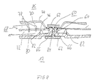
- the sealing elements 42A to 42D connect from assembly technology Base preferably the base plates 32 of guide vanes 18 adjacent turbine stages 28,30. To also in the circumferential direction 33 a good and easy to install seal to achieve is adjacent to each other in the circumferential direction 33 Guide vanes 18 of another guide vane ring Sealing element 60 is provided.
- the further sealing element 60 is preferably shown in FIG Cross section seen H-shaped and has two Longitudinal leg 62 on each other via a cross leg 64 are connected. Between the two longitudinal legs 62 are two receiving areas 65 separated from the cross leg 64 formed, into which the foot plates 32 extend. The margins 66 of the foot plates 32 are approximately perpendicular to the gas space 12 turned outwards and nestle immediately to the cross leg 64.
- This configuration with the receiving areas 65 for the foot plates 32 advantageously allows one over the entire base plate 32 homogeneous material thickness, so that a uniform cooling of the base plate 32 is guaranteed and Thermal stress in the foot plate 32 does not occur.
- Cooling system 68 To cool the foot plates 32, a closed one is used in particular Cooling system 68 provided with steam as the coolant, the is shown in detail in FIG 8.
- This closed Cooling system 68 has an inflow channel 70 and one Reverse flow channel 72.
- the inflow channel 70 is between one outer baffle 74 and a baffle plate 76, which arranged between the guide plate 74 and the foot plate 32 is.
- the baffle 76 has flow openings 78 which are designed in the manner of nozzles, so that this via the inflow channel 70 supplied coolant along the illustrated Arrows in the return flow passage 72. Because of the nozzle-like Operation of the flow openings 78 will High speed coolant against the rear 80 of the foot plate 32, so that an effective heat transfer realized between the coolant and the base plate 21 is.
- the baffle 76 is via support elements 82, for example in the form of welding spots or welding bars, against the footplate 32 supported and kept spaced.
- the baffle 70 is directly attached to the side edge 66 of the foot plate 32, in particular welded, and the baffle 68 is on Baffle plate 70 attached.
- a flow path 84 in the form of a leakage gap formed so that the outer space facing away from the gas space 12 86, for example, air via flow path 84 in can flow the gas space 12 and thus the sealing area, thus the sealing element 60 and the side edges 66 cools.
Landscapes
- Engineering & Computer Science (AREA)
- Mechanical Engineering (AREA)
- General Engineering & Computer Science (AREA)
- Chemical & Material Sciences (AREA)
- Combustion & Propulsion (AREA)
- Turbine Rotor Nozzle Sealing (AREA)
Priority Applications (7)
| Application Number | Priority Date | Filing Date | Title |
|---|---|---|---|
| EP00104346A EP1130219A1 (fr) | 2000-03-02 | 2000-03-02 | Turbine avec joints d'étanchéitée entre les panneaux des parois |
| JP2001563750A JP4637435B2 (ja) | 2000-03-02 | 2001-02-23 | タービン設備 |
| US10/220,200 US6702549B2 (en) | 2000-03-02 | 2001-02-23 | Turbine installation |
| CNB01805904XA CN1272525C (zh) | 2000-03-02 | 2001-02-23 | 透平机装置 |
| PCT/EP2001/002094 WO2001065073A1 (fr) | 2000-03-02 | 2001-02-23 | Installation de turbine |
| EP01927701A EP1268981B1 (fr) | 2000-03-02 | 2001-02-23 | Installation de turbine |
| DE50106206T DE50106206D1 (de) | 2000-03-02 | 2001-02-23 | Turbinenanlage |
Applications Claiming Priority (1)
| Application Number | Priority Date | Filing Date | Title |
|---|---|---|---|
| EP00104346A EP1130219A1 (fr) | 2000-03-02 | 2000-03-02 | Turbine avec joints d'étanchéitée entre les panneaux des parois |
Publications (1)
| Publication Number | Publication Date |
|---|---|
| EP1130219A1 true EP1130219A1 (fr) | 2001-09-05 |
Family
ID=8168008
Family Applications (2)
| Application Number | Title | Priority Date | Filing Date |
|---|---|---|---|
| EP00104346A Withdrawn EP1130219A1 (fr) | 2000-03-02 | 2000-03-02 | Turbine avec joints d'étanchéitée entre les panneaux des parois |
| EP01927701A Expired - Lifetime EP1268981B1 (fr) | 2000-03-02 | 2001-02-23 | Installation de turbine |
Family Applications After (1)
| Application Number | Title | Priority Date | Filing Date |
|---|---|---|---|
| EP01927701A Expired - Lifetime EP1268981B1 (fr) | 2000-03-02 | 2001-02-23 | Installation de turbine |
Country Status (5)
| Country | Link |
|---|---|
| EP (2) | EP1130219A1 (fr) |
| JP (1) | JP4637435B2 (fr) |
| CN (1) | CN1272525C (fr) |
| DE (1) | DE50106206D1 (fr) |
| WO (1) | WO2001065073A1 (fr) |
Cited By (8)
| Publication number | Priority date | Publication date | Assignee | Title |
|---|---|---|---|---|
| EP1302723A1 (fr) | 2001-10-15 | 2003-04-16 | Siemens Aktiengesellschaft | Revêtement pour parois intérieures de chambre de combustion |
| EP1310735A1 (fr) | 2001-11-12 | 2003-05-14 | Rolls-Royce Deutschland Ltd & Co KG | Ensemble écran thermique comportant des éléments d'étanchéité |
| EP1580403A1 (fr) * | 2004-03-26 | 2005-09-28 | Snecma | Joint d'étanchéité entre les carters intérieur et extérieur d'une section de turboréacteur |
| RU2364793C2 (ru) * | 2004-01-27 | 2009-08-20 | Сименс Акциенгезелльшафт | Теплозащитный экран, элемент теплозащитного экрана, удерживающий элемент, камера сгорания с теплозащитным экраном, жаровая труба и газовая турбина |
| US7870738B2 (en) | 2006-09-29 | 2011-01-18 | Siemens Energy, Inc. | Gas turbine: seal between adjacent can annular combustors |
| EP2463583A1 (fr) * | 2010-12-06 | 2012-06-13 | Alstom Technology Ltd | Turbine à gaz et procédé de reconditionnement d'une telle turbine à gaz |
| EP2530362A1 (fr) * | 2011-06-03 | 2012-12-05 | General Electric Company | Joint de torsion |
| EP3051068A1 (fr) * | 2015-02-02 | 2016-08-03 | MTU Aero Engines GmbH | Bague d'aube directrice pour une turbomachine et procédé de fabrication additive |
Families Citing this family (5)
| Publication number | Priority date | Publication date | Assignee | Title |
|---|---|---|---|---|
| DE102010031124A1 (de) * | 2010-07-08 | 2012-01-12 | Man Diesel & Turbo Se | Strömungsmaschine |
| DE102010063594A1 (de) | 2010-12-20 | 2012-06-21 | Mtu Aero Engines Gmbh | Dichtanordnung und Turbomaschine mit einer derartigen Dichtanordnung |
| CN104379877B (zh) * | 2012-06-18 | 2016-06-15 | 通用电器技术有限公司 | 在静态涡轮部件之间的密封件 |
| DE102017207667A1 (de) | 2017-05-08 | 2018-11-08 | Siemens Aktiengesellschaft | Verfahren zum Instandhalten einer Strömungsmaschine |
| CN109653816B (zh) * | 2019-01-23 | 2024-05-10 | 江苏核电有限公司 | 一种用于汽轮机自带围带叶片的撑顶工具及其撑顶方法 |
Citations (5)
| Publication number | Priority date | Publication date | Assignee | Title |
|---|---|---|---|---|
| US2991045A (en) * | 1958-07-10 | 1961-07-04 | Westinghouse Electric Corp | Sealing arrangement for a divided tubular casing |
| US2999631A (en) * | 1958-09-05 | 1961-09-12 | Gen Electric | Dual airfoil |
| EP0616112A1 (fr) * | 1993-03-11 | 1994-09-21 | ROLLS-ROYCE plc | Système de joint d'étanchéité pour turbine à gaz |
| US5735671A (en) * | 1996-11-29 | 1998-04-07 | General Electric Company | Shielded turbine rotor |
| WO1998053228A1 (fr) * | 1997-05-21 | 1998-11-26 | Allison Advanced Development Company | Dispositif de scellement d'aubes entre etages |
Family Cites Families (5)
| Publication number | Priority date | Publication date | Assignee | Title |
|---|---|---|---|---|
| US4199151A (en) * | 1978-08-14 | 1980-04-22 | General Electric Company | Method and apparatus for retaining seals |
| CA2031085A1 (fr) * | 1990-01-16 | 1991-07-17 | Michael P. Hagle | Etancheite entre anneaux de distributeur de turbine |
| US5158305A (en) * | 1992-01-31 | 1992-10-27 | Eg&G Pressure Science, Inc. | Pressure-energized two-element seal |
| JPH1150805A (ja) * | 1997-08-06 | 1999-02-23 | Mitsubishi Heavy Ind Ltd | ガスタービン静翼シュラウドのシール構造 |
| GB2335470B (en) * | 1998-03-18 | 2002-02-13 | Rolls Royce Plc | A seal |
-
2000
- 2000-03-02 EP EP00104346A patent/EP1130219A1/fr not_active Withdrawn
-
2001
- 2001-02-23 JP JP2001563750A patent/JP4637435B2/ja not_active Expired - Fee Related
- 2001-02-23 DE DE50106206T patent/DE50106206D1/de not_active Expired - Lifetime
- 2001-02-23 WO PCT/EP2001/002094 patent/WO2001065073A1/fr not_active Ceased
- 2001-02-23 CN CNB01805904XA patent/CN1272525C/zh not_active Expired - Fee Related
- 2001-02-23 EP EP01927701A patent/EP1268981B1/fr not_active Expired - Lifetime
Patent Citations (5)
| Publication number | Priority date | Publication date | Assignee | Title |
|---|---|---|---|---|
| US2991045A (en) * | 1958-07-10 | 1961-07-04 | Westinghouse Electric Corp | Sealing arrangement for a divided tubular casing |
| US2999631A (en) * | 1958-09-05 | 1961-09-12 | Gen Electric | Dual airfoil |
| EP0616112A1 (fr) * | 1993-03-11 | 1994-09-21 | ROLLS-ROYCE plc | Système de joint d'étanchéité pour turbine à gaz |
| US5735671A (en) * | 1996-11-29 | 1998-04-07 | General Electric Company | Shielded turbine rotor |
| WO1998053228A1 (fr) * | 1997-05-21 | 1998-11-26 | Allison Advanced Development Company | Dispositif de scellement d'aubes entre etages |
Cited By (16)
| Publication number | Priority date | Publication date | Assignee | Title |
|---|---|---|---|---|
| EP1302723A1 (fr) | 2001-10-15 | 2003-04-16 | Siemens Aktiengesellschaft | Revêtement pour parois intérieures de chambre de combustion |
| US6840047B2 (en) | 2001-10-15 | 2005-01-11 | Siemens Aktiengesellschaft | Lining for inner walls of combustion chambers |
| EP1310735A1 (fr) | 2001-11-12 | 2003-05-14 | Rolls-Royce Deutschland Ltd & Co KG | Ensemble écran thermique comportant des éléments d'étanchéité |
| US6901757B2 (en) | 2001-11-12 | 2005-06-07 | Rolls-Royce Deutschland Ltd & Co Kg | Heat shield arrangement with sealing element |
| RU2364793C2 (ru) * | 2004-01-27 | 2009-08-20 | Сименс Акциенгезелльшафт | Теплозащитный экран, элемент теплозащитного экрана, удерживающий элемент, камера сгорания с теплозащитным экраном, жаровая труба и газовая турбина |
| EP1580403A1 (fr) * | 2004-03-26 | 2005-09-28 | Snecma | Joint d'étanchéité entre les carters intérieur et extérieur d'une section de turboréacteur |
| FR2868119A1 (fr) * | 2004-03-26 | 2005-09-30 | Snecma Moteurs Sa | Joint d'etancheite entre les carters interieurs et exterieurs d'une section de turboreacteur |
| US7870738B2 (en) | 2006-09-29 | 2011-01-18 | Siemens Energy, Inc. | Gas turbine: seal between adjacent can annular combustors |
| EP2463583A1 (fr) * | 2010-12-06 | 2012-06-13 | Alstom Technology Ltd | Turbine à gaz et procédé de reconditionnement d'une telle turbine à gaz |
| CH704185A1 (de) * | 2010-12-06 | 2012-06-15 | Alstom Technology Ltd | Gasturbine sowie verfahren zum rekonditionieren einer solchen gasturbine. |
| AU2011253595B2 (en) * | 2010-12-06 | 2015-07-16 | General Electric Technology Gmbh | Gas turbine and method for reconditioning such a gas turbine |
| EP2530362A1 (fr) * | 2011-06-03 | 2012-12-05 | General Electric Company | Joint de torsion |
| US8544852B2 (en) | 2011-06-03 | 2013-10-01 | General Electric Company | Torsion seal |
| EP3051068A1 (fr) * | 2015-02-02 | 2016-08-03 | MTU Aero Engines GmbH | Bague d'aube directrice pour une turbomachine et procédé de fabrication additive |
| DE102015201782A1 (de) * | 2015-02-02 | 2016-08-18 | MTU Aero Engines AG | Leitschaufelring für eine Strömungsmaschine |
| US10280775B2 (en) | 2015-02-02 | 2019-05-07 | MTU Aero Engines AG | Guide vane ring for a turbomachine |
Also Published As
| Publication number | Publication date |
|---|---|
| JP4637435B2 (ja) | 2011-02-23 |
| JP2003525381A (ja) | 2003-08-26 |
| CN1408048A (zh) | 2003-04-02 |
| EP1268981B1 (fr) | 2005-05-11 |
| EP1268981A1 (fr) | 2003-01-02 |
| CN1272525C (zh) | 2006-08-30 |
| DE50106206D1 (de) | 2005-06-16 |
| WO2001065073A1 (fr) | 2001-09-07 |
Similar Documents
| Publication | Publication Date | Title |
|---|---|---|
| EP1389690B1 (fr) | Vis intérieurement refroidissable | |
| EP1276972B1 (fr) | Turbine | |
| DE69723495T2 (de) | Kühlung von Gasturbinenbrennkammerwand | |
| DE69926332T2 (de) | Bürstendichtung für eine Turbomaschine | |
| DE2622234C2 (de) | Vorrichtung zur Zuführung von Kühlluft in das Flammrohr von Gasturbinen-Brennkammern | |
| DE69309794T2 (de) | Düsenhalterung für Turbinen | |
| DE3510230C2 (de) | Brennkammer für ein Gasturbinentriebwerk | |
| EP1268981B1 (fr) | Installation de turbine | |
| EP1443275A1 (fr) | Chambre de combustion | |
| DE3446389A1 (de) | Statoraufbau fuer ein gasturbinen-triebwerk | |
| EP1656497B1 (fr) | Diffuseur situe entre le compresseur et la chambre de combustion d'une turbine a gaz | |
| EP2184445A1 (fr) | Support d'aubes statorique axialement segmenté d'une turbine à gaz | |
| EP0806548A1 (fr) | Turbine d'un turbocompresseur à gaz d'échappement | |
| DE1601679A1 (de) | Statoranordnung fuer Turbinen | |
| DE602004001546T2 (de) | Dichtungssystem für den Nebenstrom am Einlass der Nachbrennerdüse einer Turbomaschine | |
| WO2001009553A1 (fr) | Dispositif de refroidissement par choc | |
| EP1165942B1 (fr) | Turbomachine avec un systeme d'elements de paroi pouvant etre refroidi et procede de refroidissement d'un systeme d'elements de paroi | |
| EP0838595A2 (fr) | Support pour aube pour un compresseur | |
| EP2347101B1 (fr) | Turbine à gaz et moteur à turbine à gaz associé | |
| CH643050A5 (de) | Gasturbinentriebwerk mit ringbrennkammer. | |
| EP1724526A1 (fr) | Coquille de turbine à gaz, turbine à gaz et procédé de démarrage et d'arrêt d'une turbine à gaz | |
| EP1398569A1 (fr) | Turbine à gaz | |
| EP1422479B1 (fr) | Chambre pour la combustion d' un mélange combustible fluide | |
| DE69917170T2 (de) | Kühlungssystem für heisse turbinenteile | |
| EP1529181B1 (fr) | Chambre de combustion de turbine a gaz |
Legal Events
| Date | Code | Title | Description |
|---|---|---|---|
| PUAI | Public reference made under article 153(3) epc to a published international application that has entered the european phase |
Free format text: ORIGINAL CODE: 0009012 |
|
| AK | Designated contracting states |
Kind code of ref document: A1 Designated state(s): AT BE CH CY DE DK ES FI FR GB GR IE IT LI LU MC NL PT SE |
|
| AX | Request for extension of the european patent |
Free format text: AL;LT;LV;MK;RO;SI |
|
| AKX | Designation fees paid | ||
| REG | Reference to a national code |
Ref country code: DE Ref legal event code: 8566 |
|
| STAA | Information on the status of an ep patent application or granted ep patent |
Free format text: STATUS: THE APPLICATION IS DEEMED TO BE WITHDRAWN |
|
| 18D | Application deemed to be withdrawn |
Effective date: 20020306 |