EP1134491A2 - Vorrichtung zur Beleuchtung einer Blickspitze und System zur Beleuchtung eines chirurgischen Eingriffs mit einer solchen - Google Patents
Vorrichtung zur Beleuchtung einer Blickspitze und System zur Beleuchtung eines chirurgischen Eingriffs mit einer solchen Download PDFInfo
- Publication number
- EP1134491A2 EP1134491A2 EP01105730A EP01105730A EP1134491A2 EP 1134491 A2 EP1134491 A2 EP 1134491A2 EP 01105730 A EP01105730 A EP 01105730A EP 01105730 A EP01105730 A EP 01105730A EP 1134491 A2 EP1134491 A2 EP 1134491A2
- Authority
- EP
- European Patent Office
- Prior art keywords
- illuminating device
- gazing
- gazing point
- led
- leds
- Prior art date
- Legal status (The legal status is an assumption and is not a legal conclusion. Google has not performed a legal analysis and makes no representation as to the accuracy of the status listed.)
- Withdrawn
Links
Images





Classifications
-
- G—PHYSICS
- G06—COMPUTING OR CALCULATING; COUNTING
- G06F—ELECTRIC DIGITAL DATA PROCESSING
- G06F3/00—Input arrangements for transferring data to be processed into a form capable of being handled by the computer; Output arrangements for transferring data from processing unit to output unit, e.g. interface arrangements
- G06F3/01—Input arrangements or combined input and output arrangements for interaction between user and computer
- G06F3/011—Arrangements for interaction with the human body, e.g. for user immersion in virtual reality
- G06F3/013—Eye tracking input arrangements
-
- A—HUMAN NECESSITIES
- A61—MEDICAL OR VETERINARY SCIENCE; HYGIENE
- A61B—DIAGNOSIS; SURGERY; IDENTIFICATION
- A61B90/00—Instruments, implements or accessories specially adapted for surgery or diagnosis and not covered by any of the groups A61B1/00 - A61B50/00, e.g. for luxation treatment or for protecting wound edges
- A61B90/30—Devices for illuminating a surgical field, the devices having an interrelation with other surgical devices or with a surgical procedure
-
- G—PHYSICS
- G02—OPTICS
- G02C—SPECTACLES; SUNGLASSES OR GOGGLES INSOFAR AS THEY HAVE THE SAME FEATURES AS SPECTACLES; CONTACT LENSES
- G02C11/00—Non-optical adjuncts; Attachment thereof
- G02C11/04—Illuminating means
-
- F—MECHANICAL ENGINEERING; LIGHTING; HEATING; WEAPONS; BLASTING
- F21—LIGHTING
- F21W—INDEXING SCHEME ASSOCIATED WITH SUBCLASSES F21K, F21L, F21S and F21V, RELATING TO USES OR APPLICATIONS OF LIGHTING DEVICES OR SYSTEMS
- F21W2131/00—Use or application of lighting devices or systems not provided for in codes F21W2102/00-F21W2121/00
- F21W2131/20—Lighting for medical use
Definitions
- the present invention relates to a multi-purpose gazing point illuminating device which can change the lighting direction corresponding to the gazing direction of the user. It further relates to a surgical operation illuminating system that uses the same device.
- a so-called astral lighting system For a light in an operation room of a hospital, a so-called astral lighting system has been used to illuminate the part of operation with high illuminance without casting shadows there.
- An astral lighting system is constructed so that many lamps are embedded in a large dish-like base which is suspended from the ceiling of the operation room. Therefore, for its placement, a large room is needed and the ceiling of the operation room must be adequately high. Furthermore, because of its very heavy weight, not only the ceiling but also the whole operation room is required to be structurally strong. As a result, the construction cost of an operation room is high due to this lighting system.
- an operator needs to look at the part of operation from the side, not from the high as shown in Fig. 11.
- the operator needs to look at the anal from side.
- another side lighting system is necessary to directly illuminate the part. Since it is normally impossible to use a side lamp as large as the astral lighting system on the ceiling, the operator is sometimes required to take a clumsy or unnatural position for avoiding his own shadow cast on the part of operation.
- the lighting direction can be changed freely corresponding to the part to be cared.
- an easy and portable device that can illuminate a necessary point is required because conventional lighting systems are hard to carry around.
- the present invention is achieved in this respect placing its primary object to provide a gazing point illuminating device that can light in a desired direction easily and illuminate an object point without making a shadow. Another object is to provide a portable gazing point illuminating device for illuminating a desired point without requiring a clumsy posture of the user. Preferably it can be used in a surgical operation.
- a gazing point illuminating device is provided with: a light source; a direction changing mechanism for changing the lighting direction of the light source; a gazing direction detector for detecting the direction of the user's gazing line; and a controller for changing the lighting direction corresponding to the detected gazing direction.
- the user's gazing direction is detected and the lighting direction of the light source is changed corresponding to the detected gazing direction, so that the gazing point of the user is always illuminated automatically.
- the device is used in a surgical operation, for example, the operating doctor need not take a clumsy posture as was conventionally required, and the part of operation can be illuminated assuredly and safely.
- the device is used in the case of a home medical care or a nursing care, the part to be cared can be illuminated according to the doctor's or care-taker's gazing direction.
- an EL (Electro-Luminescence) panel may be used as the light source.
- An EL panel is a lighting device using a thin-film electroluminescent element.
- the inorganic EL type includes those using manganese added zinc sulfide (ZnS:Mn), terbium added zinc sulfide (ZnS:Tb), cerium added strontium sulfide (SrS:Ce), cerium added strontium thiogallate (SrGa2S4:Ce), etc.
- the organic EL type includes those using tetraphenyl-diamine derivatives (TPD), polyvinyl-carbazole (PVK), aluminum-quinolinol complex (Alq3), distyryl-biphenyl derivatives (DPVBi), etc.
- TPD tetraphenyl-diamine derivatives
- PVK polyvinyl-carbazole
- Alq3 aluminum-quinolinol complex
- DPVBi distyryl-biphenyl derivatives
- the EL panel used in the present invention may be shaped flat or concave against the lighting direction. When it is shaped concave so that the light from the whole EL panel is converged to an object point or object area, the illuminating efficiency is very high.
- the light source may be an LED (Light Emitting Diode) panel in which an LED or a plurality of LEDs are arranged on a base board.
- the number of LEDs on an LED panel depends on the strength of the LED used and the brightness needed by the illuminating device using the LED panel.
- a plurality of LEDs may be arranged on the base board one-dimensionally (straight or curve) or two-dimensionally.
- the base board can be flat or concave against the lighting direction, as described above for the EL panel.
- An LED has a high energy-converting efficiency. Compared to conventional incandescent lamps, its energy consumption is greatly reduced and the heat generation is thus minimized. When it is used in a surgical operation where the part of operation needs to be cooled, the operation can be performed without a powerful cooling system.
- An LED has other great advantages of longlife and lightweight.
- the illuminating device of the present invention using an LED panel also has the same advantages over conventional illuminating devices.
- the cost can be greatly reduced compared to the conventional astral lighting system which claims a large construction cost and requires a costly cooling system.
- the illuminating device of the present invention realizes an energy-saving, lightweight and longlife white light source which can replace conventional incandescent lamps or fluorescent lamps.
- White LEDs can be fabricated either by the combination of LEDs emitting at blue, green and red spectral range, or by the combination of blue LEDs and phosphors.
- Latter type of white LEDs for example, consist of InGaN-based LED and YAG-phosphor, whose spectra are composed of two emission bands, where the blue band peaking at 460 nm is the emission from InGaN quantum-well-active layers, and the broad yellow band at 560 nm is the one from YAG phosphor.
- the LED panel may be composed of a set or a plurality of sets consisting of a red (R) LED, a green (G) LED and a (B) LED.
- R red
- G green
- B blue
- the strengths of the three primary colors can be preset so that the color of the skin or blood looks natural.
- the intensity distribution in the red spectral region is very important to render inherent color of raw flesh such as skin, blood, fat tissue and internal organs. This can be achieved by adding red LEDs in the array of white LEDs or white LED chips.
- the LED panel may include an ultraviolet LED or LEDs.
- the ultraviolet light from the illuminating device of the present invention excites a fluorescent signing attached to an object beforehand.
- morbid parts, such as a tumor, attached by a fluorescent signing can be made exclusively visible.
- the ultraviolet LEDs may be used alone, with white LEDs or with the RGB LEDs in the LED panel.
- all kinds of LEDs may be lit simultaneously, or they may be switched depending on the situation or purpose of illumination.
- LEDs placed on the base board may be packaged type LEDs or chip type LEDs.
- An LED itself is as small as 0.5 mm or less.
- an LED is normally packaged in a cannonball-shaped transparent plastic case of about several millimeters with two lead wires drawn outside.
- the gazing point illuminating device of the present invention such individually packaged LEDs may be used, or alternatively, the chip type LEDs may be used.
- the chip type LEDs are used, the size and area of the LED panel can be far smaller than that using individually packaged LEDs for the same light emitting strength. This leads to a smaller light source and thus to a far smaller, lightweight gazing point illuminating device.
- the illuminating device of the present invention may include a dimming controller for changing the lighting strength of the light source, whereby the gazing object can be illuminated at an arbitrary illuminance.
- the light source includes LEDs of various colors (including the case where ultraviolet LEDs are included), it is preferable to control the lighting strengths of respective colors.
- a color controller including R-, G- and B-dimming controllers for the respective colors can change the color of the light arbitrarily. If the gazing point illuminating device is used in a surgical operation or in a home medical care, the illuminance and the color can be changed easily as the operator desires. In some important cases, during a surgical operation, a slight color change of the light from the gazing point illuminating device will render clear difference in color of two parts showing similar colors otherwise.
- the dimming control of the LEDs can be effected by a knob or the like. Alternatively, it may be effected by a voice recognition device which responds to the user's voice of verbal order, such as "on", “off", “light up” or “light down”.
- the gazing direction detector determines the gazing direction of an eye by detecting a reflection of light projected to an eyeball.
- the gazing direction is detected from the distribution of the light reflected by the surface of the eyeball.
- a beam of light is projected to an eyeball and the direction of the reflected beam is detected.
- the direction changing mechanism may change the lighting direction by tilting the light source vertically and/or horizontally. In this way, the lighting direction can be changed according to the gazing direction.
- the direction changing mechanism may include a lens for refracting the light from the light source.
- the lens is tilted vertically and/or horizontally so that, as described above, the lighting direction can be changed corresponding to the gazing direction.
- the gazing point illuminating device of the present invention may be attached to the user's body such as chest or abdomen, or it may be settled at a certain place of a room. It is also possible that the gazing point illuminating device of the present invention is attached to goggles or eyeglasses. When the goggles or eyeglasses according to the present invention are worn by a user, the user's shadow will never be cast on the gazing point. This is especially suited for use in a surgical operation. Besides the normal function of goggles to prevent blotting of blood or other stains on the wearer's eyes, they assure clear illumination of the part of operation without demanding a clumsy posture of the operator during an operation.
- the part is illuminated by the goggles of the people from diverse directions so that the illuminance is stronger and shadowing is more effectively avoided. Further advantage is that the goggles or eyeglasses are portable, which enables them to be easily used in home medical care or other field medical or nursing care. Conventional lighting devices could not have done it.
- two sets of light sources are provided corresponding to the left and right eyes.
- the gazing direction detectors detect the gazing directions of the left and right eyes independently, and the controller control the direction changing mechanism to change respective light sources' lighting directions corresponding to the detected left and right gazing directions. Since normally the left and right eyes' gazing lines cross at the gazing object, a greater illuminance and shadow-free illumination is obtained at the gazing object.
- more than two light sources may be employed, of course.
- the two light sources may be placed at the left and right ends of the front face of goggles. This style neatly utilizes the free space of the far ends of the goggles.
- the gazing direction detector may determine the gazing direction by detecting the point on a piece of eyeshield of the goggles or on a piece of glass of the eyeglasses where the gazing line penetrates.
- the whole area of a piece of eyeshield or a piece of glass is divided into a plurality of sub-areas.
- a plurality of lighting directions are predetermined for the light source.
- the controller brings the lighting direction of the light source to the direction corresponding to the detected sub-area. This is a rather simple way of detecting the gazing direction.
- the surgical operation illuminating system of the present invention uses the gazing point illuminating device as described above, which detects the operator's gazing direction and change the lighting direction of the light source accordingly.
- the operator need not take a clumsy posture during an operation.
- the light source is always directed to the gazing object while the operator takes a variety of postures necessary for the operation. The accuracy of the operation will be improved greatly.
- gazing point illuminating devices are constructed so that they detect the user's gazing direction and change the lighting direction accordingly.
- the lighting direction normally accords with the gazing direction of the wearer, unless the wearer intentionally averts the eyes.
- Japanese Unexamined Utility Model Publication Nos. S56-156022 and S57-22720 disclose eyeglasses with a lamp at the center of the upper frame.
- Japanese Unexamined Utility Model Publication No. H6-7702 discloses eyeglasses for medical use to which an ordinary lamp is placed at the upper frame (paragraph [0021] of the publication).
- Japanese Utility Model Registration No. 3049423 discloses goggles for otolaryngologists which have lamps at the lower-left corner of the frame besides at the upper center.
- Japanese Unexamined Patent Publication No. 2000-39595 discloses eyeglasses with ordinary lamps on both temples.
- an LED panel or an EL panel which are very compact and lightweight, are used for the light source.
- the LEDs are arrayed one-dimensionally (straight or curve) or two-dimensionally.
- an EL panel an appropriate shape is cut out to fit the goggles or eyeglasses.
- the LEDs or EL panel are so lightweight that the goggles or eyeglasses according to the present invention weigh almost the same as ordinary ones without such a light source.
- a practical gazing point illuminating device is realized by the present invention without causing fatigue to the wearer after wearing a long time.
- an LED panel is preferable because of its strong light, high efficiency and long life.
- the LED panel or panels, or EL panel or panels may be placed at the upper frame or lower frame of the goggles or eyeglasses. It is more preferable to attach them at the left and right ends of the front face of the goggles because they make a larger cross angle of the lighting directions which provides a better shadow-free illumination.
- An LED has a high energy converting efficiency.
- heat generation is greatly reduced and the energy consumption is saved.
- the cost for a surgical operation illuminating system can be greatly reduced since the conventional large astral lighting system and a large cooling system are no more necessary.
- white LEDs can be driven, for example, by rechargeable Li-ion battery whose output voltage (current) can be controlled by a DC-DC converter.
- LEDs of the three primary colors, red, green and blue are combined to provide light of a desired color. This enables a natural color appearance of the skin or blood.
- ultraviolet LED or LEDs the application field is greatly expanded. For example, a fluorescent signing is put on a morbid part such as a tumor first in a preparatory examination. Then the morbid part can be recognized clearly during a subsequent operation.
- the goggles or eyeglasses of the present invention using ultraviolet LED or LEDs can be preferably worn by a person walking or riding a bicycle at night.
- the fluorescent road signs can be recognized very obviously, which contributes greatly to the traffic safety.
- Another useful situation is a night fishing. It is usually very difficult to perceive a motion of the float in a night fishing.
- the float can be made more clearly visible by making the float of fluorescent material or painting it with fluorescent paint, and then wearing goggles or eyeglasses using ultraviolet LEDs.
- Fig. 1 is a perspective view of goggles embodying the present invention.
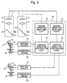
- Fig. 2 is an abstract block diagram of the system of the above goggles.
- Fig. 3 is a perspective view of an LED panel and its driving mechanism.
- Figs. 4A-4C are plan diagrams showing the relationship between the detected gazing direction and the lighting direction.
- Fig. 5 shows a piece of eyeshield of goggles divided into a plurality of sub-areas.
- Fig. 6 is an abstract block diagram of the system of another embodiment of the present invention.
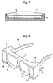
- Fig. 7 is a sectional view of an LED panel of another embodiment of the present invention.
- Fig. 8 is a perspective view of eyeglasses as another embodiment of the present invention.
- Fig. 9 is a front view of goggles as still another embodiment of the present invention.
- Fig. 10 is a side view of the above goggles with a voice controlled gazing point illuminating device.
- Fig. 11 is a view of a conventional surgical operation illuminating system.
- Fig. 1 is a perspective view of an embodiment of the gazing point illuminating device of the present invention and Fig. 2 is an abstract block diagram of its system.
- the gazing point illuminating device of the present embodiment is a pair of goggles 1 for medical use which an operator and staff wear during a surgical operation.
- the goggles 1 of the present embodiment include a headband 3 equipped with an adjuster 2 for fitting the goggles 1 and headband 3 around the wearer's head, and a pair of transparent eyeshields or lenses 4, 4 for the left and right eyes.
- a housing 5, 5 for a light source which will be described later.
- a transparent pane 5a, 5a is fixed at the front of each housing 5, 5.
- eye sensors 7 are provided, whose system is shown in the diagram of Fig. 2.
- a cord 8 is drawn out from one of the housings 5, 5 for connecting the light source, sensor, etc. to a switch and a battery pack (not shown). The switch and the battery pack can be attached to the goggle wearer's clothes or belt.
- the battery pack may be attached to the goggles 1, in which case the cord can be omitted.
- an AC/DC (alternating current to direct current) converter may be used.
- the shape of the panes 5a, 5a may be rectangular, circular or in any other shape, and a light diffuser may be provided in the panes 5a, 5a.
- the gazing directions of the left and right eyes are detected independently, and the lighting directions of left and right light sources housed in the respective housings 5, 5 are automatically controlled independently according to the detected directions of the respective eyes.
- the present embodiment can employ any of such already known gazing direction detectors.
- the Japanese Unexamined Patent Publication No. H8-46833 relates a conventional gazing direction detector as follows. Light from a light source, such as an infrared LED, is cast onto a wearer's eyeball, and the gazing direction of the eye is determined based on the relationship between the reflection of the light by the cornea and the image of the pupil.
- the goggles 1 of the present embodiment use the same type of gazing direction detectors.
- the goggles 1 are equipped with a pair of eye sensors 7 for the left and right eyeballs respectively.
- Each eye sensor 7 includes: an infrared LED 9 for casting infrared light to the eyeball; a dichroic mirror 10 which transmits visible light but reflects infrared light; a lens 11 for converging the infrared light reflected by the dichroic mirror 10; and an image sensor 12 which converts the infrared light converged by the lens 11 into electric signals.
- gazing direction analyzers 13 are provided for the left and right eyes as shown in Fig. 2.
- Each of the gazing direction analyzers 13 determines the gazing point on a piece of eyeshield of the goggles based on the output signal from the corresponding eye sensor 7, or specifically saying, by analyzing the image of the wearer's eyeball taken by the image sensor 12.
- the only difference of the gazing direction detector of the present embodiment from that related in the Japanese Unexamined Patent Publication No. H8-46833 is that the gazing point on the piece of eyeshield of the goggles is detected in the former while that on the finder plate of a camera is detected in the latter.
- the other structure is the same between them so that the detail description can be referred to in the prior art document.
- the light source is an LED panel 15 on which many white LEDs 14 are arrayed two-dimensionally as shown in Fig. 3.
- An LED panel 15 is provided in each of the left and light housings 5, 5.
- a white LED as strong as the luminous intensity of 3 candela is available.
- white LEDs 14 for example, it is possible to illuminate an area of about 50 cm in diameter from about 50 cm distance.
- white LEDs having appropriate directivity are used to intensify the light along the gazing direction.
- the base board of the LED panel 15 may be formed concave to converge the lights of the LEDs 14 to the gazing point.
- the LED panel 15 is rotated vertically and horizontally as shown in Fig. 3. Specifically, the LED panel 15 is rotated by a motor 16 about the horizontal axis (arrow A), and the base plate 17 on which the LED panel 15 and the motor 16 are supported is rotated by a motor 18 about the vertical axis (arrow B).
- a motor 16 and 18 an ultrasonic motor or a stepping motor can be used. Since an LED panel 15 is driven by two motors 16 and 18, there are four motors 16 and 18 in a pair of goggles 1. The four motors 16 and 18 are respectively driven by corresponding driving circuits 19, 19 and 20, 20, as shown in Fig. 2.
- the motors 16 and 18 may be normal rotary motors, or alternatively, ultrasonic motors, piezoelectric motors, or other actuators.
- Lighting direction controllers 21, 21 change the lighting direction of the left and right LED panels 15, 15 by controlling the motors 16, 16 and 18, 18 based on the detected gazing direction of the respective eyes, that is, the output of the gazing direction analyzers 13, 13.
- the gazing direction analyzers 13, 13 and the lighting direction controllers 21, 21 are included in a microcomputer 23.
- Figs. 4A-4C are diagrams showing the relationship between the gazing direction and the lighting direction of an LED panel 15 for an eye 22.
- the entire area of a piece of eyeshield 4 of goggles is divided into a plurality of sub-areas beforehand.
- the piece of eyeshield 4 is divided into nine sub-areas 4 1 -4 9 with three rows by three columns.
- the gazing direction analyzer 13 determines one of the nine sub-areas 4 1 -4 9 where the gazing line penetrates.
- each of the lighting direction controllers 21, 21 nine lighting directions corresponding respectively to the nine sub-areas 4 1 -4 9 are preset.
- Each of the lighting direction controllers 21, 21 brings the lighting direction of the corresponding LED panel 15 to that corresponding to the sub-area determined by the gazing direction analyzer 13.
- the preset lighting directions are explained using Figs. 4A-4C, which illustrate the horizontal plane at the center of a piece of eyeshield 4. It is supposed here, for simplicity, that the gazing line falls in one of the three sub-areas 4 4 , 4 5 , 4 6 in the central row.
- the lighting directions are preset to illuminate a plane S which is distance L apart from the eyeshield 4 of the goggles.
- the distance L may be arbitrarily set, but in case of surgical operation, it is preferable to set the distance L at about 50 cm since the distance between the operator and the part of operation is about 46 cm in a standing operation and about 34 cm in a sitting operation.
- the lighting direction is set so that the LED panel 15 illuminates around the point Sa which is the foot of the gazing line passing through the center of the sub-area 45 on the plane S.
- the lighting direction is set so that the LED panel 15 illuminates around the point Sb which is the foot of the gazing line passing through the center of the sub-area 46 on the plane S.
- the lighting direction is set so that the LED panel 15 illuminates the point Sc which is the foot of the gazing line passing through the center of the sub-area 44 on the plane S.
- the nine lighting directions corresponding to the nine sub-areas 4 1 -4 9 as shown in Fig. 5 are preset. The preset is made for each of the right and left eyes.
- each of the lighting direction controllers 21, 21 for the left and right eyes controls the vertical driving circuit 19 and the horizontal driving circuit 20 to change the orientation of the LED panel 15 to bring the lighting direction of the LED panel 15 to one of the nine preset lighting directions that corresponds to the determined sub-area of the eyeshield 4 based on the output from the corresponding gazing direction analyzer 13.
- the number of sub-areas of a piece of eyeshield 4 may be larger or smaller than nine as shown in Fig. 5. Further, the lighting direction of the LED panel 15 may be changed subtlier according to the coordinates of the point on the piece of eyeshield 4 that the gazing line penetrates.
- the distance L may be other than 50 cm, and further the distance L may be changed according to a distance detected by some distance measuring means.
- the gazing point illuminating device of the present embodiment Since the gazing point illuminating device of the present embodiment is goggles worn on the head, the wearer's shadow is never cast to the part of operation, so that the operator or the staff need not take a clumsy posture during a surgical operation. In addition to that, the illuminating point accords to their gazing point. Different from a conventional illuminating device where a lamp with a fixed lighting direction is worn on the operator's head, the wearer of the illuminating device of the present embodiment does not have to bend his/her head clumsily or unnaturally in order to illuminate a gazing point. This greatly alleviates fatigue and pains on the neck or shoulder of the wearer.
- the light from their goggles 1 jointly illuminate the part, which enables an efficient illumination.
- a conventional astral lighting system which claims a large construction cost and cooling system is no more necessary. Because an LED has a high conversion efficiency, heat production of the light source is reduced and energy is saved. Longlife and low-cost are direct consequences of using LEDs.
- Fig. 6 is a block diagram of the system of another embodiment of the present invention. Same reference numerals are used for the parts corresponding to those in Fig. 2.
- a dimming controller 25 is provided for changing the driving current to the LEDs 14 of the LED panels 15, 15 responsive to a manual control on a control panel 24.
- the illuminance can be controlled by a manual control from the control panel 24. This enables the operator or staff of a surgical operation wearing goggles 1 to change the illuminance at the part of operation according to his/her age, preference or other factors.
- white LEDs are used as the light source.
- a collection of units composed of a red LED, a green LED and a blue LED can be used as the light source.
- RGB LED units red LED, a green LED and a blue LED
- the operator or staff wearing the goggles 1 can manipulate the control panel to change the color so that the color of organs or blood may look more natural.
- the illuminance can also be controlled.
- Ultraviolet LEDs may be added to the light source of white LEDs or that of a collection of RGB LED units.
- the ultraviolet LEDs excite a fluorescent signing attached beforehand on a morbid part such as a tumor, and make the part conspicuously visible.
- Another embodiment of the present invention uses a chip type LED panel.
- a chip type LED panel as described before, many LED chips are placed directly on a surface of a board. Since every LED is not packaged in a cannonball type plastic case, the LEDs can be closely arrayed in an LED panel. Therefore the light source can be made very small and lightweight. If necessary, as shown in Fig. 7, the LED chips 26 of a chip type LED panel 28 may be covered with a lens 27 or a diffuser.
- the present invention is applicable to goggle-type eyeglasses 29 as shown in Fig. 8.
- a zoom mechanism is added to the gazing point illuminating device to zoom in or out the illumination on the part of operation.
- a focus mechanism is added to the gazing point illuminating device to focus the light from the light source to the part of operation or to change the size of the illuminated area.
- the distance to the gazing object is measured beforehand by, for example, using an infrared distance sensor or an ultrasonic distance sensor, and a lens or a group of lenses is driven by a motor in the focus mechanism to focus the light to the gazing object according to the measured distance.
- further light sources may be provided at the space of the upper or lower part of the goggles 4.
- a sole light source at the center of the goggles 4 and illuminate the gazing point at the intersection of the two eyes' gazing lines.
- both eyes' gazing directions are detected independently. Because a person normally gazes an object with both eyes, it is also possible to detect the gazing line of an eye and illuminate the corresponding direction.
- the lighting direction is changed by moving the light source.
- a fixed light source it is possible, with a fixed light source, to provide a lens or lenses in front of the light source, and move the lens or lenses to deflect and change the lighting direction.
- the light source is worn by an operator or staff.
- the light source may be placed at an appropriate place of the operation room, and the operator or staff wear only the gazing direction detector. According to the gazing direction detected by the detector worn by the operator or staff, the lighting direction of the light source placed in the operation room is controlled.
- the device of the present invention is applied in a surgical operation illuminating system.
- the gazing point illuminating device of the present invention can be applied to home medical care purposes such as nursing care. Since the device of the present invention is portable as goggles, it is no more necessary to carry heavy lighting equipments as in a conventional home medical care situation. In such a situation, the diseased part requiring treatment is adequately illuminated by the goggle-type gazing point illuminating device worn by a doctor or nurse.
- a night guard's lighting device a night vision system, a special work requiring a spot light, goggles for fishing or ski at night, an illuminating device for scuba diving, for looking at exhibitions in a museum or plays in a theater, and various uses for entertainment, fashion or art.
- an LED is used as the light source.
- a lamp other than an LED or a semiconductor laser may be used as the light source as well.
- gazing point or gazing line detectors are included.
- the goggles or eyeglasses can be useful gazing point illuminating device by themselves even if they do not include gazing point or direction detectors. That is, a person normally looks straight ahead or his/her gazing direction is normally straight ahead when he/she works. Therefore, except for unusual occasions where he/she purposefully averts his/her gaze, an illuminating device fixed to a person's head for lighting forward is a gazing point illuminating device.
- the goggles provided with an appropriate illuminating device without a gazing point detector or a lighting direction controller can be used as a gazing point illuminating device according to the present invention.
- the power source to the LEDs 52 may be an AC/DC converter connected to the wall socket or a battery worn by the wearer of the goggles or eyeglasses.
- a rechargeable Li-ion battery is preferred in this use whose output voltage (current) can be controlled by a DC-DC converter.
- a manual knob may be provided on a temple of the goggles or glasses.
- a voice control system may be used. The user gives a verbal command (for example, "on”/"off", “up”/”down") through a microphone 53 attached to the goggles, as shown in Fig. 10, to a voice recognition circuit and LED controller incorporated in the goggles or glasses.
- the LED panel or panels when they are attached at both ends of the goggles or eyeglasses
- a small tilting knob or handle may be provided to the frame of the goggles or eyeglasses so that the wearer can easily change the illuminating point according to his position in relation to the gazing object.
- an EL panel can be used.
- the weight of the goggles or goggle-type eyeglasses including such an illuminating device is almost the same as that of an ordinary goggles, so that they can be used as a practical gazing point illuminating device which can be worn for a long time.
- the gazing direction of a user is detected and the lighting direction is changed according to the detected gazing direction, so that the gazing point is automatically illuminated.
- an LED panel composed of a plurality of arrayed LEDs is used as the light source. This decreases heat generation of the light source and the energy consumption is saved compared to conventional incandescent lamps. Another advantage is that it makes the illuminating device of the present invention lightweight and longlife.
- an LED panel composed of red, green and blue LEDs, and adjusting the intensity of every color, the user can obtain an illumination of a desired color.
- the illuminating device of the present invention When the illuminating device of the present invention is used in a surgical operation, the light is automatically directed toward the gazing point of the operator while the operator does not need to take a clumsy posture. This greatly reduces the cost of a surgical operation illuminating system.
- Conventional astral lighting system which claims a high construction cost of the operation room and a large scale cooling system is no more necessary.
- the illuminating device of the present invention When the illuminating device of the present invention is used in a surgical operation or in medical or home care situations, it is possible to adjust the color of the illumination so that the color of the skin, internal organ or blood looks natural.
- ultraviolet LEDs When ultraviolet LEDs are used, further, only a morbid part such as a tumor can be made visible by attaching a fluorescent signing on such a part.
Landscapes
- Engineering & Computer Science (AREA)
- Health & Medical Sciences (AREA)
- Physics & Mathematics (AREA)
- Surgery (AREA)
- General Engineering & Computer Science (AREA)
- Theoretical Computer Science (AREA)
- General Physics & Mathematics (AREA)
- Life Sciences & Earth Sciences (AREA)
- Biomedical Technology (AREA)
- Molecular Biology (AREA)
- Oral & Maxillofacial Surgery (AREA)
- Pathology (AREA)
- Optics & Photonics (AREA)
- Ophthalmology & Optometry (AREA)
- Human Computer Interaction (AREA)
- Heart & Thoracic Surgery (AREA)
- Medical Informatics (AREA)
- Nuclear Medicine, Radiotherapy & Molecular Imaging (AREA)
- Animal Behavior & Ethology (AREA)
- General Health & Medical Sciences (AREA)
- Public Health (AREA)
- Veterinary Medicine (AREA)
- Circuit Arrangement For Electric Light Sources In General (AREA)
- Non-Portable Lighting Devices Or Systems Thereof (AREA)
- Eye Examination Apparatus (AREA)
Applications Claiming Priority (4)
| Application Number | Priority Date | Filing Date | Title |
|---|---|---|---|
| JP2000068696 | 2000-03-13 | ||
| JP2000068696 | 2000-03-13 | ||
| JP2000259771 | 2000-08-29 | ||
| JP2000259771 | 2000-08-29 |
Publications (2)
| Publication Number | Publication Date |
|---|---|
| EP1134491A2 true EP1134491A2 (de) | 2001-09-19 |
| EP1134491A3 EP1134491A3 (de) | 2001-11-21 |
Family
ID=26587317
Family Applications (1)
| Application Number | Title | Priority Date | Filing Date |
|---|---|---|---|
| EP01105730A Withdrawn EP1134491A3 (de) | 2000-03-13 | 2001-03-08 | Vorrichtung zur Beleuchtung einer Blickspitze und System zur Beleuchtung eines chirurgischen Eingriffs mit einer solchen |
Country Status (2)
| Country | Link |
|---|---|
| US (1) | US6554444B2 (de) |
| EP (1) | EP1134491A3 (de) |
Cited By (43)
| Publication number | Priority date | Publication date | Assignee | Title |
|---|---|---|---|---|
| GB2411009A (en) * | 2004-02-13 | 2005-08-17 | Patonlite Spectacles Ltd | Eyewear with one or more light emitting diodes |
| US6974226B2 (en) | 2003-01-30 | 2005-12-13 | Contour Optik, Inc. | Magnetically attachable light assembly for glasses |
| EP1615069A1 (de) * | 2004-07-06 | 2006-01-11 | David Lavoie | Schibrille mit Beleuchtungsvorrichtung |
| US7192136B2 (en) | 2003-04-15 | 2007-03-20 | Howell Thomas A | Tethered electrical components for eyeglasses |
| US7255437B2 (en) | 2003-10-09 | 2007-08-14 | Howell Thomas A | Eyeglasses with activity monitoring |
| DE102006015334A1 (de) * | 2006-04-03 | 2007-10-11 | Ching-Hui Lee | Brille mit eigener Bleuchtung |
| EP1208328B1 (de) * | 1999-09-02 | 2007-10-24 | Bernhard Strehl | Kopfgetragene beleuchtungsvorrichtung |
| EP1633277A4 (de) * | 2003-06-06 | 2007-10-31 | Leto Holdings Llc | Therapeutisches handgerät und verfahren |
| US7380936B2 (en) | 2003-10-09 | 2008-06-03 | Ipventure, Inc. | Eyeglasses with a clock or other electrical component |
| US7438410B1 (en) | 2003-10-09 | 2008-10-21 | Ip Venture, Inc. | Tethered electrical components for eyeglasses |
| US7500747B2 (en) | 2003-10-09 | 2009-03-10 | Ipventure, Inc. | Eyeglasses with electrical components |
| US7500746B1 (en) | 2004-04-15 | 2009-03-10 | Ip Venture, Inc. | Eyewear with radiation detection system |
| US7543934B2 (en) | 2006-09-20 | 2009-06-09 | Ipventures, Inc. | Eyeglasses with activity monitoring and acoustic dampening |
| US7581833B2 (en) | 2003-10-09 | 2009-09-01 | Ipventure, Inc. | Eyewear supporting after-market electrical components |
| US7677723B2 (en) | 2003-10-09 | 2010-03-16 | Ipventure, Inc. | Eyeglasses with a heart rate monitor |
| US7760898B2 (en) | 2003-10-09 | 2010-07-20 | Ip Venture, Inc. | Eyeglasses with hearing enhanced and other audio signal-generating capabilities |
| US7792552B2 (en) | 2003-04-15 | 2010-09-07 | Ipventure, Inc. | Eyeglasses for wireless communications |
| US7806525B2 (en) | 2003-10-09 | 2010-10-05 | Ipventure, Inc. | Eyeglasses having a camera |
| US7922321B2 (en) | 2003-10-09 | 2011-04-12 | Ipventure, Inc. | Eyewear supporting after-market electrical components |
| US8109629B2 (en) | 2003-10-09 | 2012-02-07 | Ipventure, Inc. | Eyewear supporting electrical components and apparatus therefor |
| US8337013B2 (en) | 2004-07-28 | 2012-12-25 | Ipventure, Inc. | Eyeglasses with RFID tags or with a strap |
| US8465151B2 (en) | 2003-04-15 | 2013-06-18 | Ipventure, Inc. | Eyewear with multi-part temple for supporting one or more electrical components |
| EP2314247A4 (de) * | 2008-07-15 | 2016-03-02 | Ltd Liability Company Japan Medical Creative | Beleuchtungsvorrichtung |
| WO2016062642A1 (en) * | 2014-10-21 | 2016-04-28 | Philips Lighting Holding B.V. | System, method and computer program for hands-free configuration of a luminous distribution |
| US9405135B2 (en) | 2011-09-15 | 2016-08-02 | Ipventure, Inc. | Shutter eyewear |
| WO2018100235A1 (en) * | 2016-12-01 | 2018-06-07 | Varjo Technologies Oy | Gaze-tracking system and method |
| US10042186B2 (en) | 2013-03-15 | 2018-08-07 | Ipventure, Inc. | Electronic eyewear and display |
| US10180248B2 (en) | 2015-09-02 | 2019-01-15 | ProPhotonix Limited | LED lamp with sensing capabilities |
| US10310296B2 (en) | 2003-10-09 | 2019-06-04 | Ingeniospec, Llc | Eyewear with printed circuit board |
| US10345625B2 (en) | 2003-10-09 | 2019-07-09 | Ingeniospec, Llc | Eyewear with touch-sensitive input surface |
| WO2020005677A1 (en) * | 2018-06-29 | 2020-01-02 | Osram Gmbh | Lighting devices with automatic lighting adjustment |
| US10624790B2 (en) | 2011-09-15 | 2020-04-21 | Ipventure, Inc. | Electronic eyewear therapy |
| IT201900000809A1 (it) * | 2019-01-18 | 2020-07-18 | Luca Perasole | Dispositivo di illuminazione indossabile e attrezzatura da lavoro che lo comprende |
| US10777048B2 (en) | 2018-04-12 | 2020-09-15 | Ipventure, Inc. | Methods and apparatus regarding electronic eyewear applicable for seniors |
| FR3116135A1 (fr) * | 2020-11-10 | 2022-05-13 | Institut Mines Telecom | Système de capture et du suivi du champ visuel attentionnel et/ou du pilotage du regard d’un individu et/ou la désignation visuelle de cibles. |
| US11513371B2 (en) | 2003-10-09 | 2022-11-29 | Ingeniospec, Llc | Eyewear with printed circuit board supporting messages |
| US11630331B2 (en) | 2003-10-09 | 2023-04-18 | Ingeniospec, Llc | Eyewear with touch-sensitive input surface |
| US11644693B2 (en) | 2004-07-28 | 2023-05-09 | Ingeniospec, Llc | Wearable audio system supporting enhanced hearing support |
| US11733549B2 (en) | 2005-10-11 | 2023-08-22 | Ingeniospec, Llc | Eyewear having removable temples that support electrical components |
| US11829518B1 (en) | 2004-07-28 | 2023-11-28 | Ingeniospec, Llc | Head-worn device with connection region |
| US11852901B2 (en) | 2004-10-12 | 2023-12-26 | Ingeniospec, Llc | Wireless headset supporting messages and hearing enhancement |
| US12044901B2 (en) | 2005-10-11 | 2024-07-23 | Ingeniospec, Llc | System for charging embedded battery in wireless head-worn personal electronic apparatus |
| US12535698B2 (en) | 2005-10-11 | 2026-01-27 | Ingeniospec, Llc | Head-worn structure with fitness monitoring |
Families Citing this family (99)
| Publication number | Priority date | Publication date | Assignee | Title |
|---|---|---|---|---|
| US9167959B1 (en) * | 2010-03-26 | 2015-10-27 | Optech Ventures, Llc | Illumination for enhanced contrast in debridement apparatus and method |
| US7234831B1 (en) * | 2001-04-20 | 2007-06-26 | Hanley Edward B | Headgear with forward illumination |
| US8388164B2 (en) | 2005-05-17 | 2013-03-05 | Michael Waters | Hands-Free lighting devices |
| US8235524B2 (en) * | 2001-11-07 | 2012-08-07 | Michael Waters | Illuminated eyewear |
| US8491118B2 (en) * | 2001-11-07 | 2013-07-23 | Michael Waters | Lighted reading glasses |
| US7661818B2 (en) * | 2001-11-07 | 2010-02-16 | Michael Waters | Clip-on light apparatus |
| US7114823B2 (en) * | 2002-07-19 | 2006-10-03 | Mccullough Wayne | Illumination systems and methods of use |
| GB0222265D0 (en) * | 2002-09-25 | 2002-10-30 | Imp College Innovations Ltd | Control of robotic manipulation |
| US6824265B1 (en) | 2003-03-31 | 2004-11-30 | Wesley Stephen Harper | Illuminated safety and work glasses |
| US6969178B2 (en) * | 2003-10-14 | 2005-11-29 | Steven Zuloff | Portable black light device |
| US6966668B2 (en) * | 2003-11-07 | 2005-11-22 | Noah Systems, Llc | Wearable light device with optical sensor |
| US6955444B2 (en) * | 2003-11-12 | 2005-10-18 | Visiled, Inc. | Surgical headlight |
| EP1568938B1 (de) * | 2004-02-28 | 2006-09-27 | TRUMPF Kreuzer Medizin Systeme GmbH + Co. KG | Operationsleuchte |
| DE102004053128A1 (de) * | 2004-07-16 | 2006-02-09 | Osram Opto Semiconductors Gmbh | Sportbrille mit erhöhter Sichtbarkeit |
| US9526292B2 (en) | 2005-05-17 | 2016-12-27 | Michael Waters | Power modules and headgear |
| US8979295B2 (en) | 2005-05-17 | 2015-03-17 | Michael Waters | Rechargeable lighted glasses |
| DE102005036275A1 (de) * | 2005-08-02 | 2007-02-08 | Berchtold Holding Gmbh | Operationsleuchte |
| US7291852B1 (en) | 2005-08-17 | 2007-11-06 | Infinite Innovations Inc. Of John A. Matlack Only | Lighting system, point source lights therefor and methods of making the same |
| PL1785665T3 (pl) * | 2005-11-14 | 2012-03-30 | Trumpf Medizin Systeme Gmbh & Co Kg | Lampa operacyjna |
| SE0600392L (sv) * | 2006-02-23 | 2006-11-28 | Laszlo Kormos | Lysanordning för dykare |
| US8197539B2 (en) | 2006-05-05 | 2012-06-12 | University Of Southern California | Intraocular camera for retinal prostheses |
| GB0609662D0 (en) * | 2006-05-16 | 2006-06-28 | Fryett David H | Flashing swimming goggles |
| DE202007007054U1 (de) * | 2006-11-15 | 2007-07-26 | Trumpf Kreuzer Medizin Systeme Gmbh + Co. Kg | System mit einer Operationsleuchte und mit einer Kamera |
| US7370991B1 (en) | 2006-12-18 | 2008-05-13 | Ellis-Fant Wanda J | Voice-controlled surgical lighting assembly |
| US20080297716A1 (en) * | 2007-06-01 | 2008-12-04 | Tsai Tien-Chun | Eyeglasses structure |
| US7699486B1 (en) * | 2007-10-29 | 2010-04-20 | Edward Beiner | Illuminated eyeglass assembly |
| USD583850S1 (en) * | 2007-12-18 | 2008-12-30 | Waleed Jabali | Combination binocular, eyeglasses, and adjustable headband assembly |
| US8550651B2 (en) | 2007-12-18 | 2013-10-08 | Waters Industries, Inc. | Lighted hat |
| US20090214436A1 (en) | 2008-02-18 | 2009-08-27 | Washington University | Dichromic fluorescent compounds |
| EP2382503A2 (de) * | 2008-12-30 | 2011-11-02 | Focus Brite, LLC | Beleuchtetes optisches gerät |
| CN101950091B (zh) | 2009-09-30 | 2014-01-22 | 迈克尔·沃特斯 | 照明眼镜 |
| US20120206660A1 (en) * | 2009-12-01 | 2012-08-16 | Sharp Kabushiki Kaisha | Light source package, illumination device, display device, and television receiving device |
| AU2011215777B2 (en) * | 2010-02-10 | 2015-11-26 | Michael Waters | Illuminated eyewear |
| US8746914B2 (en) | 2010-02-15 | 2014-06-10 | Webb T. Nelson | Sports set that utilize stereoscopic illumination and retroreflective materials |
| US8550649B2 (en) * | 2010-02-15 | 2013-10-08 | Webb T. Nelson | Stereoscopic illumination system for retroreflective materials |
| US9091851B2 (en) | 2010-02-28 | 2015-07-28 | Microsoft Technology Licensing, Llc | Light control in head mounted displays |
| US9129295B2 (en) | 2010-02-28 | 2015-09-08 | Microsoft Technology Licensing, Llc | See-through near-eye display glasses with a fast response photochromic film system for quick transition from dark to clear |
| US9128281B2 (en) | 2010-09-14 | 2015-09-08 | Microsoft Technology Licensing, Llc | Eyepiece with uniformly illuminated reflective display |
| US9285589B2 (en) | 2010-02-28 | 2016-03-15 | Microsoft Technology Licensing, Llc | AR glasses with event and sensor triggered control of AR eyepiece applications |
| US9366862B2 (en) | 2010-02-28 | 2016-06-14 | Microsoft Technology Licensing, Llc | System and method for delivering content to a group of see-through near eye display eyepieces |
| WO2011106797A1 (en) | 2010-02-28 | 2011-09-01 | Osterhout Group, Inc. | Projection triggering through an external marker in an augmented reality eyepiece |
| US9097890B2 (en) | 2010-02-28 | 2015-08-04 | Microsoft Technology Licensing, Llc | Grating in a light transmissive illumination system for see-through near-eye display glasses |
| US9341843B2 (en) | 2010-02-28 | 2016-05-17 | Microsoft Technology Licensing, Llc | See-through near-eye display glasses with a small scale image source |
| US20120249797A1 (en) | 2010-02-28 | 2012-10-04 | Osterhout Group, Inc. | Head-worn adaptive display |
| US8467133B2 (en) | 2010-02-28 | 2013-06-18 | Osterhout Group, Inc. | See-through display with an optical assembly including a wedge-shaped illumination system |
| US9223134B2 (en) | 2010-02-28 | 2015-12-29 | Microsoft Technology Licensing, Llc | Optical imperfections in a light transmissive illumination system for see-through near-eye display glasses |
| US9759917B2 (en) | 2010-02-28 | 2017-09-12 | Microsoft Technology Licensing, Llc | AR glasses with event and sensor triggered AR eyepiece interface to external devices |
| US8488246B2 (en) | 2010-02-28 | 2013-07-16 | Osterhout Group, Inc. | See-through near-eye display glasses including a curved polarizing film in the image source, a partially reflective, partially transmitting optical element and an optically flat film |
| US8477425B2 (en) | 2010-02-28 | 2013-07-02 | Osterhout Group, Inc. | See-through near-eye display glasses including a partially reflective, partially transmitting optical element |
| US20150309316A1 (en) | 2011-04-06 | 2015-10-29 | Microsoft Technology Licensing, Llc | Ar glasses with predictive control of external device based on event input |
| US9134534B2 (en) | 2010-02-28 | 2015-09-15 | Microsoft Technology Licensing, Llc | See-through near-eye display glasses including a modular image source |
| US9097891B2 (en) | 2010-02-28 | 2015-08-04 | Microsoft Technology Licensing, Llc | See-through near-eye display glasses including an auto-brightness control for the display brightness based on the brightness in the environment |
| US9229227B2 (en) | 2010-02-28 | 2016-01-05 | Microsoft Technology Licensing, Llc | See-through near-eye display glasses with a light transmissive wedge shaped illumination system |
| US10180572B2 (en) | 2010-02-28 | 2019-01-15 | Microsoft Technology Licensing, Llc | AR glasses with event and user action control of external applications |
| US9182596B2 (en) | 2010-02-28 | 2015-11-10 | Microsoft Technology Licensing, Llc | See-through near-eye display glasses with the optical assembly including absorptive polarizers or anti-reflective coatings to reduce stray light |
| US8482859B2 (en) | 2010-02-28 | 2013-07-09 | Osterhout Group, Inc. | See-through near-eye display glasses wherein image light is transmitted to and reflected from an optically flat film |
| US8472120B2 (en) | 2010-02-28 | 2013-06-25 | Osterhout Group, Inc. | See-through near-eye display glasses with a small scale image source |
| USD663036S1 (en) | 2010-04-16 | 2012-07-03 | Creative Casts, LLC | Cast inlay |
| CN202975580U (zh) | 2010-04-30 | 2013-06-05 | 迈克尔·沃特斯 | 头部装备和安装在帽子上的摄像机装置 |
| US8427014B2 (en) | 2010-05-11 | 2013-04-23 | The Invention Science Fund I, Llc | System including wearable power receiver and wearable power-output device |
| US7946705B1 (en) * | 2010-06-30 | 2011-05-24 | Sun And Young Sunglasses Co., Ltd. | Rechargeable illuminated eyeglasses |
| US8540364B2 (en) | 2010-09-14 | 2013-09-24 | Michael Waters | Lighted glasses |
| BR112013008003A2 (pt) | 2010-10-08 | 2016-06-14 | Koninkl Philips Electronics Nv | óculos de proteção para prover feedback, sistema para prover feedback e método para prover feedback |
| KR101114993B1 (ko) * | 2011-02-28 | 2012-03-06 | (재)예수병원유지재단 | 눈 위치를 추적하는 의료용 헤드램프 |
| US8188880B1 (en) * | 2011-03-14 | 2012-05-29 | Google Inc. | Methods and devices for augmenting a field of view |
| KR101046677B1 (ko) * | 2011-03-15 | 2011-07-06 | 동국대학교 산학협력단 | 눈 위치 추적방법 및 이를 이용한 의료용 헤드램프 |
| US8813268B1 (en) | 2011-09-05 | 2014-08-26 | Outdoor Cap Company, Inc. | Lighted headwear with recessed light source and lens |
| US9568173B2 (en) | 2011-12-23 | 2017-02-14 | Michael Waters | Lighted hat |
| USD682343S1 (en) | 2011-12-23 | 2013-05-14 | Michael Waters | Lighted glasses |
| US9526287B2 (en) | 2011-12-23 | 2016-12-27 | Michael Waters | Lighted hat |
| US9609902B2 (en) | 2011-12-23 | 2017-04-04 | Michael Waters | Headgear having a camera device |
| EP2806781B1 (de) | 2012-01-23 | 2018-03-21 | Washington University | Brillenbildgebungssysteme und -verfahren |
| USD660902S1 (en) | 2012-02-02 | 2012-05-29 | Hasbro, Inc. | Vision apparatus |
| WO2014100477A1 (en) | 2012-12-19 | 2014-06-26 | Michael Waters | Lighted solar hat |
| US9717633B2 (en) | 2013-03-15 | 2017-08-01 | Michael Waters | Lighted headgear |
| USD770143S1 (en) | 2014-05-23 | 2016-11-01 | Michael Waters | Beanie with means for illumination |
| US10069318B2 (en) | 2014-12-02 | 2018-09-04 | Michael Waters | LED flashlight with longitudinal cooling fins |
| USD824557S1 (en) | 2014-12-02 | 2018-07-31 | Michael Waters | Flashlight |
| US10806804B2 (en) | 2015-05-06 | 2020-10-20 | Washington University | Compounds having RD targeting motifs and methods of use thereof |
| SE539801C2 (sv) * | 2015-07-28 | 2017-12-05 | Lensk | Ljusram för visir samt svetshjälm |
| USD801418S1 (en) * | 2015-11-13 | 2017-10-31 | 3Optics Co., Ltd. | Glasses for watching stereoscopic images |
| US9851074B2 (en) | 2016-04-15 | 2017-12-26 | Enova Illumination, LLC | Surgical illuminator |
| KR102786412B1 (ko) | 2016-09-22 | 2025-03-25 | 매직 립, 인코포레이티드 | 증강 현실 분광기 |
| US10139652B2 (en) * | 2016-10-14 | 2018-11-27 | Randy Lee Windham | Eyeluminators |
| WO2019183399A1 (en) | 2018-03-21 | 2019-09-26 | Magic Leap, Inc. | Augmented reality system and method for spectroscopic analysis |
| US10791783B1 (en) | 2019-05-16 | 2020-10-06 | Waters Industries, Inc. | Lighted headgear and accessories therefor |
| US11611705B1 (en) * | 2019-06-10 | 2023-03-21 | Julian W. Chen | Smart glasses with augmented reality capability for dentistry |
| US11071497B2 (en) * | 2019-06-11 | 2021-07-27 | Gentex Corporation | Wearable medical device |
| US20210149222A1 (en) * | 2019-11-14 | 2021-05-20 | Jay Emirzian | Dental Shade-Matching Device |
| EP3826432A1 (de) | 2019-11-22 | 2021-05-26 | Oberalp Spa | Scheinwerfer mit al-einheit |
| US11009222B1 (en) | 2019-12-09 | 2021-05-18 | Patrick James Sevigny | Lighting apparatus and method of use |
| US11712482B2 (en) | 2019-12-13 | 2023-08-01 | Washington University | Near infrared fluorescent dyes, formulations and related methods |
| USD994757S1 (en) | 2020-08-20 | 2023-08-08 | Nicholas Kral | Illuminated bar for eyeglasses |
| US20220128840A1 (en) * | 2020-10-27 | 2022-04-28 | Michael Peterson | Costume Eyeglass Assembly |
| US11350506B1 (en) | 2021-05-03 | 2022-05-31 | Ober Alp S.P.A. | Adaptive illumination control via activity classification |
| US12413325B2 (en) * | 2021-10-04 | 2025-09-09 | Snap Inc. | Synchronizing systems on a chip using time synchronization messages |
| US12021611B2 (en) | 2021-10-07 | 2024-06-25 | Snap Inc. | Synchronizing systems-on-chip using GPIO timestamps |
| US12171293B2 (en) | 2021-12-27 | 2024-12-24 | Waters Industries, Inc. | Lighted headgear and accessories therefor |
| USD1045965S1 (en) | 2022-01-05 | 2024-10-08 | Gentex Corporation | Eyewear |
Family Cites Families (20)
| Publication number | Priority date | Publication date | Assignee | Title |
|---|---|---|---|---|
| US4234910A (en) * | 1978-03-20 | 1980-11-18 | Price Linda D | Head-supported illumination device |
| US4254451A (en) | 1978-10-27 | 1981-03-03 | Cochran James A Jun | Sequential flashing device for personal ornamentation |
| JPS56156022A (en) | 1980-05-06 | 1981-12-02 | Oki Electric Ind Co Ltd | E/dmos semiconductor device |
| JPS5944042B2 (ja) | 1980-07-17 | 1984-10-26 | 三菱電機株式会社 | ジユ−サ− |
| US4616257A (en) * | 1985-06-13 | 1986-10-07 | Luxtec Corporation | Headlight |
| US4759615A (en) * | 1986-06-09 | 1988-07-26 | American Sterilizer Company | Illumination system using amplified polarized light |
| US6014524A (en) | 1988-03-23 | 2000-01-11 | Canon Kabushiki Kaisha | Camera with visual axis detecting device |
| JPH067702U (ja) | 1991-07-15 | 1994-02-01 | 伸子 滝本 | 診察用眼鏡及び眼鏡に使用する診察用照明装置 |
| US5289355A (en) * | 1993-01-08 | 1994-02-22 | I & K Trading | Portable lighted microphone |
| US5355285A (en) * | 1993-01-12 | 1994-10-11 | Hicks John W | Surgeon's headlight system |
| US5430620A (en) | 1993-10-08 | 1995-07-04 | Cogent Light Technologies, Inc. | Compact surgical illumination system capable of dynamically adjusting the resulting field of illumination |
| JPH0846833A (ja) | 1994-07-29 | 1996-02-16 | Canon Inc | 視線検出機能付カメラ |
| US5671996A (en) * | 1994-12-30 | 1997-09-30 | Donnelly Corporation | Vehicle instrumentation/console lighting |
| US5778384A (en) | 1995-12-22 | 1998-07-07 | Sun Microsystems, Inc. | System and method for automounting and accessing remote file systems in Microsoft Windows in a networking environment |
| US5722762A (en) | 1996-07-18 | 1998-03-03 | Soll; David B. | Illumination device for mounting on the head of a user |
| JP3049423B2 (ja) | 1997-09-24 | 2000-06-05 | 重則 常岡 | 甲殻類の加工食品及びその製造方法、及びその加工食品を使用した調理品の製造方法 |
| GB9813041D0 (en) | 1998-06-16 | 1998-08-12 | Scient Generics Ltd | Eye tracking technique |
| JP2000039595A (ja) | 1998-07-24 | 2000-02-08 | Katsuyoshi Naito | ライト付きメガネ |
| US6224227B1 (en) * | 1999-10-20 | 2001-05-01 | Jack Klootz | Surgical headlight assembly with detachable video-camera module |
| US6390640B1 (en) * | 2000-07-06 | 2002-05-21 | American Underwater Products Inc. | Lighted mask for underwater divers |
-
2001
- 2001-03-06 US US09/798,982 patent/US6554444B2/en not_active Expired - Fee Related
- 2001-03-08 EP EP01105730A patent/EP1134491A3/de not_active Withdrawn
Non-Patent Citations (1)
| Title |
|---|
| None |
Cited By (91)
| Publication number | Priority date | Publication date | Assignee | Title |
|---|---|---|---|---|
| EP1208328B1 (de) * | 1999-09-02 | 2007-10-24 | Bernhard Strehl | Kopfgetragene beleuchtungsvorrichtung |
| US6974226B2 (en) | 2003-01-30 | 2005-12-13 | Contour Optik, Inc. | Magnetically attachable light assembly for glasses |
| US7792552B2 (en) | 2003-04-15 | 2010-09-07 | Ipventure, Inc. | Eyeglasses for wireless communications |
| US7192136B2 (en) | 2003-04-15 | 2007-03-20 | Howell Thomas A | Tethered electrical components for eyeglasses |
| US9690121B2 (en) | 2003-04-15 | 2017-06-27 | Ingeniospec, Llc | Eyewear supporting one or more electrical components |
| US12078870B2 (en) | 2003-04-15 | 2024-09-03 | Ingeniospec, Llc | Eyewear housing for charging embedded battery in eyewear frame |
| US8465151B2 (en) | 2003-04-15 | 2013-06-18 | Ipventure, Inc. | Eyewear with multi-part temple for supporting one or more electrical components |
| US10252079B2 (en) | 2003-06-06 | 2019-04-09 | Koninklijke Philips N.V. | Hand-held light therapy apparatus |
| EP1633277A4 (de) * | 2003-06-06 | 2007-10-31 | Leto Holdings Llc | Therapeutisches handgerät und verfahren |
| US9138595B2 (en) | 2003-06-06 | 2015-09-22 | Koninklijke Philips N.V. | Hand-held programmable ocular light therapy apparatus and methods |
| US7481531B2 (en) | 2003-10-09 | 2009-01-27 | Ipventure, Inc. | Eyeglasses with user monitoring |
| US8434863B2 (en) | 2003-10-09 | 2013-05-07 | Thomas A. Howell | Eyeglasses with a printed circuit board |
| US7500747B2 (en) | 2003-10-09 | 2009-03-10 | Ipventure, Inc. | Eyeglasses with electrical components |
| US11803069B2 (en) | 2003-10-09 | 2023-10-31 | Ingeniospec, Llc | Eyewear with connection region |
| US11762224B2 (en) | 2003-10-09 | 2023-09-19 | Ingeniospec, Llc | Eyewear having extended endpieces to support electrical components |
| US7581833B2 (en) | 2003-10-09 | 2009-09-01 | Ipventure, Inc. | Eyewear supporting after-market electrical components |
| US7621634B2 (en) | 2003-10-09 | 2009-11-24 | Ipventure, Inc. | Tethered electrical components for eyeglasses |
| US7677723B2 (en) | 2003-10-09 | 2010-03-16 | Ipventure, Inc. | Eyeglasses with a heart rate monitor |
| US7760898B2 (en) | 2003-10-09 | 2010-07-20 | Ip Venture, Inc. | Eyeglasses with hearing enhanced and other audio signal-generating capabilities |
| US7771046B2 (en) | 2003-10-09 | 2010-08-10 | I p Venture, Inc. | Eyewear with monitoring capability |
| US7438410B1 (en) | 2003-10-09 | 2008-10-21 | Ip Venture, Inc. | Tethered electrical components for eyeglasses |
| US7806525B2 (en) | 2003-10-09 | 2010-10-05 | Ipventure, Inc. | Eyeglasses having a camera |
| US11630331B2 (en) | 2003-10-09 | 2023-04-18 | Ingeniospec, Llc | Eyewear with touch-sensitive input surface |
| US7922321B2 (en) | 2003-10-09 | 2011-04-12 | Ipventure, Inc. | Eyewear supporting after-market electrical components |
| US8109629B2 (en) | 2003-10-09 | 2012-02-07 | Ipventure, Inc. | Eyewear supporting electrical components and apparatus therefor |
| US11536988B2 (en) | 2003-10-09 | 2022-12-27 | Ingeniospec, Llc | Eyewear supporting embedded electronic components for audio support |
| US8430507B2 (en) | 2003-10-09 | 2013-04-30 | Thomas A. Howell | Eyewear with touch-sensitive input surface |
| US10061144B2 (en) | 2003-10-09 | 2018-08-28 | Ingeniospec, Llc | Eyewear supporting embedded electronic components |
| US7401918B2 (en) | 2003-10-09 | 2008-07-22 | Ipventure, Inc. | Eyeglasses with activity monitoring |
| US8500271B2 (en) | 2003-10-09 | 2013-08-06 | Ipventure, Inc. | Eyewear supporting after-market electrical components |
| US11513371B2 (en) | 2003-10-09 | 2022-11-29 | Ingeniospec, Llc | Eyewear with printed circuit board supporting messages |
| US8905542B2 (en) | 2003-10-09 | 2014-12-09 | Ingeniospec, Llc | Eyewear supporting bone conducting speaker |
| US9033493B2 (en) | 2003-10-09 | 2015-05-19 | Ingeniospec, Llc | Eyewear supporting electrical components and apparatus therefor |
| US7380936B2 (en) | 2003-10-09 | 2008-06-03 | Ipventure, Inc. | Eyeglasses with a clock or other electrical component |
| US11243416B2 (en) | 2003-10-09 | 2022-02-08 | Ingeniospec, Llc | Eyewear supporting embedded electronic components |
| US11204512B2 (en) | 2003-10-09 | 2021-12-21 | Ingeniospec, Llc | Eyewear supporting embedded and tethered electronic components |
| US11086147B2 (en) | 2003-10-09 | 2021-08-10 | Ingeniospec, Llc | Eyewear supporting electrical components and apparatus therefor |
| US10345625B2 (en) | 2003-10-09 | 2019-07-09 | Ingeniospec, Llc | Eyewear with touch-sensitive input surface |
| US9547184B2 (en) | 2003-10-09 | 2017-01-17 | Ingeniospec, Llc | Eyewear supporting embedded electronic components |
| US7255437B2 (en) | 2003-10-09 | 2007-08-14 | Howell Thomas A | Eyeglasses with activity monitoring |
| US10330956B2 (en) | 2003-10-09 | 2019-06-25 | Ingeniospec, Llc | Eyewear supporting electrical components and apparatus therefor |
| US10310296B2 (en) | 2003-10-09 | 2019-06-04 | Ingeniospec, Llc | Eyewear with printed circuit board |
| US12164180B2 (en) | 2003-10-09 | 2024-12-10 | Ingeniospec, Llc | Eyewear supporting distributed and embedded electronic components |
| GB2411009A (en) * | 2004-02-13 | 2005-08-17 | Patonlite Spectacles Ltd | Eyewear with one or more light emitting diodes |
| US10060790B2 (en) | 2004-04-12 | 2018-08-28 | Ingeniospec, Llc | Eyewear with radiation detection system |
| US9488520B2 (en) | 2004-04-12 | 2016-11-08 | Ingeniospec, Llc | Eyewear with radiation detection system |
| US10539459B2 (en) | 2004-04-15 | 2020-01-21 | Ingeniospec, Llc | Eyewear with detection system |
| US7500746B1 (en) | 2004-04-15 | 2009-03-10 | Ip Venture, Inc. | Eyewear with radiation detection system |
| US11644361B2 (en) | 2004-04-15 | 2023-05-09 | Ingeniospec, Llc | Eyewear with detection system |
| US10359311B2 (en) | 2004-04-15 | 2019-07-23 | Ingeniospec, Llc | Eyewear with radiation detection system |
| US8770742B2 (en) | 2004-04-15 | 2014-07-08 | Ingeniospec, Llc | Eyewear with radiation detection system |
| US11326941B2 (en) | 2004-04-15 | 2022-05-10 | Ingeniospec, Llc | Eyewear with detection system |
| EP1615069A1 (de) * | 2004-07-06 | 2006-01-11 | David Lavoie | Schibrille mit Beleuchtungsvorrichtung |
| US11921355B2 (en) | 2004-07-28 | 2024-03-05 | Ingeniospec, Llc | Head-worn personal audio apparatus supporting enhanced hearing support |
| US12025855B2 (en) | 2004-07-28 | 2024-07-02 | Ingeniospec, Llc | Wearable audio system supporting enhanced hearing support |
| US11644693B2 (en) | 2004-07-28 | 2023-05-09 | Ingeniospec, Llc | Wearable audio system supporting enhanced hearing support |
| US8337013B2 (en) | 2004-07-28 | 2012-12-25 | Ipventure, Inc. | Eyeglasses with RFID tags or with a strap |
| US11829518B1 (en) | 2004-07-28 | 2023-11-28 | Ingeniospec, Llc | Head-worn device with connection region |
| US12238494B1 (en) | 2004-07-28 | 2025-02-25 | Ingeniospec, Llc | Head-worn device with connection region |
| US12140819B1 (en) | 2004-07-28 | 2024-11-12 | Ingeniospec, Llc | Head-worn personal audio apparatus supporting enhanced audio output |
| US12001599B2 (en) | 2004-07-28 | 2024-06-04 | Ingeniospec, Llc | Head-worn device with connection region |
| US11852901B2 (en) | 2004-10-12 | 2023-12-26 | Ingeniospec, Llc | Wireless headset supporting messages and hearing enhancement |
| US12242138B1 (en) | 2004-10-12 | 2025-03-04 | Ingeniospec, Llc | Wireless headset supporting messages and hearing enhancement |
| US12248198B2 (en) | 2005-10-11 | 2025-03-11 | Ingeniospec, Llc | Eyewear having flexible printed circuit substrate supporting electrical components |
| US12044901B2 (en) | 2005-10-11 | 2024-07-23 | Ingeniospec, Llc | System for charging embedded battery in wireless head-worn personal electronic apparatus |
| US11733549B2 (en) | 2005-10-11 | 2023-08-22 | Ingeniospec, Llc | Eyewear having removable temples that support electrical components |
| US12313913B1 (en) | 2005-10-11 | 2025-05-27 | Ingeniospec, Llc | System for powering head-worn personal electronic apparatus |
| US12345955B2 (en) | 2005-10-11 | 2025-07-01 | Ingeniospec, Llc | Head-worn eyewear structure with internal fan |
| US12535698B2 (en) | 2005-10-11 | 2026-01-27 | Ingeniospec, Llc | Head-worn structure with fitness monitoring |
| DE102006015334A1 (de) * | 2006-04-03 | 2007-10-11 | Ching-Hui Lee | Brille mit eigener Bleuchtung |
| DE102006015334B4 (de) * | 2006-04-03 | 2010-11-25 | Ching-Hui Lee | Brille mit eigener Bleuchtung |
| US7543934B2 (en) | 2006-09-20 | 2009-06-09 | Ipventures, Inc. | Eyeglasses with activity monitoring and acoustic dampening |
| EP2314247A4 (de) * | 2008-07-15 | 2016-03-02 | Ltd Liability Company Japan Medical Creative | Beleuchtungsvorrichtung |
| US9405135B2 (en) | 2011-09-15 | 2016-08-02 | Ipventure, Inc. | Shutter eyewear |
| US10624790B2 (en) | 2011-09-15 | 2020-04-21 | Ipventure, Inc. | Electronic eyewear therapy |
| US11042045B2 (en) | 2013-03-15 | 2021-06-22 | Ingeniospec, Llc | Electronic eyewear and display |
| US10042186B2 (en) | 2013-03-15 | 2018-08-07 | Ipventure, Inc. | Electronic eyewear and display |
| US10539788B2 (en) | 2014-10-21 | 2020-01-21 | Signify Holding B.V. | System, method and computer program for hands-free configuration of a luminous distribution |
| CN107077013A (zh) * | 2014-10-21 | 2017-08-18 | 飞利浦灯具控股公司 | 用于发光分布的不用手配置的系统、方法和计算机程序产品 |
| WO2016062642A1 (en) * | 2014-10-21 | 2016-04-28 | Philips Lighting Holding B.V. | System, method and computer program for hands-free configuration of a luminous distribution |
| US10180248B2 (en) | 2015-09-02 | 2019-01-15 | ProPhotonix Limited | LED lamp with sensing capabilities |
| US10395111B2 (en) | 2016-12-01 | 2019-08-27 | Varjo Technologies Oy | Gaze-tracking system and method |
| WO2018100235A1 (en) * | 2016-12-01 | 2018-06-07 | Varjo Technologies Oy | Gaze-tracking system and method |
| US11721183B2 (en) | 2018-04-12 | 2023-08-08 | Ingeniospec, Llc | Methods and apparatus regarding electronic eyewear applicable for seniors |
| US10777048B2 (en) | 2018-04-12 | 2020-09-15 | Ipventure, Inc. | Methods and apparatus regarding electronic eyewear applicable for seniors |
| WO2020005677A1 (en) * | 2018-06-29 | 2020-01-02 | Osram Gmbh | Lighting devices with automatic lighting adjustment |
| US10667366B2 (en) | 2018-06-29 | 2020-05-26 | Osram Sylvania Inc. | Lighting devices with automatic lighting adjustment |
| EP3682839A1 (de) * | 2019-01-18 | 2020-07-22 | Perasole, Luca | Tragbares beleuchtungsgerät und das gerätumfassende arbeitsausrüstung |
| IT201900000809A1 (it) * | 2019-01-18 | 2020-07-18 | Luca Perasole | Dispositivo di illuminazione indossabile e attrezzatura da lavoro che lo comprende |
| WO2022101136A1 (fr) * | 2020-11-10 | 2022-05-19 | Institut Mines Telecom | Systeme de capture et du suivi du champ visuel attentionnel et/ou du pilotage du regard d'un individu et/ou la designation visuelle de cibles. |
| FR3116135A1 (fr) * | 2020-11-10 | 2022-05-13 | Institut Mines Telecom | Système de capture et du suivi du champ visuel attentionnel et/ou du pilotage du regard d’un individu et/ou la désignation visuelle de cibles. |
Also Published As
| Publication number | Publication date |
|---|---|
| US6554444B2 (en) | 2003-04-29 |
| EP1134491A3 (de) | 2001-11-21 |
| US20010021108A1 (en) | 2001-09-13 |
Similar Documents
| Publication | Publication Date | Title |
|---|---|---|
| US6554444B2 (en) | Gazing point illuminating device | |
| US7614763B2 (en) | Operating table lamp | |
| JP4452607B2 (ja) | 照明装置、フィルタ装置、画像表示装置 | |
| US6955444B2 (en) | Surgical headlight | |
| US20050099824A1 (en) | Methods and systems for medical lighting | |
| US8789962B2 (en) | Surgical headlight | |
| WO2003019072A9 (en) | Color temperature-regulable led light | |
| JP2015035373A (ja) | 照明ユニット及び医療用照明装置 | |
| JP2002150803A (ja) | 視線照明装置及び手術照明システム | |
| US20020089844A1 (en) | Lamp device which is worn on the head | |
| KR20150015507A (ko) | 낙농 축사에서 사용하기 위한 led 조명기구 | |
| US12443056B2 (en) | Eyewear with circumambient illumination | |
| JP3648802B2 (ja) | 光治療用高照度光照射装置 | |
| CN206534765U (zh) | 一种全光谱色彩疗养眼罩 | |
| JP2013541977A (ja) | 頭部装着型光線療法 | |
| JP2002324403A (ja) | 視野照明装置 | |
| CN107166216A (zh) | 一种多功能护眼led灯 | |
| KR102574519B1 (ko) | 의료용 조명 장치 및 조명 시스템 | |
| CN106402776A (zh) | 一种照明设备 | |
| CN212691541U (zh) | 全光谱台灯 | |
| JP6390998B2 (ja) | 照明器具及びそれを用いた医療器具 | |
| CN107477411A (zh) | 一种防护视力的夜间阅读灯 | |
| US12540721B2 (en) | Modular, universal, and standalone eyewear circumambient illumination kits and systems | |
| CN209529471U (zh) | 提供眼底照明的玻璃体切割镜头环 | |
| WO2025230750A1 (en) | Eyewear with circumambient illumination |
Legal Events
| Date | Code | Title | Description |
|---|---|---|---|
| PUAI | Public reference made under article 153(3) epc to a published international application that has entered the european phase |
Free format text: ORIGINAL CODE: 0009012 |
|
| AK | Designated contracting states |
Kind code of ref document: A2 Designated state(s): DE FR GB Kind code of ref document: A2 Designated state(s): AT BE CH CY DE DK ES FI FR GB GR IE IT LI LU MC NL PT SE TR |
|
| AX | Request for extension of the european patent |
Free format text: AL;LT;LV;MK;RO;SI |
|
| PUAL | Search report despatched |
Free format text: ORIGINAL CODE: 0009013 |
|
| AK | Designated contracting states |
Kind code of ref document: A3 Designated state(s): AT BE CH CY DE DK ES FI FR GB GR IE IT LI LU MC NL PT SE TR |
|
| AX | Request for extension of the european patent |
Free format text: AL;LT;LV;MK;RO;SI |
|
| 17P | Request for examination filed |
Effective date: 20020316 |
|
| AKX | Designation fees paid |
Free format text: DE FR GB |
|
| STAA | Information on the status of an ep patent application or granted ep patent |
Free format text: STATUS: THE APPLICATION HAS BEEN WITHDRAWN |
|
| 18W | Application withdrawn |
Effective date: 20060222 |