EP1138434A1 - Elektrisch betriebene vorrichtung für ein greifer - Google Patents
Elektrisch betriebene vorrichtung für ein greifer Download PDFInfo
- Publication number
- EP1138434A1 EP1138434A1 EP01400728A EP01400728A EP1138434A1 EP 1138434 A1 EP1138434 A1 EP 1138434A1 EP 01400728 A EP01400728 A EP 01400728A EP 01400728 A EP01400728 A EP 01400728A EP 1138434 A1 EP1138434 A1 EP 1138434A1
- Authority
- EP
- European Patent Office
- Prior art keywords
- motor
- key
- orifice
- shaft
- toothed wheel
- Prior art date
- Legal status (The legal status is an assumption and is not a legal conclusion. Google has not performed a legal analysis and makes no representation as to the accuracy of the status listed.)
- Granted
Links
Images




Classifications
-
- H—ELECTRICITY
- H02—GENERATION; CONVERSION OR DISTRIBUTION OF ELECTRIC POWER
- H02K—DYNAMO-ELECTRIC MACHINES
- H02K7/00—Arrangements for handling mechanical energy structurally associated with dynamo-electric machines, e.g. structural association with mechanical driving motors or auxiliary dynamo-electric machines
- H02K7/06—Means for converting reciprocating motion into rotary motion or vice versa
-
- B—PERFORMING OPERATIONS; TRANSPORTING
- B23—MACHINE TOOLS; METAL-WORKING NOT OTHERWISE PROVIDED FOR
- B23K—SOLDERING OR UNSOLDERING; WELDING; CLADDING OR PLATING BY SOLDERING OR WELDING; CUTTING BY APPLYING HEAT LOCALLY, e.g. FLAME CUTTING; WORKING BY LASER BEAM
- B23K11/00—Resistance welding; Severing by resistance heating
- B23K11/30—Features relating to electrodes
- B23K11/31—Electrode holders and actuating devices therefor
- B23K11/311—Electrode holders and actuating devices therefor the actuating device comprising an electric motor
-
- B—PERFORMING OPERATIONS; TRANSPORTING
- B23—MACHINE TOOLS; METAL-WORKING NOT OTHERWISE PROVIDED FOR
- B23K—SOLDERING OR UNSOLDERING; WELDING; CLADDING OR PLATING BY SOLDERING OR WELDING; CUTTING BY APPLYING HEAT LOCALLY, e.g. FLAME CUTTING; WORKING BY LASER BEAM
- B23K11/00—Resistance welding; Severing by resistance heating
- B23K11/30—Features relating to electrodes
- B23K11/31—Electrode holders and actuating devices therefor
- B23K11/314—Spot welding guns, e.g. mounted on robots
- B23K11/315—Spot welding guns, e.g. mounted on robots with one electrode moving on a linear path
Definitions
- the present invention relates to a device for electric motorization for tool pliers, of the type comprising an electric motor casing whose shaft is connected to the clamp, for opening control of tools carried by articulated arms, of their closure and tightening them on a workpiece, by a system of transformation, of the type passing through the engine, of a rotary movement of the shaft in a movement of translation of an actuating member of the clamp, this motor being associated with a coupled servo member to the motor rotor, themselves connected to a dimmer ordered.
- welding tongs it could be for example a clamp whose arms supporting the electrodes are of the so-called "C” type or type called “scissors", being in any case necessary, for controlling the movements of this clamp, welding or other, to transform, by a screw-nut system or analogous, the rotation of the motor shaft in one movement of translation of an actuating member of the clamp.
- the control dimmer mentioned above has function of supplying the motor with current for the set in rotation during the dynamic phases of movement of the tool support arms (opening or clamp closure) and, in static phase, for him exercise a couple, transformed by said system of transformation of movement into a clamping force of tools on the part, for example a sheet metal to be welded.
- the aforesaid servo member of the type analog (resolver) or digital (encoder), it is coupled to the motor rotor and has the function of inform the control variator of the position and speed of the motor rotor, and thereby ensure the enslavement.
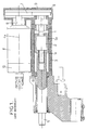
- the axis la of screw 1 in taken with a nut 2 movable in translation in the body 3 of the device, is parallel to the axis 4a of the engine electric 4.
- the clamp actuator not shown, is referenced in 5 and is linked kinematics with the nut 2 by the part 5a.
- the output shaft 6 of the motor 4 must be connected to the head of screw 1 by a transmission system of any rotary movement, for example with gears or toothed belt and pulleys, as was globally referenced in 7. From this conception results the fact that one can have easy access to the head of the screw 1, at the end box 8, after having extracts its closure cap 9.
- this type of construction presents the disadvantages of requiring a large number of parts, to be of significant weight and bulk on a welding machine, and to be expensive.
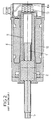
- the system is directly integrated screw - nut to the motor: here nut 2 is movable in rotation and is therefore directly integral with the rotor 11 of the motor 4, the stator of which is referenced 12.
- the screw 1 in taken with this nut and axially movable in translation in motor 4, has an outgoing end 5 constituting the actuating member of the clamp.
- the object of the present invention is to remedy all these disadvantages of the prior art, and therefore to obtain convenient access to the motor shaft for the rotate and thus move manually in translation the actuator of the clamp, at least fresh and without increasing the size or weight of equipment.
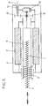
- a device as defined at the beginning is, according to the invention, of the type with transformation of rotary movement into movement of translation passing through the engine and is characterized in that that said servo member coupled to the rotor of the motor being placed at the end of the motor shaft, the shaft is provided with an externally actuated toothed wheel, for its manual rotation, through an orifice casing offset from said shaft.
- Said gear can be conical, and the axis of said orifice form an angle with the axis of the motor, for example an angle of 90 °.
- said toothed wheel is cylindrical and is engaged with a cylindrical pinion actuable through said hole, the axis of said hole can then be parallel to the axis of the engine.
- said toothed wheel will be put in rotation by a key, this key being able to bring to its end a toothing which can mesh with said wheel.
- said motor housing contains a toothing operable through said orifice and suitable for be rotated by the key and at the same time to be brought into engagement with said end gear shaft, the disengagement between said toothing and the wheel toothed taking place, when removing the key, under the effect of a spring or inertia.
- said motor housing contains a toothing actuable through said orifice and suitable for being put in rotation by the key, this toothing being engaged permanent with said gear.
- teeth involved may be of any suitable type, for example straight, helical, inclined, or rack and pinion unending.
- the toothing 16 could be permanently housed in the bottom of port 15, be there kept in the free position by a return spring or by its inertia, and be brought into engagement with the wheel toothed 14 only when introduced into the orifice 15 of a key without teeth but profiled to make turn the teeth 16 and thus drive the wheel 14 in rotation; this toothing could also be engaged permanent with the gear 14.
- FIG. 6 shows the variant according to which the motor housing 4 contains a cylindrical toothing 16 actuable through the orifice 15 and suitable for being put in rotation by a key similar to key 17 but without teeth, and at the same time to be brought into engagement with the cylindrical gear 14 of the shaft end.
- the disengagement between the teeth 16 and the gear 14 takes place when the key is removed, under the effect of a spring 19.
- FIG. 7 describes the variant according to which motor housing 4 contains a conical toothing 16, also suitable for being rotated by a key, this toothing being in permanent engagement with the wheel conical tooth 14 of the motor shaft and being mounted for this reason in a bearing 20 of the orifice 15.
Landscapes
- Engineering & Computer Science (AREA)
- Mechanical Engineering (AREA)
- Power Engineering (AREA)
- Robotics (AREA)
- Connection Of Motors, Electrical Generators, Mechanical Devices, And The Like (AREA)
- Manipulator (AREA)
- Yarns And Mechanical Finishing Of Yarns Or Ropes (AREA)
- Formation And Processing Of Food Products (AREA)
- Transmission Devices (AREA)
- Jigs For Machine Tools (AREA)
- Dental Tools And Instruments Or Auxiliary Dental Instruments (AREA)
- Resistance Welding (AREA)
- Hand Tools For Fitting Together And Separating, Or Other Hand Tools (AREA)
- Gripping Jigs, Holding Jigs, And Positioning Jigs (AREA)
- Advancing Webs (AREA)
Applications Claiming Priority (2)
| Application Number | Priority Date | Filing Date | Title |
|---|---|---|---|
| FR0004122A FR2806951B1 (fr) | 2000-03-31 | 2000-03-31 | Dispositif de motorisation electrique pour pince d'outillage |
| FR0004122 | 2000-03-31 |
Publications (2)
| Publication Number | Publication Date |
|---|---|
| EP1138434A1 true EP1138434A1 (de) | 2001-10-04 |
| EP1138434B1 EP1138434B1 (de) | 2006-05-31 |
Family
ID=8848718
Family Applications (1)
| Application Number | Title | Priority Date | Filing Date |
|---|---|---|---|
| EP01400728A Expired - Lifetime EP1138434B1 (de) | 2000-03-31 | 2001-03-21 | Elektrisch betriebene Vorrichtung für einen Greifer |
Country Status (10)
| Country | Link |
|---|---|
| US (1) | US6479783B2 (de) |
| EP (1) | EP1138434B1 (de) |
| JP (1) | JP2001328041A (de) |
| AT (1) | ATE327861T1 (de) |
| CA (1) | CA2342286A1 (de) |
| CZ (1) | CZ20011064A3 (de) |
| DE (1) | DE60120022T2 (de) |
| ES (1) | ES2266129T3 (de) |
| FR (1) | FR2806951B1 (de) |
| SK (1) | SK3582001A3 (de) |
Cited By (5)
| Publication number | Priority date | Publication date | Assignee | Title |
|---|---|---|---|---|
| WO2003066269A3 (de) * | 2002-02-05 | 2003-12-11 | Swac Electronic Gmbh | Antriebsvorrichtung für eine schweisszange |
| CN103231259A (zh) * | 2013-04-02 | 2013-08-07 | 华南理工大学 | 一种用于模具电极加工的通用t型夹具 |
| CN108381433A (zh) * | 2018-05-30 | 2018-08-10 | 珠海格力智能装备有限公司 | 定心机构 |
| CN108462305A (zh) * | 2018-01-29 | 2018-08-28 | 浙江捷昌线性驱动科技股份有限公司 | 一种线性致动器 |
| CN117548962A (zh) * | 2023-12-27 | 2024-02-13 | 合肥永升机械有限公司 | 一种挖掘机下车架焊接工装及其使用方法 |
Families Citing this family (5)
| Publication number | Priority date | Publication date | Assignee | Title |
|---|---|---|---|---|
| FR2903034B1 (fr) * | 2006-07-03 | 2009-04-10 | Aro Soc Par Actions Simplifiee | Pince a enserrer des toles, utilisee en association avec un bras manipulateur, et a module d'equilibrage electromecanique |
| US20130190714A1 (en) | 2012-01-19 | 2013-07-25 | Tekni-Plex, Inc | Multi-layered tubing |
| DE102017112448A1 (de) * | 2017-06-06 | 2018-12-06 | Arnold & Shinjo Gmbh & Co. Kg | Vorrichtung und Verfahren zur Herstellung eines Bauteilverbunds sowie Kraftfahrzeug |
| CN113726090B (zh) * | 2021-08-10 | 2023-12-08 | 锐迈科技股份有限公司 | 一种电机驱动结构及电机驱动装置 |
| CN115912777B (zh) * | 2022-12-30 | 2025-09-09 | 南京拓耘达智慧科技有限公司 | 一种精巧型直行程电动执行机构 |
Citations (3)
| Publication number | Priority date | Publication date | Assignee | Title |
|---|---|---|---|---|
| US3802713A (en) * | 1972-03-22 | 1974-04-09 | Burnerd F And Co Ltd | Lever operated collet chuck |
| DE19749681A1 (de) * | 1996-11-12 | 1998-05-14 | Luk Getriebe Systeme Gmbh | Kraftfahrzeug mit einer Vorrichtung zur Betätigung eines Getriebes und/oder einer Kupplung |
| EP0924038A2 (de) * | 1997-12-01 | 1999-06-23 | Black & Decker Inc. | Werkzeugeinspannvorrichtung für ein angetriebenes Werkzeug |
Family Cites Families (17)
| Publication number | Priority date | Publication date | Assignee | Title |
|---|---|---|---|---|
| US3744032A (en) * | 1971-07-15 | 1973-07-03 | Unimotion Inc | Stationary base programmed manipulator arrangement for continuously moving workpiece |
| DE3105105C2 (de) * | 1981-02-12 | 1984-05-17 | Kuka Schweissanlagen + Roboter Gmbh, 8900 Augsburg | Haltevorrichtung für bewegliche Schweißwerkzeuge mit einem Drehanschluß für die Beschickung des Werkzeuges |
| US4485959A (en) * | 1982-05-14 | 1984-12-04 | Gnb Batteries Inc. | Means for welding intercell connections |
| GB8321376D0 (en) * | 1983-08-09 | 1983-09-28 | British Aerospace | Control apparatus |
| JPS62198852A (ja) * | 1986-02-27 | 1987-09-02 | Japan Synthetic Rubber Co Ltd | ポジ型感放射線性樹脂組成物 |
| JP3136865B2 (ja) * | 1993-10-27 | 2001-02-19 | トヨタ自動車株式会社 | スポット溶接の溶着解除方法およびスポット溶接装置 |
| JPH06226457A (ja) * | 1993-02-08 | 1994-08-16 | Mazda Motor Corp | 溶接装置 |
| JPH0787722A (ja) * | 1993-09-13 | 1995-03-31 | Oriental Motor Co Ltd | リニアモータ |
| JP3695784B2 (ja) * | 1995-03-08 | 2005-09-14 | Smc株式会社 | 電動アクチュエータ |
| US5924518A (en) * | 1996-07-24 | 1999-07-20 | Trw Inc. | Linear drive electric assist steering system |
| US6075298A (en) * | 1997-10-09 | 2000-06-13 | Lear Automotive Dearborn, Inc | Rotary and linear translation actuator performing multi-functions in an automobile |
| US6204585B1 (en) * | 1997-12-19 | 2001-03-20 | Riello Macchine Transfer Srl | Work unit having an integrally mounted drive unit |
| US6084326A (en) * | 1998-02-04 | 2000-07-04 | Smc Kabushiki Kaisha | Actuator |
| US6081051A (en) * | 1998-05-13 | 2000-06-27 | Sanyo Denki Co., Ltd. | Linear/rotary actuator and winding machine including same |
| US6225590B1 (en) * | 1998-05-26 | 2001-05-01 | Medar, Inc. | Method for determining a condition of a resistance spotwelding system or a workpiece in the system |
| BR9804426A (pt) * | 1998-10-16 | 2000-05-16 | Elevadores Atlas S A | Máquina elétrica de relutância subsìncrona. |
| US6337456B1 (en) * | 1998-12-16 | 2002-01-08 | Dengensha Manufacturing Company Limited | Welding machine and method for assembling same |
-
2000
- 2000-03-31 FR FR0004122A patent/FR2806951B1/fr not_active Expired - Lifetime
-
2001
- 2001-03-14 SK SK358-2001A patent/SK3582001A3/sk unknown
- 2001-03-21 AT AT01400728T patent/ATE327861T1/de not_active IP Right Cessation
- 2001-03-21 EP EP01400728A patent/EP1138434B1/de not_active Expired - Lifetime
- 2001-03-21 ES ES01400728T patent/ES2266129T3/es not_active Expired - Lifetime
- 2001-03-21 DE DE60120022T patent/DE60120022T2/de not_active Expired - Lifetime
- 2001-03-23 CZ CZ20011064A patent/CZ20011064A3/cs unknown
- 2001-03-27 CA CA002342286A patent/CA2342286A1/en not_active Abandoned
- 2001-03-30 JP JP2001102155A patent/JP2001328041A/ja active Pending
- 2001-03-30 US US09/821,153 patent/US6479783B2/en not_active Expired - Lifetime
Patent Citations (3)
| Publication number | Priority date | Publication date | Assignee | Title |
|---|---|---|---|---|
| US3802713A (en) * | 1972-03-22 | 1974-04-09 | Burnerd F And Co Ltd | Lever operated collet chuck |
| DE19749681A1 (de) * | 1996-11-12 | 1998-05-14 | Luk Getriebe Systeme Gmbh | Kraftfahrzeug mit einer Vorrichtung zur Betätigung eines Getriebes und/oder einer Kupplung |
| EP0924038A2 (de) * | 1997-12-01 | 1999-06-23 | Black & Decker Inc. | Werkzeugeinspannvorrichtung für ein angetriebenes Werkzeug |
Cited By (6)
| Publication number | Priority date | Publication date | Assignee | Title |
|---|---|---|---|---|
| WO2003066269A3 (de) * | 2002-02-05 | 2003-12-11 | Swac Electronic Gmbh | Antriebsvorrichtung für eine schweisszange |
| US7435924B2 (en) | 2002-02-05 | 2008-10-14 | Swac Electronic Gmbh | Drive device for welding tongs |
| CN103231259A (zh) * | 2013-04-02 | 2013-08-07 | 华南理工大学 | 一种用于模具电极加工的通用t型夹具 |
| CN108462305A (zh) * | 2018-01-29 | 2018-08-28 | 浙江捷昌线性驱动科技股份有限公司 | 一种线性致动器 |
| CN108381433A (zh) * | 2018-05-30 | 2018-08-10 | 珠海格力智能装备有限公司 | 定心机构 |
| CN117548962A (zh) * | 2023-12-27 | 2024-02-13 | 合肥永升机械有限公司 | 一种挖掘机下车架焊接工装及其使用方法 |
Also Published As
| Publication number | Publication date |
|---|---|
| US6479783B2 (en) | 2002-11-12 |
| CZ20011064A3 (cs) | 2002-03-13 |
| FR2806951B1 (fr) | 2002-06-14 |
| JP2001328041A (ja) | 2001-11-27 |
| FR2806951A1 (fr) | 2001-10-05 |
| ATE327861T1 (de) | 2006-06-15 |
| DE60120022D1 (de) | 2006-07-06 |
| EP1138434B1 (de) | 2006-05-31 |
| ES2266129T3 (es) | 2007-03-01 |
| SK3582001A3 (en) | 2001-10-08 |
| US20020014474A1 (en) | 2002-02-07 |
| CA2342286A1 (en) | 2001-09-30 |
| DE60120022T2 (de) | 2007-01-04 |
Similar Documents
| Publication | Publication Date | Title |
|---|---|---|
| EP1138434B1 (de) | Elektrisch betriebene Vorrichtung für einen Greifer | |
| FR2812612A1 (fr) | Derailleur avant motorise de bicyclette | |
| FR2743764A1 (fr) | Mecanisme d'articulation pour siege de vehicule, et siege comportant un tel mecanisme | |
| CH646892A5 (fr) | Procede de decoupage par decharges electriques. | |
| EP0074883A1 (de) | Vorrichtung zur Übertragung geradliniger Bewegungen mittels Riemenscheiben und Treibriemen | |
| FR2703728A1 (fr) | Dispositif pour modifier les paliers de rotation d'un arbre de commande qui commande une soupape d'échange des gaz d'un moteur thermique . | |
| FR2881175A1 (fr) | Commande de reglage de distribution variable de soupapes | |
| FR2546387A1 (fr) | Ferrure d'articulation pour sieges a dossier reglable, notamment des sieges de vehicules automobiles | |
| EP1370388A1 (de) | Vorrichtung zum antreiben und damit hergestelltes spannwerkeug | |
| FR2965878A1 (fr) | Boite de vitesses pour equipement de motoculture et equipement de motoculture comprenant une telle boite de vitesses | |
| FR2711932A1 (fr) | Dispositif porte-outil, notamment tête de fraisage, à porte-broche orientable. | |
| FR2687338A1 (fr) | Tete de fraisage perfectionnee. | |
| FR2539204A1 (fr) | Vanne motorisee a deux ou trois voies | |
| WO2004059110A1 (fr) | Procede de commande d'une serrure electrique munie d'un embrayage | |
| EP1122031A1 (de) | Spann-Wekzeug und insbesondere Krimp-Wekzeug | |
| EP0240438A1 (de) | Robotergelenk | |
| FR2631872A1 (fr) | Tete revolver pour machine-outil | |
| EP1702691A1 (de) | Vorrichtung zum Biegen und Ziehen | |
| FR2470658A1 (fr) | Appareil a cle oleodynamique de serrage servant a devisser et a serrer des ecrous | |
| EP0064422B1 (de) | Ferngesteuerte Einrichtung für einen Fahrzeugrückblickspiegel | |
| FR2792872A1 (fr) | Groupe d'impression d'une machine a imprimer rotative | |
| FR2723545A1 (fr) | Poignee articulee pour la main de travail d'un robot | |
| FR2633863A1 (fr) | Robot manipulateur a deplacement horizontal circulaire | |
| FR2463661A1 (fr) | Dispositif d'avance mu a | |
| EP1132228A1 (de) | Belüftungsanlage des Fahrgastraums eines Kraftfahrzeugs |
Legal Events
| Date | Code | Title | Description |
|---|---|---|---|
| PUAI | Public reference made under article 153(3) epc to a published international application that has entered the european phase |
Free format text: ORIGINAL CODE: 0009012 |
|
| AK | Designated contracting states |
Kind code of ref document: A1 Designated state(s): AT BE CH CY DE DK ES FI FR GB GR IE IT LI LU MC NL PT SE TR |
|
| AX | Request for extension of the european patent |
Free format text: AL;LT;LV;MK;RO;SI |
|
| 17P | Request for examination filed |
Effective date: 20020311 |
|
| AKX | Designation fees paid |
Free format text: AT BE CH CY DE DK ES FI FR GB GR IE IT LI LU MC NL PT SE TR |
|
| GRAP | Despatch of communication of intention to grant a patent |
Free format text: ORIGINAL CODE: EPIDOSNIGR1 |
|
| RTI1 | Title (correction) |
Free format text: ELECTRICALLY-POWERED EQUIPMENT FOR A GRIPPER |
|
| GRAS | Grant fee paid |
Free format text: ORIGINAL CODE: EPIDOSNIGR3 |
|
| GRAA | (expected) grant |
Free format text: ORIGINAL CODE: 0009210 |
|
| AK | Designated contracting states |
Kind code of ref document: B1 Designated state(s): AT BE CH CY DE DK ES FI FR GB GR IE IT LI LU MC NL PT SE TR |
|
| PG25 | Lapsed in a contracting state [announced via postgrant information from national office to epo] |
Ref country code: IT Free format text: LAPSE BECAUSE OF FAILURE TO SUBMIT A TRANSLATION OF THE DESCRIPTION OR TO PAY THE FEE WITHIN THE PRESCRIBED TIME-LIMIT;WARNING: LAPSES OF ITALIAN PATENTS WITH EFFECTIVE DATE BEFORE 2007 MAY HAVE OCCURRED AT ANY TIME BEFORE 2007. THE CORRECT EFFECTIVE DATE MAY BE DIFFERENT FROM THE ONE RECORDED. Effective date: 20060531 Ref country code: IE Free format text: LAPSE BECAUSE OF FAILURE TO SUBMIT A TRANSLATION OF THE DESCRIPTION OR TO PAY THE FEE WITHIN THE PRESCRIBED TIME-LIMIT Effective date: 20060531 Ref country code: NL Free format text: LAPSE BECAUSE OF FAILURE TO SUBMIT A TRANSLATION OF THE DESCRIPTION OR TO PAY THE FEE WITHIN THE PRESCRIBED TIME-LIMIT Effective date: 20060531 Ref country code: AT Free format text: LAPSE BECAUSE OF FAILURE TO SUBMIT A TRANSLATION OF THE DESCRIPTION OR TO PAY THE FEE WITHIN THE PRESCRIBED TIME-LIMIT Effective date: 20060531 Ref country code: FI Free format text: LAPSE BECAUSE OF FAILURE TO SUBMIT A TRANSLATION OF THE DESCRIPTION OR TO PAY THE FEE WITHIN THE PRESCRIBED TIME-LIMIT Effective date: 20060531 |
|
| REG | Reference to a national code |
Ref country code: GB Ref legal event code: FG4D Free format text: NOT ENGLISH Ref country code: CH Ref legal event code: EP |
|
| REG | Reference to a national code |
Ref country code: IE Ref legal event code: FG4D Free format text: LANGUAGE OF EP DOCUMENT: FRENCH |
|
| REF | Corresponds to: |
Ref document number: 60120022 Country of ref document: DE Date of ref document: 20060706 Kind code of ref document: P |
|
| PG25 | Lapsed in a contracting state [announced via postgrant information from national office to epo] |
Ref country code: DK Free format text: LAPSE BECAUSE OF FAILURE TO SUBMIT A TRANSLATION OF THE DESCRIPTION OR TO PAY THE FEE WITHIN THE PRESCRIBED TIME-LIMIT Effective date: 20060831 |
|
| REG | Reference to a national code |
Ref country code: SE Ref legal event code: TRGR |
|
| GBT | Gb: translation of ep patent filed (gb section 77(6)(a)/1977) |
Effective date: 20060904 |
|
| PG25 | Lapsed in a contracting state [announced via postgrant information from national office to epo] |
Ref country code: PT Free format text: LAPSE BECAUSE OF FAILURE TO SUBMIT A TRANSLATION OF THE DESCRIPTION OR TO PAY THE FEE WITHIN THE PRESCRIBED TIME-LIMIT Effective date: 20061031 |
|
| NLV1 | Nl: lapsed or annulled due to failure to fulfill the requirements of art. 29p and 29m of the patents act | ||
| REG | Reference to a national code |
Ref country code: IE Ref legal event code: FD4D |
|
| REG | Reference to a national code |
Ref country code: ES Ref legal event code: FG2A Ref document number: 2266129 Country of ref document: ES Kind code of ref document: T3 |
|
| PLBE | No opposition filed within time limit |
Free format text: ORIGINAL CODE: 0009261 |
|
| STAA | Information on the status of an ep patent application or granted ep patent |
Free format text: STATUS: NO OPPOSITION FILED WITHIN TIME LIMIT |
|
| 26N | No opposition filed |
Effective date: 20070301 |
|
| REG | Reference to a national code |
Ref country code: CH Ref legal event code: PL |
|
| BERE | Be: lapsed |
Owner name: ARO Effective date: 20070331 |
|
| PG25 | Lapsed in a contracting state [announced via postgrant information from national office to epo] |
Ref country code: BE Free format text: LAPSE BECAUSE OF NON-PAYMENT OF DUE FEES Effective date: 20070331 |
|
| PG25 | Lapsed in a contracting state [announced via postgrant information from national office to epo] |
Ref country code: MC Free format text: LAPSE BECAUSE OF NON-PAYMENT OF DUE FEES Effective date: 20070331 |
|
| PG25 | Lapsed in a contracting state [announced via postgrant information from national office to epo] |
Ref country code: LI Free format text: LAPSE BECAUSE OF NON-PAYMENT OF DUE FEES Effective date: 20070331 Ref country code: CH Free format text: LAPSE BECAUSE OF NON-PAYMENT OF DUE FEES Effective date: 20070331 |
|
| PG25 | Lapsed in a contracting state [announced via postgrant information from national office to epo] |
Ref country code: GR Free format text: LAPSE BECAUSE OF FAILURE TO SUBMIT A TRANSLATION OF THE DESCRIPTION OR TO PAY THE FEE WITHIN THE PRESCRIBED TIME-LIMIT Effective date: 20060901 |
|
| PG25 | Lapsed in a contracting state [announced via postgrant information from national office to epo] |
Ref country code: LU Free format text: LAPSE BECAUSE OF NON-PAYMENT OF DUE FEES Effective date: 20070321 Ref country code: CY Free format text: LAPSE BECAUSE OF FAILURE TO SUBMIT A TRANSLATION OF THE DESCRIPTION OR TO PAY THE FEE WITHIN THE PRESCRIBED TIME-LIMIT Effective date: 20060531 |
|
| PG25 | Lapsed in a contracting state [announced via postgrant information from national office to epo] |
Ref country code: TR Free format text: LAPSE BECAUSE OF FAILURE TO SUBMIT A TRANSLATION OF THE DESCRIPTION OR TO PAY THE FEE WITHIN THE PRESCRIBED TIME-LIMIT Effective date: 20060531 |
|
| REG | Reference to a national code |
Ref country code: FR Ref legal event code: PLFP Year of fee payment: 15 |
|
| REG | Reference to a national code |
Ref country code: FR Ref legal event code: PLFP Year of fee payment: 16 |
|
| REG | Reference to a national code |
Ref country code: FR Ref legal event code: PLFP Year of fee payment: 17 |
|
| REG | Reference to a national code |
Ref country code: FR Ref legal event code: PLFP Year of fee payment: 18 |
|
| PGFP | Annual fee paid to national office [announced via postgrant information from national office to epo] |
Ref country code: DE Payment date: 20200311 Year of fee payment: 20 Ref country code: GB Payment date: 20200323 Year of fee payment: 20 Ref country code: IT Payment date: 20200312 Year of fee payment: 20 Ref country code: SE Payment date: 20200327 Year of fee payment: 20 |
|
| PGFP | Annual fee paid to national office [announced via postgrant information from national office to epo] |
Ref country code: FR Payment date: 20200127 Year of fee payment: 20 |
|
| PGFP | Annual fee paid to national office [announced via postgrant information from national office to epo] |
Ref country code: ES Payment date: 20200423 Year of fee payment: 20 |
|
| REG | Reference to a national code |
Ref country code: DE Ref legal event code: R071 Ref document number: 60120022 Country of ref document: DE |
|
| REG | Reference to a national code |
Ref country code: GB Ref legal event code: PE20 Expiry date: 20210320 |
|
| PG25 | Lapsed in a contracting state [announced via postgrant information from national office to epo] |
Ref country code: GB Free format text: LAPSE BECAUSE OF EXPIRATION OF PROTECTION Effective date: 20210320 |
|
| REG | Reference to a national code |
Ref country code: SE Ref legal event code: EUG |
|
| REG | Reference to a national code |
Ref country code: ES Ref legal event code: FD2A Effective date: 20220126 |
|
| PG25 | Lapsed in a contracting state [announced via postgrant information from national office to epo] |
Ref country code: ES Free format text: LAPSE BECAUSE OF EXPIRATION OF PROTECTION Effective date: 20210322 |