EP1138447A2 - Werkbank für Arbeiten an metallischen Tür- und Fensterrahmen sowie anderen sperrigen Gegenständen - Google Patents
Werkbank für Arbeiten an metallischen Tür- und Fensterrahmen sowie anderen sperrigen Gegenständen Download PDFInfo
- Publication number
- EP1138447A2 EP1138447A2 EP01830203A EP01830203A EP1138447A2 EP 1138447 A2 EP1138447 A2 EP 1138447A2 EP 01830203 A EP01830203 A EP 01830203A EP 01830203 A EP01830203 A EP 01830203A EP 1138447 A2 EP1138447 A2 EP 1138447A2
- Authority
- EP
- European Patent Office
- Prior art keywords
- sliding
- base frame
- beams
- bench
- tracks
- Prior art date
- Legal status (The legal status is an assumption and is not a legal conclusion. Google has not performed a legal analysis and makes no representation as to the accuracy of the status listed.)
- Withdrawn
Links
Images


Classifications
-
- B—PERFORMING OPERATIONS; TRANSPORTING
- B25—HAND TOOLS; PORTABLE POWER-DRIVEN TOOLS; MANIPULATORS
- B25H—WORKSHOP EQUIPMENT, e.g. FOR MARKING-OUT WORK; STORAGE MEANS FOR WORKSHOPS
- B25H1/00—Work benches; Portable stands or supports for positioning portable tools or work to be operated on thereby
- B25H1/14—Work benches; Portable stands or supports for positioning portable tools or work to be operated on thereby with provision for adjusting the bench top
Definitions
- This bench offers limited capacity for increasing the useable surface area for supporting the items being handled.
- the present bench is of the type that comprises a base frame and supports that can be extended from said base frame to increase the surface area that can be used for working on.
- the bench comprises, on the base frame, pairs of longitudinal tracks for extending, from opposite sides of the base frame, supporting beams with end legs, such as to obtain - with said extendable beams - an increase in the surface area on each side of the base frame of the same order of magnitude as the dimension of the base frame in the direction of extension.
- the bench may also comprise sliding tracks perpendicular to the previous tracks, for the lateral extension of a sliding assembly from one edge or from each edge of the base frame, in which case said sliding assembly or each of said sliding assemblies similarly has a pair of longitudinal tracks for extending supporting beams with end legs by corresponding amounts on opposite sides of said sliding assembly.
- Both the extendable beams and the sliding assembly or assemblies have legs capable of sliding or rolling on the floor.
- Said base frame - and, if present, said sliding assembly or assemblies - may possess fixed sections forming two opposite tracks, each of said sections being able to guide two beams along its opposite sides for extension in opposite directions.
- the fixed sections and the beams may have the same cross section.
- each sliding beam is a sliding shoe, and attached to the corresponding track is a supporting shoe; said two shoes work together to facilitate sliding and to act as stops at the position of maximum extension of the associated beam.
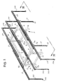
- the number 1 is a general reference for a fixed base frame which comprises two end trusses 1A forming supporting crossmembers 1 B at the top, on which more later; 1C denotes longitudinal connecting members between the two trusses 1A.
- the whole frame 1 is fixed and capable of forming sliding tracks for the expansion of the supporting surface area relative to the horizontal area occupied by said frame 1.
- a track section 3 creating two opposite longitudinal sliding tracks is fixed to the frame 1.
- two slides 5 capable of being adjusted in position along the crossmembers 1 B.
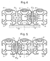
- the two slides 5 support a second track section 7 with two opposite sliding tracks 7A and 7B (see in particular Figs 4 and 5).
- the two crossmembers 1 B also create transverse sliding tracks for a sliding assembly that can be extended at right angles to the direction of the sliding tracks 3 and 7, which sliding assembly may in practice consist of two channel sections 9 and a third track section 11 that forms two longitudinal tracks similar to the tracks 7A and 7B already described.
- the bench comprises two pairs of longitudinal tracks formed by section 3, section 7 and section 11; section 3 is fixed to the frame 1, section 7 is adjustable in position by means of the slides 5 along the crossmembers 1B of the frame 1, and section 11 is extendable at right angles to the direction of extension of the tracks 3, 7 and 11, said section 11 forming part of the sliding assembly 9, 11 which extends laterally in the direction of arrow fE shown in Figs 1 and 2.
- the channel sections 9 of the sliding assembly 9, 11 are advantageously equipped at their ends with uprights 13 with casters 15 to support them as they move across the floor and provide stability to the sliding assembly 9, 11.
- Each of the sections 3, 7 and 11 incorporates two tracks such as the tracks 7A, 7B of section 7, and is flanked by two supporting beams marked 31 and 33 (those of track section 3), 71 and 73 (those flanking track section 7) and 111 and 113 (those flanking track section 11).
- Each of these beams 31, 33; 71, 73 and 111, 113 is supported, at the extending end-by an upright 313, 333; 713, 733; 1113, 1133 with respective casters such as the casters 315, 715 and 1115 at the ends of said beams 31, 71 and 111.
- the beams 31, 33; 71, 73; 111, 113 can be composed of sections exactly like those of the pairs of longitudinal tracks 3, 7 and 11, of which the tracks 7 are more particularly shown in Figs 4 and 5. These sections are now described with reference to the sections 71, 73, to which the sections 31, 33 and 111, 113 are equivalent.
- the extendable beams 71 and 73 possess sliding tracks 71A and 73A which correspond to and are opposed to the sliding tracks 7A and 7B of the section 7.
- the beam 71 formed by the section illustrated in Figs 4 and 5, similar to the section 7, can be slid longitudinally in the direction of arrow f71 and the beam 73 formed by a similar section like the section 7 can be slid longitudinally in the direction of arrow f73, in the opposite direction to the beam 71.
- the beams 31 and 33 on the one hand, and the beams 111 and 113 on the other, can likewise be extended to create extensions in the direction indicated by the axes of the beams 3, 7 and 11 to increase the length of the longitudinal supports represented by the sections 3, 7, 11 by as much as three times.
- the tracks represented by sections 7 and 11 can be kept close together on top of the crossmembers 1B of the frame 1, or can be displaced in the transverse direction, that is in the direction of arrow fE by differing amounts in order to increase in the direction of arrow fE the supporting area represented by the sections described above; in particular, by appropriately distributing the supports, the sections 71, 7 and 73 with the slides 5 can be moved half as far as the transversely sliding assembly 9, 11 which creates the supports by means of the sections 111,11 and 113.
- Each shoe is indicated as a whole by the number 81 and comprises a separating wall 81A, two sliding seats 81B, 81E, two locking seats 81 C and 81 F and a retaining wall 81 G which can be tightened using tightening screws 83.
- the shoes such as the shoes 81 described above are clamped to the inward ends of the moveable beams and to the ends of the fixed beams forming the double sliding track such as 3, 7 and 11, from which ends the beams are pulled out.
- the distance between the shoes of the sections e.g. such as 7 and 71, which are fixed in positions 81X of beam 71 and 81Y of beam 7, is the residual length where the sections 7 and 71 are side by side.
- the shoes 81 positioned for example as indicated at 81X and 81Y in the case of beams 7 and 71, act as stops to define the maximum extension of the beam 71 from the track 7A of the section 7; and likewise for all the other shoes.
- the sections 3, 7, 11 and the beams 31, 33; 71, 73; 111, 113 can be provided with protective surface trims as indicated at 91 in Figs 4 and 5.
- Fig. 7 shows a variant which uses a second transversely extendable sliding assembly similar to and on the opposite side to that formed by the components 9, 11, 111, 113.
- the same references as appear in Fig. 1 are used for corresponding components in Fig. 7.
- the variant involves the use of two channel sections 309 (similar to the sections 9 and internal or external to the sections 9) and a track section 311 (similar to the track section 11) which replaces the track section 3 and is combined with supporting beams 331 and 333 (similar to the beams 111 and 113) which replace the beams 31 and 33 and are equipped with legs equivalent to the legs 313 and 333.
- the second sliding assembly 309, 311 can be extended laterally, thereby virtually tripling the width compared with that of the base frame 1, 1A, 1B, 1C, making the maximum possible extension equal to almost nine times that of the base frame.
Landscapes
- Engineering & Computer Science (AREA)
- Mechanical Engineering (AREA)
- Clamps And Clips (AREA)
- Special Chairs (AREA)
- Door And Window Frames Mounted To Openings (AREA)
Applications Claiming Priority (2)
| Application Number | Priority Date | Filing Date | Title |
|---|---|---|---|
| IT2000FI000083A IT1314600B1 (it) | 2000-03-31 | 2000-03-31 | Banco per lavorazione di infissi metallici ed altri manufattiingombranti,con supporti estraibili lungo guide,onde ottenere |
| ITFI000083 | 2000-03-31 |
Publications (2)
| Publication Number | Publication Date |
|---|---|
| EP1138447A2 true EP1138447A2 (de) | 2001-10-04 |
| EP1138447A3 EP1138447A3 (de) | 2003-02-12 |
Family
ID=11441821
Family Applications (1)
| Application Number | Title | Priority Date | Filing Date |
|---|---|---|---|
| EP01830203A Withdrawn EP1138447A3 (de) | 2000-03-31 | 2001-03-26 | Werkbank für Arbeiten an metallischen Tür- und Fensterrahmen sowie anderen sperrigen Gegenständen |
Country Status (2)
| Country | Link |
|---|---|
| EP (1) | EP1138447A3 (de) |
| IT (1) | IT1314600B1 (de) |
Cited By (6)
| Publication number | Priority date | Publication date | Assignee | Title |
|---|---|---|---|---|
| EP2388108A3 (de) * | 2010-05-20 | 2013-07-24 | Cunill Gutierrez, Jaume | Arbeitsbank zum Halten von Werkstücken |
| CN109202840A (zh) * | 2018-09-25 | 2019-01-15 | 河南永益同丰智能科技有限公司 | 一种钢筋加工用放置架 |
| IT201800007642A1 (it) * | 2018-07-31 | 2020-01-31 | Brevetti Montolit Spa | Banco di lavoro per lastre piane |
| IT201800008280A1 (it) * | 2018-08-31 | 2020-03-02 | Raimondi Spa | Tavolo da lavoro estensibile |
| RU210676U1 (ru) * | 2021-10-08 | 2022-04-26 | Виктор Викторович Галицкий | Стол-верстак трансформер |
| IT202300014685A1 (it) * | 2023-07-17 | 2025-01-17 | Valter Ambrogiani | Banco di lavoro estensibile a planarita’ ottimizzata |
Family Cites Families (6)
| Publication number | Priority date | Publication date | Assignee | Title |
|---|---|---|---|---|
| US4161974A (en) * | 1977-12-23 | 1979-07-24 | Lionel Patterson | Portable bench frame for power tools |
| DE2926537C2 (de) * | 1979-06-30 | 1981-05-14 | Meuwesen, Karl Heinz, 4330 Mülheim | Vorrichtung zum Auflagern zu bearbeitender Rahmen von Fenstern, Türen u.dgl. |
| US4874025A (en) * | 1988-05-16 | 1989-10-17 | Cleveland Gary D | Miter saw utility stand |
| US5379816A (en) * | 1993-11-22 | 1995-01-10 | Charlton; Russell T. | Auxiliary support device for a power tool |
| US5402860A (en) * | 1994-05-31 | 1995-04-04 | Fry; Daniel L. | Expandable workhorse |
| US5904225A (en) * | 1997-10-27 | 1999-05-18 | Patros; George | Extendeable sawhorse top rail |
-
2000
- 2000-03-31 IT IT2000FI000083A patent/IT1314600B1/it active
-
2001
- 2001-03-26 EP EP01830203A patent/EP1138447A3/de not_active Withdrawn
Cited By (6)
| Publication number | Priority date | Publication date | Assignee | Title |
|---|---|---|---|---|
| EP2388108A3 (de) * | 2010-05-20 | 2013-07-24 | Cunill Gutierrez, Jaume | Arbeitsbank zum Halten von Werkstücken |
| IT201800007642A1 (it) * | 2018-07-31 | 2020-01-31 | Brevetti Montolit Spa | Banco di lavoro per lastre piane |
| IT201800008280A1 (it) * | 2018-08-31 | 2020-03-02 | Raimondi Spa | Tavolo da lavoro estensibile |
| CN109202840A (zh) * | 2018-09-25 | 2019-01-15 | 河南永益同丰智能科技有限公司 | 一种钢筋加工用放置架 |
| RU210676U1 (ru) * | 2021-10-08 | 2022-04-26 | Виктор Викторович Галицкий | Стол-верстак трансформер |
| IT202300014685A1 (it) * | 2023-07-17 | 2025-01-17 | Valter Ambrogiani | Banco di lavoro estensibile a planarita’ ottimizzata |
Also Published As
| Publication number | Publication date |
|---|---|
| ITFI20000083A1 (it) | 2001-10-01 |
| EP1138447A3 (de) | 2003-02-12 |
| IT1314600B1 (it) | 2002-12-20 |
| ITFI20000083A0 (it) | 2000-03-31 |
Similar Documents
| Publication | Publication Date | Title |
|---|---|---|
| US3661100A (en) | Folding table | |
| US20120255465A1 (en) | Table-Board-Partition | |
| EP1138447A2 (de) | Werkbank für Arbeiten an metallischen Tür- und Fensterrahmen sowie anderen sperrigen Gegenständen | |
| EP4017317A1 (de) | Ausziehtisch | |
| US4404914A (en) | Drawing table and easel conversion | |
| DE3313194C2 (de) | Ablagetisch zum Befestigen an einer vertikalen Wand, insbesondere eines Schaltschrankes | |
| US5758744A (en) | Sawhorse | |
| DE102012204802A1 (de) | Maschinenuntergestell | |
| US4236462A (en) | Folding tea trolley | |
| US12042924B2 (en) | Collapsible portable table saw stand | |
| US4169606A (en) | Workbenches | |
| JPS61263408A (ja) | 延長可能なテ−ブル | |
| GB2244670A (en) | Mobile steel workbench | |
| EP4157039B1 (de) | Klappbarer und ausziehbarer tisch | |
| EP0207419A2 (de) | Werkzeugkasten | |
| US4137581A (en) | Rollover stretcher | |
| US2708961A (en) | Combined foldable table and bench construction | |
| DE102008064332A1 (de) | Transportvorrichtung | |
| DE1134334B (de) | Zusammenlegbares Transportgestell fuer Kraftfahrzeuge | |
| DE4318785C1 (de) | Kombinationsmöbel, das als Bett und Schreibtisch verwendbar ist | |
| ITVI940044A1 (it) | Trabattello smontabile. | |
| JPH066767Y2 (ja) | ベッドメーキングを容易とする収容庫付ベッド | |
| JP2524363Y2 (ja) | 脚立型作業台 | |
| DE3825304A1 (de) | Klapptisch | |
| JP3091602U (ja) | 収納装置 |
Legal Events
| Date | Code | Title | Description |
|---|---|---|---|
| PUAI | Public reference made under article 153(3) epc to a published international application that has entered the european phase |
Free format text: ORIGINAL CODE: 0009012 |
|
| AK | Designated contracting states |
Kind code of ref document: A2 Designated state(s): AT BE CH CY DE DK ES FI FR GB GR IE IT LI LU MC NL PT SE TR |
|
| AX | Request for extension of the european patent |
Free format text: AL;LT;LV;MK;RO;SI |
|
| PUAL | Search report despatched |
Free format text: ORIGINAL CODE: 0009013 |
|
| AK | Designated contracting states |
Designated state(s): AT BE CH CY DE DK ES FI FR GB GR IE IT LI LU MC NL PT SE TR |
|
| AX | Request for extension of the european patent |
Extension state: AL LT LV MK RO SI |
|
| AKX | Designation fees paid | ||
| REG | Reference to a national code |
Ref country code: DE Ref legal event code: 8566 |
|
| STAA | Information on the status of an ep patent application or granted ep patent |
Free format text: STATUS: THE APPLICATION IS DEEMED TO BE WITHDRAWN |
|
| 18D | Application deemed to be withdrawn |
Effective date: 20030813 |