EP1143559B1 - Dispositif adaptatif de correction de phase pour produire une configuration directionnelle et procede de correction - Google Patents
Dispositif adaptatif de correction de phase pour produire une configuration directionnelle et procede de correction Download PDFInfo
- Publication number
- EP1143559B1 EP1143559B1 EP98959206A EP98959206A EP1143559B1 EP 1143559 B1 EP1143559 B1 EP 1143559B1 EP 98959206 A EP98959206 A EP 98959206A EP 98959206 A EP98959206 A EP 98959206A EP 1143559 B1 EP1143559 B1 EP 1143559B1
- Authority
- EP
- European Patent Office
- Prior art keywords
- phase shift
- unit
- radio unit
- phase
- radio
- Prior art date
- Legal status (The legal status is an assumption and is not a legal conclusion. Google has not performed a legal analysis and makes no representation as to the accuracy of the status listed.)
- Expired - Lifetime
Links
- 230000003044 adaptive effect Effects 0.000 title claims description 34
- 238000000034 method Methods 0.000 title claims description 26
- 230000005540 biological transmission Effects 0.000 claims description 68
- 230000010363 phase shift Effects 0.000 claims description 57
- 238000012360 testing method Methods 0.000 claims description 23
- 238000010276 construction Methods 0.000 description 14
- 238000010586 diagram Methods 0.000 description 8
- 230000008569 process Effects 0.000 description 8
- 238000004891 communication Methods 0.000 description 7
- 230000006854 communication Effects 0.000 description 7
- 238000012545 processing Methods 0.000 description 7
- 238000012546 transfer Methods 0.000 description 4
- 230000008859 change Effects 0.000 description 3
- 238000010295 mobile communication Methods 0.000 description 3
- 230000015572 biosynthetic process Effects 0.000 description 2
- 230000000694 effects Effects 0.000 description 2
- 230000005855 radiation Effects 0.000 description 2
- 230000009467 reduction Effects 0.000 description 2
- 230000007175 bidirectional communication Effects 0.000 description 1
- 238000007796 conventional method Methods 0.000 description 1
- 238000001514 detection method Methods 0.000 description 1
- 230000006866 deterioration Effects 0.000 description 1
- 238000002592 echocardiography Methods 0.000 description 1
- 238000005562 fading Methods 0.000 description 1
- 238000009434 installation Methods 0.000 description 1
Images



Classifications
-
- H—ELECTRICITY
- H01—ELECTRIC ELEMENTS
- H01Q—ANTENNAS, i.e. RADIO AERIALS
- H01Q3/00—Arrangements for changing or varying the orientation or the shape of the directional pattern of the waves radiated from an antenna or antenna system
- H01Q3/26—Arrangements for changing or varying the orientation or the shape of the directional pattern of the waves radiated from an antenna or antenna system varying the relative phase or relative amplitude of energisation between two or more active radiating elements; varying the distribution of energy across a radiating aperture
- H01Q3/2605—Array of radiating elements provided with a feedback control over the element weights, e.g. adaptive arrays
- H01Q3/2611—Means for null steering; Adaptive interference nulling
-
- H—ELECTRICITY
- H01—ELECTRIC ELEMENTS
- H01Q—ANTENNAS, i.e. RADIO AERIALS
- H01Q3/00—Arrangements for changing or varying the orientation or the shape of the directional pattern of the waves radiated from an antenna or antenna system
- H01Q3/26—Arrangements for changing or varying the orientation or the shape of the directional pattern of the waves radiated from an antenna or antenna system varying the relative phase or relative amplitude of energisation between two or more active radiating elements; varying the distribution of energy across a radiating aperture
- H01Q3/2605—Array of radiating elements provided with a feedback control over the element weights, e.g. adaptive arrays
-
- H—ELECTRICITY
- H01—ELECTRIC ELEMENTS
- H01Q—ANTENNAS, i.e. RADIO AERIALS
- H01Q3/00—Arrangements for changing or varying the orientation or the shape of the directional pattern of the waves radiated from an antenna or antenna system
- H01Q3/26—Arrangements for changing or varying the orientation or the shape of the directional pattern of the waves radiated from an antenna or antenna system varying the relative phase or relative amplitude of energisation between two or more active radiating elements; varying the distribution of energy across a radiating aperture
- H01Q3/267—Phased-array testing or checking devices
-
- H—ELECTRICITY
- H01—ELECTRIC ELEMENTS
- H01Q—ANTENNAS, i.e. RADIO AERIALS
- H01Q3/00—Arrangements for changing or varying the orientation or the shape of the directional pattern of the waves radiated from an antenna or antenna system
- H01Q3/26—Arrangements for changing or varying the orientation or the shape of the directional pattern of the waves radiated from an antenna or antenna system varying the relative phase or relative amplitude of energisation between two or more active radiating elements; varying the distribution of energy across a radiating aperture
- H01Q3/30—Arrangements for changing or varying the orientation or the shape of the directional pattern of the waves radiated from an antenna or antenna system varying the relative phase or relative amplitude of energisation between two or more active radiating elements; varying the distribution of energy across a radiating aperture varying the relative phase between the radiating elements of an array
- H01Q3/34—Arrangements for changing or varying the orientation or the shape of the directional pattern of the waves radiated from an antenna or antenna system varying the relative phase or relative amplitude of energisation between two or more active radiating elements; varying the distribution of energy across a radiating aperture varying the relative phase between the radiating elements of an array by electrical means
- H01Q3/36—Arrangements for changing or varying the orientation or the shape of the directional pattern of the waves radiated from an antenna or antenna system varying the relative phase or relative amplitude of energisation between two or more active radiating elements; varying the distribution of energy across a radiating aperture varying the relative phase between the radiating elements of an array by electrical means with variable phase-shifters
-
- H—ELECTRICITY
- H04—ELECTRIC COMMUNICATION TECHNIQUE
- H04B—TRANSMISSION
- H04B7/00—Radio transmission systems, i.e. using radiation field
- H04B7/02—Diversity systems; Multi-antenna system, i.e. transmission or reception using multiple antennas
- H04B7/04—Diversity systems; Multi-antenna system, i.e. transmission or reception using multiple antennas using two or more spaced independent antennas
- H04B7/06—Diversity systems; Multi-antenna system, i.e. transmission or reception using multiple antennas using two or more spaced independent antennas at the transmitting station
- H04B7/0613—Diversity systems; Multi-antenna system, i.e. transmission or reception using multiple antennas using two or more spaced independent antennas at the transmitting station using simultaneous transmission
- H04B7/0615—Diversity systems; Multi-antenna system, i.e. transmission or reception using multiple antennas using two or more spaced independent antennas at the transmitting station using simultaneous transmission of weighted versions of same signal
- H04B7/0617—Diversity systems; Multi-antenna system, i.e. transmission or reception using multiple antennas using two or more spaced independent antennas at the transmitting station using simultaneous transmission of weighted versions of same signal for beam forming
-
- H—ELECTRICITY
- H04—ELECTRIC COMMUNICATION TECHNIQUE
- H04B—TRANSMISSION
- H04B7/00—Radio transmission systems, i.e. using radiation field
- H04B7/02—Diversity systems; Multi-antenna system, i.e. transmission or reception using multiple antennas
- H04B7/04—Diversity systems; Multi-antenna system, i.e. transmission or reception using multiple antennas using two or more spaced independent antennas
- H04B7/08—Diversity systems; Multi-antenna system, i.e. transmission or reception using multiple antennas using two or more spaced independent antennas at the receiving station
- H04B7/0837—Diversity systems; Multi-antenna system, i.e. transmission or reception using multiple antennas using two or more spaced independent antennas at the receiving station using pre-detection combining
- H04B7/084—Equal gain combining, only phase adjustments
Definitions
- a preferred embodiment of the present invention relates to an adaptive array apparatus that adaptively generates a directivity pattern for a plurality of antennas. Another embodiment relates to a compensation method for compensating a phase amount used when generating a directivity pattern.
- frequencies can be more efficiently used by raising the transfer speed and converting single frequencies into multichannels for use by several users. Raising the transfer speed, however, leads to deterioration in quality due to fading.
- a representative technique is the adaptive array method. This method adaptively generates a directivity pattern using a plurality of antennas and generates an electromagnetic wave so that it only reaches a specified user.
- This method adaptively generates a directivity pattern using a plurality of antennas and generates an electromagnetic wave so that it only reaches a specified user.
- an adaptive array apparatus that has four communication subsystems that each include a transmission circuit, a reception circuit, and an antenna. Separate directivity patterns for transmission and reception can be generated for each communication subsystem by adjusting the gain and phase of each transmission circuit during transmission and by adjusting the gain and phase of each reception circuit during reception.
- the adaptive array method is described in detail in Adaptive Signal Processing for Spatial Regions and Its Technical Applications (in "Transactions of the Institute of Electronics and Communication Engineers of Japan") Vol. J75-B-II No. 11, November 1992.
- the base station forms separate directivity patterns for both transmission and reception. This means that during transmission, the base station forms a directivity pattern that is the same as the ideal directivity pattern that was formed during reception and transmits signals.
- This adaptive array method has a problem in that it has been difficult for the base station to form the same directivity pattern during reception and transmission.
- a directivity pattern is formed by adjusting the gain and phase for each antenna.
- the differences in propagation characteristics between the transmission circuit and reception circuit are due to the differences in circuit construction. These differences would still be present even if the same circuit construction were used, due to inconsistencies in the circuit components. This is to say, inconsistencies in the characteristics of actual circuit components lead to inconsistencies in radio circuits that are formed using such components.
- US Patent No. 5546090 discloses a method and apparatus for calibrating antenna array systems.
- the apparatus comprises a portable transponder and a calibration processor.
- the calibration processor generated calibration transmit signals which it transmits using a transmit signal processor and an antenna array.
- the transponder echoes these signals back and they are acquired and processed to calculate an antenna calibration vector.
- Japanese Patent Application No. 1154604 discloses a microwave array antenna that is operable to maintain the exciting distribution of a radiation element by measuring the amplitude and phase shift of a microwave signal sent from a transmission/reception module to the radiation unit, correcting it so that it keeps the initial state.
- Japanese Utility Model No. 59-45582 discloses a system which is operable to calculate a phase-change compensation value for the transmission circuitry, and a separate phase-change compensation value for the reception circuitry.
- the two compensation values are stored and used when transmitting or receiving signals, respectively.
- a preferred embodiment of one aspect of the present invention provides an adaptive array apparatus as claimed in claim 1.
- compensation values reflecting the phase propagation characteristics of the transmitting unit and receiving unit in each radio unit may be stored in a storing unit.
- the calculating means calculates the phase shift difference by performing a subtraction using the second phase shift value and a value that is double the first phase shift value.
- the calculating means may calculate the phase shift difference at a predetermined interval.
- the predetermined interval used by the calculating means is a period that is determined according to
- the calculating step calculates the phase shift difference by performing a subtraction using the second phase shift value and a value that is double the first phase shift value.
- the calculating step may calculate the phase shift difference at a predetermined interval.
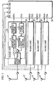
- Fig. 1 is a block diagram showing an adaptive array apparatus that is an embodiment of the present invention.
- This adaptive array apparatus includes the radio units 10, 20, 30, and 40, the antennas 17, 27, 37, and 47, and the control unit 50.
- This adaptive array apparatus is provided as a base station for mobile communication using devices such as digital portable telephones.
- the radio unit 10 includes the modulator 11, the transmission circuit 12, the switch 13, and the phase detecting unit 14.
- the modulator 11 modulates a baseband signal (symbol data) that is inputted from the control unit 50 to convert it into an intermediate frequency signal (hereinafter abbreviated to "IF signal").
- IF signal intermediate frequency signal
- the modulator 11 adds phase data and a compensation value that it receives from the control unit 50 and uses the result to generate the IF signal.
- This phase data is a phase amount that enables the generation of a same directivity pattern during transmission as during reception.
- the compensation value compensates for the phase shift in the transmission output due to the differences in characteristics between the transmission circuit 12 and the reception circuit 15.
- Examples of digital modulation methods that may be used by the modulator 11 are GMSK (Gaussian-filtered Minimum Shift Keying) and n/4 shift QPSK. (Quadrature Phase Shift Keying).
- the transmission circuit 12 converts the IF signal received from the modulator 11 into a highfrequency signal (hereinafter abbreviated to "RF signal”), and amplifies the RF signal to the transmission output level.
- RF signal a highfrequency signal
- the switch 13 switches between (1) a connection (hereinafter called the “transmission connection”) that joins the transmission circuit 12 and the phase detecting unit 14 during transmission, (2) a connection (hereinafter called the “reception connection”) that joins the phase detecting unit 14 and the reception circuit 15 during reception, and (3) a connection (hereinafter called the “loopback connection”) that joins the transmission circuit 12 and the reception circuit 15 when generating a compensation value.
- a connection hereinafter called the "transmission connection” that joins the transmission circuit 12 and the phase detecting unit 14 during transmission
- the reception connection that joins the phase detecting unit 14 and the reception circuit 15 during reception
- the loopback connection a connection that joins the transmission circuit 12 and the reception circuit 15 when generating a compensation value
- the phase detecting unit 14 operates as follows. When the modulator 11 has directly inputted an IF signal with a specific phase (this signal being the test signal), the phase detecting unit 14 detects the phase difference between the test signal directly inputted by the modulator 11 and the test signal that has been inputted via the transmission circuit 12. In this way, the phase detecting unit 14 detects a phase shift amount as the propagation characteristics of the transmission circuit 12. The phase detecting unit 14 also allows RF signals to pass as they are between the switch 13 and the antenna 17 during transmission and reception.
- the phase detecting unit 14 When detecting the phase difference, the phase detecting unit 14 converts the test signal inputted via the transmission circuit 12 into an IF signal using a frequency dividing circuit (not illustrated). The phase detecting unit 14 then compares this converted test signal with the test signal that has been directly inputted from the modulator 11 to detect the phase difference. As should be understood, the phase shift characteristics of this frequency dividing circuit are assumed to be sufficiently small as to have no effect on the formation of the directivity pattern.
- the reception circuit 15 converts the input signal into an IF signal.
- the demodulator 16 demodulates the IF signal received from the reception circuit 15 into a baseband signal.
- the radio units 20, 30, and 40 all have the same construction as the radio unit 10 and so will not be described.
- the control unit 50 performs control over transmission and reception by the radio units 10, 20, 30, and 40.
- the control unit 50 also controls the gain and phase of each radio unit so as to realize an adaptive array.
- the control unit 50 outputs a compensation value to each radio unit to compensate for the phase shift in the transmission output due to the differences in characteristics between the transmission circuit and the reception circuit in each radio unit.
- the control unit 50 also generates a compensation value for each radio unit before transmission.
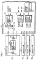
- Fig. 2 is a block diagram showing the detailed construction of the components of the control unit 50 and the modulators 11, 21, 31, and 41.
- the modulator 11 includes the adder 11a, the waveform data generating unit 11b, and the multiplier 11c.
- the adder 11a adds the phase data ⁇ 1 and the compensation value ⁇ 1c received from the control unit 50.
- the waveform data generating unit 11b generates sinewave data whose phase matches the addition result of the adder 11a.
- the multiplier 11c multiplies the sinewave data received from the waveform data generating unit 11b by the transmission data TX1 received from the control unit 50 to generate an IF signal.
- the control unit 50 includes a baseband signal generating unit 51, a selector 52, a phase data storing unit 53, a compensation value storing unit 54, and a compensation value generating unit 55.
- the control unit 50 is in fact composed of a DSP (Digital Signal Processor).
- DSP Digital Signal Processor
- the baseband signal generating unit 51 generates a baseband signal (symbol data) by converting transmission data that is serially inputted into I (in-phase) and Q (quadrature) components.
- the selector 52 outputs transmission data TX1 ⁇ TX4 produced by multiplexing the I component and Q component of the baseband signal.
- the phase data storing unit 53 stores the phase data ⁇ 1 ⁇ ⁇ 4 as phase amounts that are used by the control unit 50 when operating as an adaptive array apparatus to generate a directivity pattern during transmission that is the same as the directivity pattern during reception.
- phase data is explained in detail in Adaptive Signal Processing for Spatial Regions and Its Technical Applications (in “Transactions of the Institute of Electronics and Communication Engineers of Japan") Vol. J75-B-II No. 11 November, 1992, and so will not be described here.
- the compensation value storing unit 54 stores compensation values ⁇ 1c ⁇ ⁇ 4c as phase amounts for correcting phase shift in the transmission output due to the differences in characteristics between the transmission circuit and the reception circuit in each radio unit.
- the compensation value generating unit 55 performs a compensation value generation process that generates the compensation values ⁇ 1c ⁇ ⁇ 4c and has the resulting values stored in the compensation value storing unit 54.
- the compensation value generating unit 55 performs this compensation value generation process at predetermined intervals. This predetermined interval is preferably several days or several weeks, and should be determined in accordance with the extent to which the phase shift characteristics of the reception circuit 15 and the transmission circuit 12 change over time and the permitted difference in phase shift characteristics between these components. As one example, if the permitted range for the difference in phase shift characteristics is -10% ⁇ +10%, the predetermined interval will be set so that the compensation value will be updated before the difference in phase shift characteristics between the transmission circuit 12 and the reception circuit 15 exceeds this -10% ⁇ +10% range. This means that the compensation value generating unit 55 updates the compensation values according to changes over time in the radio units.
- Fig. 5 is a flowchart showing the details of the processing by the compensation value generating unit 55 when generating a compensation value. This compensation value generation process is explained below using Fig. 3.
- the compensation value generating unit 55 first operates for radio unit 10 (Step 51 in Fig. 5).
- the compensation value generating unit 55 sets the switch 13 in the loopback connection (Step 52), and outputs test data with a specified phase (Step 53).
- the compensation value generating unit 55 may output test data where the phase data ⁇ 1, the compensation value ⁇ 1c, and the transmission data TX1 are all zero.
- the outputted test data reaches the RX1 terminal of the control unit 50 via the route shown as (A) in Fig. 3.
- the phase of the test data will be affected by the components, especially the analog components, on this route (A). These analog components are the transmission circuit 12 and the reception circuit 15.
- the compensation value generating unit 55 compares the phase of the test data received via the RX1 terminal with the phase of the original test data, and so detects the phase shift ( ⁇ t1+ ⁇ r1) of the route (A) (Step 54).
- the compensation value generating unit 55 sets the switch 13 into the transmission connection (Step 55) and retransmits the test data (Step 56).
- This test data passes on the paths (B) and (C) in Fig. 3 and reaches the phase detecting unit 14.
- Path (C) differs from path (B) in that it also passes through the transmission circuit 12. This means that the test data on the path (C) is further affected by phase shift due to the transmission circuit 12.
- the phase detecting unit 14 compares the phase of the test data received on the path (B) with the phase of the test data received on the path (C), and so detects the phase shift ⁇ t1 due to the transmission circuit 12.
- the compensation value generating unit 55 receives this detection result via the IN1 terminal (Step 57).
- the compensation value generating unit 55 finds the difference ( ⁇ r1- ⁇ t1) in between the phase shift of a reception system and the phase shift of a transmission system in a radio unit.
- the compensation value generating unit 55 calculates the compensation values ⁇ 2c, ⁇ 3c, ⁇ 4c ( ⁇ r2- ⁇ t2, ⁇ r3- ⁇ t3, ⁇ r4- ⁇ t4) in the same way for the radio units 20, 30, and 40, and has these compensation values stored in the compensation value storing unit 54 (Steps 59, 51).
- the above processing generates a separate compensation value for each radio unit and has the resulting values stored in the compensation value storing unit 54.
- the present adaptive array apparatus performs a compensation value generation process before performing ordinary transmission or reception. As mentioned earlier, this compensation value generation process is preferably performed at regular intervals.
- the compensation value generation process generates the compensation values ⁇ 1c, ⁇ 2c, ⁇ 3c, and ⁇ 4c corresponding to the four radio units and stores the values in the compensation value storing unit 54, as shown by the representation in Fig. 3 and the flowchart in Fig. 5. ,
- the present adaptive array apparatus adjusts the gain and phase of each radio unit.
- the adaptive array apparatus adjusts gain according to conventional methods that will not be described.
- the present adaptive array apparatus performs phase adjustment by supplying each radio unit with respective phase data ⁇ 1 ⁇ ⁇ 4 for the generation of a directivity pattern, by having each radio unit add a respective compensation value ⁇ 1c ⁇ ⁇ 4c to this phase data, and by having each radio unit use the result of this addition when transmitting.
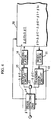
- Fig. 4 shows the operation of the radio unit 10 during transmission and reception.
- the phase shift amount ⁇ r1 of the reception circuit 15 is 0.5° while the phase shift amount ⁇ t1 of the transmission circuit 12 is 0.3°.
- the phase data ⁇ 1 in this example is 0°.
- the radio units 20, 30, and 40 all operate in the same way as the radio unit 10, so that no further explanation will be given.
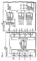
- Fig. 6 is a block diagram showing an alternative construction for the components of the control unit 50 and the modulators 11, 21, 31, and 41
- Fig. 6 shows a construction where the modulator 100 is used in place of the modulators 11, 21, 31, and 41 of Fig. 2.
- a single waveform data generating unit 101 is shared between the four radio units 10, 20, 30, and 40.
- the multiplexer 102 and the demultiplexer 103 are also provided to enable this sharing of waveform data generating unit 101.
- the waveform data generating unit 101 has a processing speed that is four times faster than each of the waveform data generating units 11b, 21b, 31b, and 41b of Fig. 2. Consequently, the multiplexer 102 multiplexes the four addition results of the four adders 11a, 21a, 31a, and 41a according to time division and outputs the multiplexed addition results to the waveform data generating unit 101.
- the demultiplexer 103 distributes each waveform generated by the waveform data generating unit 101 to an appropriate multiplier out of the multipliers 11c, 21c, 31c, and 41c.
- Quadrupling the processing speed of the modulator 100 in this way enables a reduction in the number of components and consequently a reduction in a dimensions of the circuit.
- Fig. 7 is a block diagram showing the construction of an adaptive array apparatus in a different embodiment of the present invention.
- This adaptive array apparatus only differs from the construction in Fig. 1 by including the radio units 110, 120, 130, and 140 in place of the radio units 10, 20, 30, and 40. The following explanation will focus on this difference.
- the radio unit 110 only differs from the radio unit 10 in having the phase detecting unit 14 provided between the transmission circuit 12 and the switch 13. That aside, all functions of the radio unit 110 are the same as those of the radio unit 10.
- the radio units 120, 130, and 140 are the same as the radio unit 110, and so will not be explained.
- phase detecting unit 14 facilitates the installation of the phase detecting unit 14.
- the phase detecting unit 14 may instead be provided between the switch 13 and the reception circuit 15.
- the compensation value generation process in this embodiment should preferably be performed regularly, with the interval between executions being determined according to the extent to which the characteristics of the circuit elements change over time.
- a compensation value for each radio unit may be written into the compensation value storing unit 54 at the factory before shipment.
- the adaptive array apparatus of the preferred embodiment corrects phase during transmission according to a difference in phase shift between the transmission circuit and the reception circuit. Even when there is a large difference in characteristics between the transmission circuit and the reception circuit, the directivity pattern for transmission can be made the same as the directivity pattern for reception. This is especially effective when low-cost components are used in the transmission circuit and reception circuit of a base station used in mobile communication, since such the difference in characteristics between such components would otherwise be problematic.
Landscapes
- Engineering & Computer Science (AREA)
- Computer Networks & Wireless Communication (AREA)
- Signal Processing (AREA)
- Radio Transmission System (AREA)
- Variable-Direction Aerials And Aerial Arrays (AREA)
- Cable Transmission Systems, Equalization Of Radio And Reduction Of Echo (AREA)
Claims (8)
- Dispositif à groupement adaptatif qui comprend une pluralité d'unités radio (10, 20, 30, 40) qui chacune ont une unité d'émission (12), une unité de réception (15), et une antenne (17), pour générer un diagramme de directivité pendant l'émission qui est sensiblement le même que le diagramme de directivité généré pendant la réception, le dispositif à groupement adaptatif comprenant :un moyen de génération (50, 55) pour générer des signaux de test ;un premier moyen de détection (14) pour chaque unité radio (10, 20, 30, 40), pour détecter, l'orsqu'un signal test passe l'unité d'émission (12) dans chaque unité radio (10, 20, 30, 40), une première valeur de déphasage (Δφt1) pour chaque unité radio (10, 20, 30, 40) ;un second moyen de détection (50, 55) pour chaque unité radio, pour détecter, lorsque le signal de test passe l'unité d'émission (12) et l'unité de réception (15) dans l'ordre dans l'unité radio (10, 20, 30, 40), une seconde valeur de déphasage (Δφt1+Δφr1) pour chaque unité radio (10, 20, 30, 40) ;un moyen de calcul (50, 55) pour calculer une différence de déphasage entre l'unité de réception (15) et l'unité d'émission (12) dans chaque unité radio (10, 20, 30, 40) en utilisant la première valeur de déphasage (Δφt1) et la seconde valeur de déphasage (Δφt1+Δφr1) de chaque unité radio (10, 20, 30,40) ; etun moyen de compensation (50, 55), pour compenser, pour chaque unité radio (10, 20, 30, 40), une grandeur de phase utilisée lors de la génération d'un diagramme de directivité pour un signal de sortie en ajoutant la différence de déphasage calculée à la grandeur de phase.
- Dispositif à groupement adaptatif selon la revendication 1, comprenant un moyen de stockage (54) pour stocker la différence de déphasage calculée par le moyen de calcul.
- Dispositif à groupement adaptatif selon la revendication 1 ou 2,
dans lequel le moyen de calcul calcule la différence de déphasage en réalisant une soustraction en utilisant la seconde valeur de déphasage (Δφt1)+Δφr1) et une valeur qui est le double de la première valeur de déphasage (2Δφt1). - Dispositif à groupement adaptatif selon la revendication 1, 2 ou 3,
dans lequel le moyen de calcul (50, 55) calcule la différence de déphasage à un intervalle prédéterminé. - Dispositif à groupement adaptatif selon la revendication 4,
dans lequel l'intervalle prédéterminé utilisé par le moyen de calcul (50, 55) est une période qui est déterminée selon :(1) un degré auquel une différence en grandeurs de déphasage entre l'unité d'émission et l'unité de réception de chaque unité radio (10, 20, 30, 40) change au cours du temps, et(2) une plage permise pour la différence en grandeurs de déphasage. - Procédé de compensation destiné à être utilisé dans un dispositif à groupement adaptatif qui comprend une pluralité d'unités radio (10, 20, 30, 40) qui ont chacune une unité d'émission (12), une unité de réception (15) et une antenne (17), et génèrent un diagramme de directivité pendant l'émission qui est sensiblement le même que le diagramme de directivité généré pendant la réception, le procédé de compensation compensant une grandeur de phase qui est utilisée lors de la génération d'un diagramme de directivité,
le procédé de compensation comprenant :la génération de signaux de test de sortie ;premièrement, la détection, pour chaque unité radio (10, 20, 30, 40), lorsqu'un signal de test passe l'unité d'émission (12) dans chaque unité radio (10, 20, 30, 40), une première valeur de déphasage (Δφt1) pour chaque unité radio (10, 20, 30, 40) ;deuxièmement, la détection, lorsque le signal de test passe l'unité d'émission (12), et l'unité de réception (15) dans l'ordre dans chaque unité radio (10, 20, 30, 40), une seconde valeur de déphasage pour chaque unité radio (10, 20, 30, 40) ;calcul d'une différence de déphasage entre l'unité de réception (15) et l'unité d'émission (12) dans chaque unité radio (10, 20, 30, 40) en utilisant la première valeur de déphasage (Δφt1) et la seconde valeur de déphasage (Δφt1+Δφr1) de chaque unité radio (10, 20, 30, 40) ; etcompensation, pour chaque unité radio (10, 20, 30, 40), d'une grandeur de phase utilisée lors de la génération d'un diagramme de directivité destiné à être utilisé pour un signal de sortie en ajoutant la différence de déphasage calculée à la grandeur de phase. - Procédé de compensation selon la revendication 6,
dans lequel l'étape de calcul calcule la différence de déphasage en réalisant une soustraction en utilisant la seconde valeur de déphasage (Δφt1+Δφr1) et une valeur qui est le double de la première valeur de déphasage (2Δφt1). - Procédé de compensation selon la revendication 6,
dans lequel l'étape de calcul calcule la différence de déphasage à un intervalle prédéterminé.
Applications Claiming Priority (2)
| Application Number | Priority Date | Filing Date | Title |
|---|---|---|---|
| JP15937797A JP3389455B2 (ja) | 1997-06-17 | 1997-06-17 | アダプティブアレイ装置およびその補正方法 |
| PCT/JP1998/005652 WO2000036701A1 (fr) | 1997-06-17 | 1998-12-15 | Dispositif adaptatif de correction de phase pour produire une configuration directionnelle et procede de correction |
Publications (3)
| Publication Number | Publication Date |
|---|---|
| EP1143559A1 EP1143559A1 (fr) | 2001-10-10 |
| EP1143559A4 EP1143559A4 (fr) | 2003-01-29 |
| EP1143559B1 true EP1143559B1 (fr) | 2006-03-01 |
Family
ID=14209605
Family Applications (1)
| Application Number | Title | Priority Date | Filing Date |
|---|---|---|---|
| EP98959206A Expired - Lifetime EP1143559B1 (fr) | 1997-06-17 | 1998-12-15 | Dispositif adaptatif de correction de phase pour produire une configuration directionnelle et procede de correction |
Country Status (8)
| Country | Link |
|---|---|
| US (1) | US7110794B1 (fr) |
| EP (1) | EP1143559B1 (fr) |
| JP (1) | JP3389455B2 (fr) |
| CN (1) | CN1181597C (fr) |
| AU (1) | AU781463B2 (fr) |
| DE (1) | DE69833685T2 (fr) |
| HK (1) | HK1040834B (fr) |
| WO (1) | WO2000036701A1 (fr) |
Families Citing this family (14)
| Publication number | Priority date | Publication date | Assignee | Title |
|---|---|---|---|---|
| HK1047001B (zh) | 1999-03-30 | 2005-06-03 | 三洋电机株式会社 | 无线装置及其天线方向性的校准方法 |
| JP4318389B2 (ja) | 2000-04-03 | 2009-08-19 | 三洋電機株式会社 | アダプティブアレー装置、無線基地局、携帯電話機 |
| JP3877678B2 (ja) * | 2000-07-14 | 2007-02-07 | 三洋電機株式会社 | キャリブレーション装置、アダプティブアレー装置、キャリブレーション方法、プログラム記録媒体及びプログラム |
| JP2002353865A (ja) * | 2001-05-23 | 2002-12-06 | Nec Corp | アレーアンテナ送受信装置及びそのキャリブレーション方法 |
| JP2003078462A (ja) * | 2001-08-31 | 2003-03-14 | Sanyo Electric Co Ltd | 無線装置、その信号受信方法、そのフィルタ係数測定方法、およびそのフィルタ係数測定プログラム |
| ITBO20020012A1 (it) * | 2002-01-11 | 2003-07-11 | Consiglio Nazionale Ricerche | Apparecchiatura per il rilevamento di radiazioni elettromagnetiche , in particolare per applicazioni radioastronomiche |
| TWI326047B (en) * | 2006-11-29 | 2010-06-11 | Ind Tech Res Inst | Method and apparatus for reading radio frequency identification tags |
| US8897717B2 (en) | 2010-07-28 | 2014-11-25 | Honeywell International Inc. | Dual-feed antenna array with integral comparison circuit for phase and amplitude calibration |
| CN103477570B (zh) * | 2011-08-02 | 2016-04-27 | 松下电器产业株式会社 | 相控阵发送装置 |
| CN102610920B (zh) * | 2012-03-22 | 2014-12-24 | 中国联合网络通信集团有限公司 | 天馈系统和相位校准方法 |
| EP3557786A1 (fr) * | 2018-04-16 | 2019-10-23 | Samsung Electronics Co., Ltd. | Procédé de test de circuit intégré rf |
| CN108763740B (zh) * | 2018-05-28 | 2019-12-27 | 西北工业大学 | 一种基于双振速传感器声探头灵活指向性图的设计方法 |
| JP7161822B2 (ja) * | 2019-06-07 | 2022-10-27 | 旭化成エレクトロニクス株式会社 | 位相調整回路及び位相調整方法 |
| JP7753854B2 (ja) * | 2021-12-14 | 2025-10-15 | 日本電気株式会社 | アクティブ・アンテナ・システム及びその方法 |
Family Cites Families (11)
| Publication number | Priority date | Publication date | Assignee | Title |
|---|---|---|---|---|
| JPS6059853B2 (ja) * | 1981-02-27 | 1985-12-27 | 住友重機械工業株式会社 | 射出吹込成形方法 |
| JPS5945582A (ja) | 1982-09-06 | 1984-03-14 | Kubota Ltd | ラベル発行機におけるコ−ド設定方式 |
| JPS5945582U (ja) * | 1982-09-18 | 1984-03-26 | 三菱電機株式会社 | アクテイブフエ−ズドアレイレ−ダ |
| JPS61117902A (ja) | 1984-11-13 | 1986-06-05 | Mitsubishi Electric Corp | フエイズドアレイアンテナ用送受信モジユ−ル |
| JPH01154604A (ja) * | 1987-12-10 | 1989-06-16 | Nec Corp | アレイアンテナ |
| US5546090A (en) * | 1991-12-12 | 1996-08-13 | Arraycomm, Inc. | Method and apparatus for calibrating antenna arrays |
| JPH06216625A (ja) | 1993-01-13 | 1994-08-05 | Mitsubishi Electric Corp | 電子走査アンテナ装置 |
| JP3305938B2 (ja) * | 1995-11-16 | 2002-07-24 | 株式会社東芝 | フェーズドアレイアンテナ装置 |
| JP3816162B2 (ja) | 1996-10-18 | 2006-08-30 | 株式会社東芝 | アダプティブアンテナにおけるビーム幅制御方法 |
| KR100312836B1 (ko) * | 1997-06-03 | 2001-12-28 | 다치카와 게이지 | 어댑티브어레이송수신기 |
| JP3585701B2 (ja) * | 1997-06-12 | 2004-11-04 | 富士通株式会社 | セルラ移動通信システム無線基地局 |
-
1997
- 1997-06-17 JP JP15937797A patent/JP3389455B2/ja not_active Expired - Fee Related
-
1998
- 1998-12-15 US US09/856,499 patent/US7110794B1/en not_active Expired - Fee Related
- 1998-12-15 WO PCT/JP1998/005652 patent/WO2000036701A1/fr not_active Ceased
- 1998-12-15 CN CNB988143976A patent/CN1181597C/zh not_active Expired - Fee Related
- 1998-12-15 DE DE69833685T patent/DE69833685T2/de not_active Expired - Fee Related
- 1998-12-15 AU AU15075/99A patent/AU781463B2/en not_active Ceased
- 1998-12-15 EP EP98959206A patent/EP1143559B1/fr not_active Expired - Lifetime
- 1998-12-15 HK HK02102250.9A patent/HK1040834B/en not_active IP Right Cessation
Also Published As
| Publication number | Publication date |
|---|---|
| CN1337076A (zh) | 2002-02-20 |
| JP3389455B2 (ja) | 2003-03-24 |
| HK1040834A1 (en) | 2002-06-21 |
| EP1143559A1 (fr) | 2001-10-10 |
| CN1181597C (zh) | 2004-12-22 |
| US7110794B1 (en) | 2006-09-19 |
| AU781463B2 (en) | 2005-05-26 |
| EP1143559A4 (fr) | 2003-01-29 |
| WO2000036701A1 (fr) | 2000-06-22 |
| AU1507599A (en) | 2000-07-03 |
| DE69833685D1 (de) | 2006-04-27 |
| HK1040834B (en) | 2006-08-25 |
| JPH118507A (ja) | 1999-01-12 |
| DE69833685T2 (de) | 2006-11-16 |
Similar Documents
| Publication | Publication Date | Title |
|---|---|---|
| CN101651480B (zh) | 有源天线、基站、刷新幅度和相位的方法及信号处理方法 | |
| KR100656979B1 (ko) | 스마트 안테나 어레이 시스템의 실시간 교정 방법 | |
| EP1143559B1 (fr) | Dispositif adaptatif de correction de phase pour produire une configuration directionnelle et procede de correction | |
| US7058418B2 (en) | Adaptive array device, wireless base station and cellular telephone | |
| EP1670094B1 (fr) | Procédé de calibration d'un système d'antenne intelligente | |
| JP3519276B2 (ja) | キャリブレーション装置 | |
| CN100576784C (zh) | 发射设备 | |
| EP1329983A2 (fr) | Dispositif et procédé d'étalonnage pour un système d'antennes | |
| CA2227522C (fr) | Appareil d'auto-etalonnage et procede afferent pour unite de communication | |
| CN102405555B (zh) | 多天线波束成型系统中接收链路的校准方法、装置及系统 | |
| US5710977A (en) | Apparatus for measuring multipath propagation characteristics | |
| JP4447380B2 (ja) | アレーアンテナ受信装置及び送信装置 | |
| EP1093186B1 (fr) | Radioemetteur et procede de reglage de la directivite d'emission | |
| JP2001102996A (ja) | 基地局装置及び無線通信方法 | |
| JP2001053663A (ja) | 多元接続通信装置 | |
| JP4614814B2 (ja) | 送信装置 | |
| JP3813537B2 (ja) | Cdma移動通信基地局装置 | |
| JP2003124731A (ja) | アダプティブアレーアンテナ及びそのキャリブレーション方法 | |
| WO1999007034A1 (fr) | Technique de calibrage d'antenne et dispositif correspondant | |
| JP2017050823A (ja) | 無線通信システム | |
| JP2006295793A (ja) | 無線通信装置及び方法 | |
| HK1070220A1 (en) | Array antenna communication device | |
| HK1070220B (en) | Array antenna communication device |
Legal Events
| Date | Code | Title | Description |
|---|---|---|---|
| PUAI | Public reference made under article 153(3) epc to a published international application that has entered the european phase |
Free format text: ORIGINAL CODE: 0009012 |
|
| 17P | Request for examination filed |
Effective date: 20010710 |
|
| AK | Designated contracting states |
Kind code of ref document: A1 Designated state(s): DE FR GB |
|
| A4 | Supplementary search report drawn up and despatched |
Effective date: 20021212 |
|
| 17Q | First examination report despatched |
Effective date: 20031017 |
|
| GRAP | Despatch of communication of intention to grant a patent |
Free format text: ORIGINAL CODE: EPIDOSNIGR1 |
|
| GRAS | Grant fee paid |
Free format text: ORIGINAL CODE: EPIDOSNIGR3 |
|
| GRAA | (expected) grant |
Free format text: ORIGINAL CODE: 0009210 |
|
| AK | Designated contracting states |
Kind code of ref document: B1 Designated state(s): DE FR GB |
|
| REG | Reference to a national code |
Ref country code: GB Ref legal event code: FG4D |
|
| REF | Corresponds to: |
Ref document number: 69833685 Country of ref document: DE Date of ref document: 20060427 Kind code of ref document: P |
|
| REG | Reference to a national code |
Ref country code: HK Ref legal event code: GR Ref document number: 1040834 Country of ref document: HK |
|
| ET | Fr: translation filed | ||
| PLBE | No opposition filed within time limit |
Free format text: ORIGINAL CODE: 0009261 |
|
| STAA | Information on the status of an ep patent application or granted ep patent |
Free format text: STATUS: NO OPPOSITION FILED WITHIN TIME LIMIT |
|
| 26N | No opposition filed |
Effective date: 20061204 |
|
| PGFP | Annual fee paid to national office [announced via postgrant information from national office to epo] |
Ref country code: FR Payment date: 20081212 Year of fee payment: 11 |
|
| PGFP | Annual fee paid to national office [announced via postgrant information from national office to epo] |
Ref country code: DE Payment date: 20081211 Year of fee payment: 11 |
|
| PGFP | Annual fee paid to national office [announced via postgrant information from national office to epo] |
Ref country code: GB Payment date: 20081210 Year of fee payment: 11 |
|
| REG | Reference to a national code |
Ref country code: FR Ref legal event code: TP |
|
| GBPC | Gb: european patent ceased through non-payment of renewal fee |
Effective date: 20091215 |
|
| REG | Reference to a national code |
Ref country code: FR Ref legal event code: ST Effective date: 20100831 |
|
| PG25 | Lapsed in a contracting state [announced via postgrant information from national office to epo] |
Ref country code: FR Free format text: LAPSE BECAUSE OF NON-PAYMENT OF DUE FEES Effective date: 20091231 |
|
| PG25 | Lapsed in a contracting state [announced via postgrant information from national office to epo] |
Ref country code: DE Free format text: LAPSE BECAUSE OF NON-PAYMENT OF DUE FEES Effective date: 20100701 |
|
| PG25 | Lapsed in a contracting state [announced via postgrant information from national office to epo] |
Ref country code: GB Free format text: LAPSE BECAUSE OF NON-PAYMENT OF DUE FEES Effective date: 20091215 |