EP1146488A2 - Münzausgabevorrichtung und Ausgabemechanismus - Google Patents
Münzausgabevorrichtung und Ausgabemechanismus Download PDFInfo
- Publication number
- EP1146488A2 EP1146488A2 EP01303405A EP01303405A EP1146488A2 EP 1146488 A2 EP1146488 A2 EP 1146488A2 EP 01303405 A EP01303405 A EP 01303405A EP 01303405 A EP01303405 A EP 01303405A EP 1146488 A2 EP1146488 A2 EP 1146488A2
- Authority
- EP
- European Patent Office
- Prior art keywords
- coin
- dispensing
- stack
- coins
- drive mechanism
- Prior art date
- Legal status (The legal status is an assumption and is not a legal conclusion. Google has not performed a legal analysis and makes no representation as to the accuracy of the status listed.)
- Withdrawn
Links
Images



Classifications
-
- G—PHYSICS
- G07—CHECKING-DEVICES
- G07D—HANDLING OF COINS OR VALUABLE PAPERS, e.g. TESTING, SORTING BY DENOMINATIONS, COUNTING, DISPENSING, CHANGING OR DEPOSITING
- G07D1/00—Coin dispensers
Definitions
- the present invention relates to a coin dispensing mechanism, particularly but not exclusively for dispensing coins laterally from an end of a stack.
- the present invention further relates to a coin dispenser having a plurality of such tubes and coin dispensing mechanisms.
- EP-A-903702. This dispenser has an electric motor, planetary gear mechanism and dispensing disc, with holes for receiving coins arranged around its circumference, all coaxially arranged. Although this device aims to reduce the horizontal extent of the dispensing mechanism, the dispensing disc imposes a horizontal spacing between the coins and the motor and gear mechanism.
- a coin dispensing mechanism for dispensing coins laterally from a tube, comprising a dispensing member for engaging a coin and dispensing it from the tube, a motor and a drive mechanism for connecting the motor to the dispensing member, the motor and drive mechanism being substantially bounded by the projection of the outer walls of the tube along the axis of the tube.
- the motor is aligned substantially coaxially with the tube.
- An advantage of this arrangement is that the relative positions of the tubes within a housing or bounded area can be selected freely, subject only to allowing room for coins to be dispensed from the tube. Another advantage is that the tubes can be positioned close together without their drive mechanisms and/or motors impinging on each other.
- a coin dispenser comprising a plurality of coin storage tubes, and a respective plurality of motors each associated with a respective one of the tubes so as to dispense coins only from the associated tube.
- a coin dispenser having a dispensing aperture, and a plurality of coin storage tubes arranged such that the intersections of their axes with a horizontal plane lie on an arc, the tubes having lateral dispensing slots arranged approximately equidistantly from the edge of the dispensing aperture. This arrangement may provide efficient packing of the tubes around the dispensing aperture.
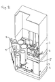
- a coin dispenser has a base 2 carrying a plurality of coin storage tubes 4a to 4e arranged around the edge of a dispensing aperture 5. Only two of the storage tubes 4 are shown in place in this Figure. At the bottom of each of the storage tubes 4a to 4e is a coin dispensing slot 6a to 6e from which coins can be dispensed laterally. The coin dispensing slots 6 all face towards the dispensing aperture 5 so that coins 8 passing out of one of the coin dispensing slots 6 fall through the dispensing aperture 5 under the force of gravity.
- the tubes 4 are arranged in an arc on three sides of the dispensing aperture.
- the coin dispenser includes a housing 3 which is attached to the base 2 and surrounds the coin tubes 4.
- One side of the housing 3 is open to allow the coin tubes 4, mounted on a cassette 7, to be loaded and removed.
- the top of the housing 3 is also open.
- the cassette 7 has a vertical passage 9 of similar horizontal cross-section to the dispensing aperture 5. This arrangement allows multiple coin dispensers to be stacked, as shown for example in Figure 2, to give a coin dispenser of greater capacity, with coins dispensed by an upper coin dispenser falling through the vertical passage of a lower coin dispenser and passing through the dispensing aperture 5 thereof.
- the coins are dispensed one-by-one from the bottom of the coin storage tubes 4 by respective dispensing mechanisms 10a to 10e controlled by electronic control circuitry (not shown).
- Each dispensing mechanism 10 is located directly under its associated tube 4 and projects very little outwards from under the tube 4 in its rest position. In its dispensing position, the dispensing mechanism 10 projects outwards in the dispensing direction so as to support the dispensed coin.
- One or more additional dispensing mechanisms 10 and associated tubes 4 may be provided as an add-on component separate from the cassette 7 and base 2.
- This add-on component may be attached to a side of the housing 3 other than the open side into which the cassette 7 is inserted.
- the add-on component is preferably controlled by the electronic control circuitry in concert with the dispensing mechanisms 10a to 10e integrated with the base 2.
- a separate dispensing path may be provided for coins dispensed by the add-on component into the dispensing area, or the dispensing area may extend directly below the add-on component so that the coins drop down into it directly.
- the dispensing mechanism 10 is shown in more detail in Figures 3 and 4.
- a gear casing 12 which may form part of or be removably attached to the base 2, is located above a compact cylindrical electric motor 14, for example Mabuchi MotorTM part no. RF - 300PA - 11400.
- This motor has a speed at maximum efficiency of 2400 RPM and therefore needs a high reduction ratio to provide a suitable speed and power for dispensing a coin.
- a dual planetary gear train provides this reduction without extending outside the axial projection of the tube 4.
- a first sun gear 15 drives three equally angularly spaced first planet gears 16a to 16c.
- the first planet gears 16 engage a first gear cage 17.
- the first gear cage 17 is fixed with respect to the casing 12, and has an upwardly extending circumferential lip 19.
- the first planet gears 16a to 16c are axially fixed to respective second planet gears 22a to 22c.
- the first and second planet gears are axially rotatably attached to an equilateral triangular plate 18, which maintains the equiangular spacing of the planet gears.
- the second planet gears 22 engage a second gear cage 24 which is rotatable with respect to the casing 12 and the first gear cage 17, and has an outer circumferential groove 20 into which the lip 19 is located, allowing the second gear cage 24 to rotate coaxially with the first gear cage 17.
- the upper surface of the second gear cage 24 carries an upwardly-projecting drive pin 28 which engages a dispensing link arm 30.
- the dual planetary gear train reduces the rotational speed of the motor of 2400 RPM to a rotational speed of the drive pin 28 of approximately 120 RPM or greater to allow coins to be dispensed from a single tube at a rate of at least one per second.
- the dispensing link arm 30 is pivoted about a pin 32 which is formed as a projection of the casing 12 or base 2, and may be located adjacent a side of the storage tube 4.
- a slot 33 within which the drive pin 28 slides so that the dispensing link arm 30 reciprocates in the dispensing direction when the second gear cage 24 rotates.
- an upper layer having a support section 34, on which the bottom coin in the tube 4 rests, and a pusher pin 36 which is housed in its rest position in a recess in the side wall of the tube 4 so that it does not project into the internal volume of the tube.
- the pusher pin 36 abuts the edge of the bottom coin to be dispensed and pushes it towards the dispensing slot 6 so as to dispense the coin through the dispensing aperture 4.
- the base 2 as shown in Figure 1 has apertures 3a to 3e which allow the drive pin 28 of each dispensing mechanism 10 to rotate through a limited arc in which the mechanical advantage of the drive mechanism is high.
- a sensor (not shown) detects when the drive pin 28 reaches either end of the arc and abuts the base 2.
- the sensor may comprise a microswitch at either end of the arc, or may be connected to the current supply circuit of the motor 14 so as to detect the increased load on the motor caused by the drive pin 28 abutting the base 2.
- a controller (not shown) reverses the voltage applied to the motor 14 to retract the dispensing link arm 30.
- the voltage is reversed only when the next coin is to be dispensed.
- the aperture 3 allow complete rotation of the drive pin 28 and a rotational position sensor detects whether the dispensing mechanism 10 has reached the fully extended or fully retracted position, the controller then determining whether to reverse or disconnect the voltage supplied to the motor 14.
- the dual planetary gear mechanism described above is just one example of a compact reducing gear mechanism which extends as little as possible away from the axis of the motor.
- Alternative planetary and other gear arrangements can be used in other embodiments of the present invention.
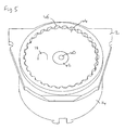
- Figure 5 shows an alternative gear mechanism for driving the dispensing link arm 30, in which a planocentric gear is used to provide a single stage gearing reduction.
- the axle 40 of the motor 14 is fixed off-centre to a circular eccentric member 42 which is rotatably mounted concentrically within a planocentric gear 44 having 29 teeth.
- the planocentric gear 44 rotates around a gear cage 46 which has 30 teeth and is fixed relative to the base 2, driven by the eccentric member 42, to give a reduction factor of 30 in the rotation of the drive pin 28 around the axle 40.
- the term 'coin' as used herein includes tokens and the like, and includes polygonal, non-circular coins such as the UK 50 and 20 pence pieces.
- the storage tubes for these coins may be correspondingly polygonal cylinders.
- the term 'cylindrical' does not imply that the tubes are circular cylinders.
- the axes of the tubes could be at an angle to the plane of the dispensing end of the tube, so that the term 'cylindrical' does not imply a right cylinder.
- the coin storage tubes may be filled from coins deposited in a coin acceptance mechanism, or may be pre-loaded by the operator.
- the coin storage tubes need not dispense from the bottom, with the stack moving up to the dispensing end under the force of gravity; instead, the stack could be urged towards a dispensing end at the top of the stack, for example by a spring at the bottom of each tube.
- 'motor' refers broadly to any type of device which converts another form of energy into mechanical kinetic energy, including without limitation a pulsing or rotary solenoid.
Landscapes
- Physics & Mathematics (AREA)
- General Physics & Mathematics (AREA)
- Control Of Vending Devices And Auxiliary Devices For Vending Devices (AREA)
- De-Stacking Of Articles (AREA)
Applications Claiming Priority (2)
| Application Number | Priority Date | Filing Date | Title |
|---|---|---|---|
| GB0009075A GB2361344A (en) | 2000-04-12 | 2000-04-12 | Coin dispenser and dispensing mechanism |
| GB0009075 | 2000-04-12 |
Publications (2)
| Publication Number | Publication Date |
|---|---|
| EP1146488A2 true EP1146488A2 (de) | 2001-10-17 |
| EP1146488A3 EP1146488A3 (de) | 2004-01-21 |
Family
ID=9889812
Family Applications (1)
| Application Number | Title | Priority Date | Filing Date |
|---|---|---|---|
| EP01303405A Withdrawn EP1146488A3 (de) | 2000-04-12 | 2001-04-11 | Münzausgabevorrichtung und Ausgabemechanismus |
Country Status (3)
| Country | Link |
|---|---|
| US (1) | US6564965B2 (de) |
| EP (1) | EP1146488A3 (de) |
| GB (1) | GB2361344A (de) |
Cited By (1)
| Publication number | Priority date | Publication date | Assignee | Title |
|---|---|---|---|---|
| CN110136318A (zh) * | 2019-05-15 | 2019-08-16 | 武汉科技大学 | 一种硬币包装机 |
Families Citing this family (9)
| Publication number | Priority date | Publication date | Assignee | Title |
|---|---|---|---|---|
| US20050070399A1 (en) * | 2003-09-26 | 2005-03-31 | Molon Motor & Coil Corp. | Planetary gear motor assembly and method of manufacture |
| EP2079059B1 (de) * | 2005-01-12 | 2011-12-28 | Japan Cash Machine Co., Ltd. | Vorrichtung zur Validierung wertvoller Papiere |
| CA2609919C (en) * | 2005-06-02 | 2014-02-18 | Coin Acceptors, Inc. | System and method for payout of coins from multiple coin storage units |
| US20070125621A1 (en) * | 2005-12-06 | 2007-06-07 | Locknet, Llc | Token Operated Access Control System |
| US8827777B2 (en) * | 2007-05-24 | 2014-09-09 | National Rejectors, Inc. Gmbh | Method for operating a coin dispensing device and a coin dispensing device |
| DE102007046391B4 (de) * | 2007-09-20 | 2011-02-03 | National Rejectors, Inc. Gmbh | Vorrichtung zum Sortieren von Münzen |
| JP6402332B2 (ja) * | 2015-09-09 | 2018-10-10 | 旭精工株式会社 | コインホッパー |
| WO2018039265A1 (en) * | 2016-08-22 | 2018-03-01 | Crane Payment Innovations, Inc. | Money item canister |
| EP3695390A4 (de) * | 2017-10-10 | 2021-07-14 | Crane Payment Innovations, Inc. | Münzausgabevorrichtung |
Citations (2)
| Publication number | Priority date | Publication date | Assignee | Title |
|---|---|---|---|---|
| US5595535A (en) | 1994-06-28 | 1997-01-21 | National Rejectors, Inc. | Device for paying off coins from at least a pair of coin collecting tubes |
| EP0903702A2 (de) | 1997-09-12 | 1999-03-24 | Asahi Seiko Kabushiki Kaisha | Ausgabevorrichtung für Scheiben |
Family Cites Families (28)
| Publication number | Priority date | Publication date | Assignee | Title |
|---|---|---|---|---|
| US626528A (en) * | 1899-06-06 | debremond | ||
| US792923A (en) * | 1903-12-18 | 1905-06-20 | William N Porter | Money-changing apparatus. |
| US1036645A (en) * | 1911-11-01 | 1912-08-27 | Elihu N Kleinbaum | Change-making apparatus. |
| US1454303A (en) * | 1921-03-05 | 1923-05-08 | White Nelson | Money-paying device |
| US2149444A (en) * | 1935-10-25 | 1939-03-07 | Kohlmann Gerhard | Automatic coin counting and wrapping machine |
| US2610721A (en) * | 1946-11-04 | 1952-09-16 | Leonard L Pruyn | Automatic electric selective silver coin changer |
| US2782791A (en) * | 1952-09-15 | 1957-02-26 | Serv Kraft Inc | Coin dispensing mechanism |
| GB1415162A (en) * | 1971-12-18 | 1975-11-26 | Shaw A | Coin supply monitor |
| US3783885A (en) * | 1972-06-27 | 1974-01-08 | P Griffiths | Disc dispensing apparatus |
| US4010766A (en) * | 1975-12-08 | 1977-03-08 | Ncr Corporation | Change dispensing apparatus |
| AU505313B1 (en) * | 1978-10-24 | 1979-11-15 | Ainsworth, L.H. | Automatic coin dispenser |
| DE3318124A1 (de) * | 1983-05-18 | 1984-11-22 | Heinrich H. Klüssendorf GmbH & Co KG, 1000 Berlin | Vorrichtung zum speichern flacher und vorzugsweise runder gegenstaende |
| JPS6044160U (ja) * | 1983-09-01 | 1985-03-28 | 株式会社 日本コインコ | 硬貨選別制御器におけるつり銭払出装置 |
| DE3573959D1 (en) * | 1984-08-29 | 1989-11-30 | Autelca Ag | Coin storage and vending machine |
| FR2609341B1 (fr) * | 1987-01-06 | 1989-03-03 | Cga Hbs | Distributeur automatique a rendu de monnaie |
| GB2203137B (en) * | 1987-02-25 | 1990-09-26 | Mars Inc | Coin dispensers |
| KR0122599B1 (ko) * | 1988-06-22 | 1997-12-05 | 오까다 마사하루 | 경화수납 및 배출장치 |
| US4997405A (en) * | 1989-04-26 | 1991-03-05 | Ardac, Inc. | Coin payout system |
| DE4041078A1 (de) * | 1990-12-21 | 1992-06-25 | Mega Spielgeraete Entwicklungs | Vorrichtung zur ermittlung des fuellstandes einer muenzstapelroehre in einem muenzbetaetigten automaten |
| DE4233760A1 (de) * | 1991-10-09 | 1993-04-15 | Georg Pruemm | Restgeldgeber |
| DE9209201U1 (de) * | 1992-04-01 | 1992-09-10 | Jäger, Jürgen, 3504 Kaufungen | Münzausgeber für Unterhaltungs- und Warenautomaten |
| GB2274190B (en) * | 1993-01-12 | 1996-05-08 | Mars Inc | Coin dispensing apparatus |
| JPH0844920A (ja) * | 1994-07-29 | 1996-02-16 | Nippon Conlux Co Ltd | コイン払出装置 |
| JP3223725B2 (ja) * | 1994-10-17 | 2001-10-29 | 富士電機株式会社 | 硬貨払出し装置 |
| JPH08123987A (ja) * | 1994-10-28 | 1996-05-17 | Tec Corp | 硬貨収納払出し装置 |
| JPH08315206A (ja) * | 1995-05-19 | 1996-11-29 | Sanden Corp | 釣銭払い出し装置 |
| WO1998058355A2 (en) * | 1997-06-18 | 1998-12-23 | Mars, Incorporated | Currency handling apparatus |
| DE19738019C2 (de) * | 1997-08-30 | 1999-12-23 | Nat Rejectors Gmbh | Vorrichtung zum Auszahlen von Münzen aus Münzstapeltuben |
-
2000
- 2000-04-12 GB GB0009075A patent/GB2361344A/en not_active Withdrawn
-
2001
- 2001-04-11 EP EP01303405A patent/EP1146488A3/de not_active Withdrawn
- 2001-04-11 US US09/832,495 patent/US6564965B2/en not_active Expired - Lifetime
Patent Citations (2)
| Publication number | Priority date | Publication date | Assignee | Title |
|---|---|---|---|---|
| US5595535A (en) | 1994-06-28 | 1997-01-21 | National Rejectors, Inc. | Device for paying off coins from at least a pair of coin collecting tubes |
| EP0903702A2 (de) | 1997-09-12 | 1999-03-24 | Asahi Seiko Kabushiki Kaisha | Ausgabevorrichtung für Scheiben |
Cited By (1)
| Publication number | Priority date | Publication date | Assignee | Title |
|---|---|---|---|---|
| CN110136318A (zh) * | 2019-05-15 | 2019-08-16 | 武汉科技大学 | 一种硬币包装机 |
Also Published As
| Publication number | Publication date |
|---|---|
| US20010055946A1 (en) | 2001-12-27 |
| GB0009075D0 (en) | 2000-05-31 |
| EP1146488A3 (de) | 2004-01-21 |
| US6564965B2 (en) | 2003-05-20 |
| GB2361344A (en) | 2001-10-17 |
Similar Documents
| Publication | Publication Date | Title |
|---|---|---|
| US6564965B2 (en) | Coin dispenser and dispensing mechanism | |
| CA2684313A1 (en) | Vending apparatus | |
| WO1995030213A1 (en) | A device for releasing the products in a vending machine | |
| US7244177B2 (en) | Variable volume storage member for a coin dispensing apparatus | |
| WO2014201871A1 (zh) | 一种整卷硬币出币装置 | |
| ES2226527B1 (es) | Dispositivo de guiado de discos. | |
| CN110264620A (zh) | 一种胶囊饮品料包出货器 | |
| US20120156977A1 (en) | Coin hopper with an upward coin passage | |
| JP4002962B2 (ja) | サイズ変更可能なコインホッパ装置 | |
| JP6638893B2 (ja) | メダル積上げ装置 | |
| JP2722396B2 (ja) | 景品払出し機 | |
| JP3854740B2 (ja) | 硬貨払出装置 | |
| EP4148695B1 (de) | Münzfördervorrichtung und münztrichter | |
| CN1902665A (zh) | 自动售货机 | |
| JP4161233B2 (ja) | 紙幣処理装置 | |
| JP3650069B2 (ja) | コイン送り出し装置 | |
| JP4461851B2 (ja) | コイン回転送出し機構、コイン払出し装置およびスロット遊技機 | |
| JP4507689B2 (ja) | コイン排出装置、コイン払出装置および遊技機 | |
| JP4539162B2 (ja) | コイン払出装置および遊技機 | |
| KR200224054Y1 (ko) | 낱개 껌 자판기 | |
| JP5277450B1 (ja) | 硬貨払出装置 | |
| JP2002063621A (ja) | コイン払出装置 | |
| JP4274298B2 (ja) | コインホッパ | |
| JPH07272035A (ja) | 硬貨払出装置 | |
| JP2009064366A (ja) | コイン放出装置 |
Legal Events
| Date | Code | Title | Description |
|---|---|---|---|
| PUAI | Public reference made under article 153(3) epc to a published international application that has entered the european phase |
Free format text: ORIGINAL CODE: 0009012 |
|
| AK | Designated contracting states |
Kind code of ref document: A2 Designated state(s): AT BE CH CY DE DK ES FI FR GB GR IE IT LI LU MC NL PT SE TR |
|
| AX | Request for extension of the european patent |
Free format text: AL;LT;LV;MK;RO;SI |
|
| PUAL | Search report despatched |
Free format text: ORIGINAL CODE: 0009013 |
|
| AK | Designated contracting states |
Kind code of ref document: A3 Designated state(s): AT BE CH CY DE DK ES FI FR GB GR IE IT LI LU MC NL PT SE TR |
|
| AX | Request for extension of the european patent |
Extension state: AL LT LV MK RO SI |
|
| 17P | Request for examination filed |
Effective date: 20040719 |
|
| AKX | Designation fees paid |
Designated state(s): DE ES GB IT |
|
| RAP1 | Party data changed (applicant data changed or rights of an application transferred) |
Owner name: MEI, INC. |
|
| 111Z | Information provided on other rights and legal means of execution |
Free format text: DEESFRGBIT Effective date: 20061103 |
|
| 111Z | Information provided on other rights and legal means of execution |
Free format text: DE ES FR GB IT Effective date: 20070802 |
|
| 17Q | First examination report despatched |
Effective date: 20090310 |
|
| R11X | Information provided on other rights and legal means of execution (corrected) |
Free format text: DE ES FR GB IT Effective date: 20070802 |
|
| RAP1 | Party data changed (applicant data changed or rights of an application transferred) |
Owner name: MEI, INC. |
|
| STAA | Information on the status of an ep patent application or granted ep patent |
Free format text: STATUS: THE APPLICATION IS DEEMED TO BE WITHDRAWN |
|
| 18D | Application deemed to be withdrawn |
Effective date: 20151103 |