EP1147902A1 - Méthode pour détecter le niveau d'un liquide dans un réservoir - Google Patents
Méthode pour détecter le niveau d'un liquide dans un réservoir Download PDFInfo
- Publication number
- EP1147902A1 EP1147902A1 EP01105355A EP01105355A EP1147902A1 EP 1147902 A1 EP1147902 A1 EP 1147902A1 EP 01105355 A EP01105355 A EP 01105355A EP 01105355 A EP01105355 A EP 01105355A EP 1147902 A1 EP1147902 A1 EP 1147902A1
- Authority
- EP
- European Patent Office
- Prior art keywords
- container
- reflection body
- cylinder
- liquid
- light
- Prior art date
- Legal status (The legal status is an assumption and is not a legal conclusion. Google has not performed a legal analysis and makes no representation as to the accuracy of the status listed.)
- Granted
Links
- 239000007788 liquid Substances 0.000 title claims abstract description 124
- 238000001514 detection method Methods 0.000 title description 9
- 230000003760 hair shine Effects 0.000 claims abstract 2
- 239000000725 suspension Substances 0.000 claims description 11
- 230000001419 dependent effect Effects 0.000 claims description 3
- 238000002310 reflectometry Methods 0.000 claims 2
- 230000002093 peripheral effect Effects 0.000 description 5
- 239000000463 material Substances 0.000 description 3
- XLYOFNOQVPJJNP-UHFFFAOYSA-N water Substances O XLYOFNOQVPJJNP-UHFFFAOYSA-N 0.000 description 3
- 238000010521 absorption reaction Methods 0.000 description 2
- 238000011156 evaluation Methods 0.000 description 2
- 230000035945 sensitivity Effects 0.000 description 2
- 238000009825 accumulation Methods 0.000 description 1
- 238000004026 adhesive bonding Methods 0.000 description 1
- 230000002238 attenuated effect Effects 0.000 description 1
- 230000008859 change Effects 0.000 description 1
- 238000010276 construction Methods 0.000 description 1
- 230000003247 decreasing effect Effects 0.000 description 1
- 230000023077 detection of light stimulus Effects 0.000 description 1
- 238000011161 development Methods 0.000 description 1
- 230000018109 developmental process Effects 0.000 description 1
- 230000000694 effects Effects 0.000 description 1
- 239000003501 hydroponics Substances 0.000 description 1
- 239000002184 metal Substances 0.000 description 1
- 238000000034 method Methods 0.000 description 1
- 238000012986 modification Methods 0.000 description 1
- 230000004048 modification Effects 0.000 description 1
- 230000005693 optoelectronics Effects 0.000 description 1
- 239000003973 paint Substances 0.000 description 1
- 230000008569 process Effects 0.000 description 1
- 238000007493 shaping process Methods 0.000 description 1
- 230000002123 temporal effect Effects 0.000 description 1
- 239000012780 transparent material Substances 0.000 description 1
- 230000001960 triggered effect Effects 0.000 description 1
Images


Classifications
-
- B—PERFORMING OPERATIONS; TRANSPORTING
- B41—PRINTING; LINING MACHINES; TYPEWRITERS; STAMPS
- B41J—TYPEWRITERS; SELECTIVE PRINTING MECHANISMS, i.e. MECHANISMS PRINTING OTHERWISE THAN FROM A FORME; CORRECTION OF TYPOGRAPHICAL ERRORS
- B41J2/00—Typewriters or selective printing mechanisms characterised by the printing or marking process for which they are designed
- B41J2/005—Typewriters or selective printing mechanisms characterised by the printing or marking process for which they are designed characterised by bringing liquid or particles selectively into contact with a printing material
- B41J2/01—Ink jet
- B41J2/17—Ink jet characterised by ink handling
- B41J2/175—Ink supply systems ; Circuit parts therefor
- B41J2/17566—Ink level or ink residue control
-
- G—PHYSICS
- G01—MEASURING; TESTING
- G01F—MEASURING VOLUME, VOLUME FLOW, MASS FLOW OR LIQUID LEVEL; METERING BY VOLUME
- G01F23/00—Indicating or measuring liquid level or level of fluent solid material, e.g. indicating in terms of volume or indicating by means of an alarm
- G01F23/30—Indicating or measuring liquid level or level of fluent solid material, e.g. indicating in terms of volume or indicating by means of an alarm by floats
- G01F23/32—Indicating or measuring liquid level or level of fluent solid material, e.g. indicating in terms of volume or indicating by means of an alarm by floats using rotatable arms or other pivotable transmission elements
- G01F23/36—Indicating or measuring liquid level or level of fluent solid material, e.g. indicating in terms of volume or indicating by means of an alarm by floats using rotatable arms or other pivotable transmission elements using electrically actuated indicating means
- G01F23/366—Indicating or measuring liquid level or level of fluent solid material, e.g. indicating in terms of volume or indicating by means of an alarm by floats using rotatable arms or other pivotable transmission elements using electrically actuated indicating means using optoelectrically actuated indicating means
-
- G—PHYSICS
- G01—MEASURING; TESTING
- G01F—MEASURING VOLUME, VOLUME FLOW, MASS FLOW OR LIQUID LEVEL; METERING BY VOLUME
- G01F23/00—Indicating or measuring liquid level or level of fluent solid material, e.g. indicating in terms of volume or indicating by means of an alarm
- G01F23/30—Indicating or measuring liquid level or level of fluent solid material, e.g. indicating in terms of volume or indicating by means of an alarm by floats
- G01F23/64—Indicating or measuring liquid level or level of fluent solid material, e.g. indicating in terms of volume or indicating by means of an alarm by floats of the free float type without mechanical transmission elements
- G01F23/68—Indicating or measuring liquid level or level of fluent solid material, e.g. indicating in terms of volume or indicating by means of an alarm by floats of the free float type without mechanical transmission elements using electrically actuated indicating means
- G01F23/686—Indicating or measuring liquid level or level of fluent solid material, e.g. indicating in terms of volume or indicating by means of an alarm by floats of the free float type without mechanical transmission elements using electrically actuated indicating means using opto-electrically actuated indicating means
-
- B—PERFORMING OPERATIONS; TRANSPORTING
- B41—PRINTING; LINING MACHINES; TYPEWRITERS; STAMPS
- B41J—TYPEWRITERS; SELECTIVE PRINTING MECHANISMS, i.e. MECHANISMS PRINTING OTHERWISE THAN FROM A FORME; CORRECTION OF TYPOGRAPHICAL ERRORS
- B41J2/00—Typewriters or selective printing mechanisms characterised by the printing or marking process for which they are designed
- B41J2/005—Typewriters or selective printing mechanisms characterised by the printing or marking process for which they are designed characterised by bringing liquid or particles selectively into contact with a printing material
- B41J2/01—Ink jet
- B41J2/17—Ink jet characterised by ink handling
- B41J2/175—Ink supply systems ; Circuit parts therefor
- B41J2/17566—Ink level or ink residue control
- B41J2002/17573—Ink level or ink residue control using optical means for ink level indication
-
- B—PERFORMING OPERATIONS; TRANSPORTING
- B41—PRINTING; LINING MACHINES; TYPEWRITERS; STAMPS
- B41J—TYPEWRITERS; SELECTIVE PRINTING MECHANISMS, i.e. MECHANISMS PRINTING OTHERWISE THAN FROM A FORME; CORRECTION OF TYPOGRAPHICAL ERRORS
- B41J2/00—Typewriters or selective printing mechanisms characterised by the printing or marking process for which they are designed
- B41J2/005—Typewriters or selective printing mechanisms characterised by the printing or marking process for which they are designed characterised by bringing liquid or particles selectively into contact with a printing material
- B41J2/01—Ink jet
- B41J2/17—Ink jet characterised by ink handling
- B41J2/175—Ink supply systems ; Circuit parts therefor
- B41J2/17566—Ink level or ink residue control
- B41J2002/17576—Ink level or ink residue control using a floater for ink level indication
Definitions
- the present invention relates to a system for determining a liquid level in a container, in particular an ink cartridge for an inkjet printer, and an associated container.
- the known liquid level detection system is used to detect whether Liquid or ink in the container chamber of an ink container or an ink cartridge is present or not.
- a fixed and transparent deflecting prism integrated into the chamber stands in there.
- the deflection prism is from a light source external to the container irradiates and directs the light back to an external photodetector when the container is empty.
- the light beam passes through the deflection prism into the liquid and is diffusely distributed there. Then no one arrives Light back to the photodetector.
- the known system can essentially only recognize the empty state of the container.
- the object of the present invention is a system for determining a liquid level specify in a container and an associated container with which several levels of the liquid level can be recorded.
- the system for determining a liquid level of a liquid in a liquid chamber of a container comprises a light source that radiates into the chamber of the container, a reflection body or Reflector, which is designed as a float, which moves in the chamber of the container depending on the level of the liquid and which reflects the light differently depending on its movement or position or position reached, and a light detector or photodetector which receives a different amount of light depending on the movement of the reflection body.
- the system according to the invention enables the detection of different Liquid level or several level levels or continuous level detection.
- the reflection body can have several mutually uniform or non-uniform Have depressions on its surface, so different depending on the movement Level phases can be recorded.
- the reflection body is preferably essentially a cylinder in which there is at least one a cylindrical cavity parallel to a central axis of the cylinder and extends continuously between the end faces of the cylinder.
- a guide can be provided which guides the reflection body during its movement with the level of the liquid in the liquid chamber of the container.
- the Guidance enables a straight, level-dependent movement of the reflection body on a given route.
- the reflective body can be a float with a flexible or rigid Suspension is attached to a lid or a wall of the container.
- the reflection body can have a depression on the surface, the walls of which or surfaces deflect the light beam from the light source and thus as a deflecting mirror or deflection reflector acts.
- the reflection body can be a float in the form of a transparent prism or deflecting prism that is related to the level of the liquid inside the container moved along.
- the present invention further relates to a container, in particular for the Ink of an inkjet printer, with a container wall, the one with liquid Fills and empties the liquid chamber of the container, and with a Reflection body, which is designed as a float, located in the liquid chamber the container moves depending on the level of the liquid and the light coupled into the liquid chamber depending on its movement or an achieved position or location within the liquid chamber reflected.
- paint tank one Pressure device e.g. the paint tank one Pressure device, the water tank of a coffee machine, a kettle, etc., a petrol tank, a toilet cistern or e.g. a humidifier or water level indicator for hydroponics.
- Figures 1 and 2 show the first embodiment of the present invention in a state A when a rigid container 1 is empty.
- Figures 3 and 4 show the first embodiment of the device according to the invention in a state B, if the liquid level or level in container 1 is low or very high is low.
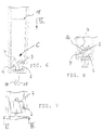
- Figures 5 to 8 show the first embodiment of the invention Device in a state C when the liquid level in the container 1 is high or when container 1 is full.
- the first embodiment of the system according to the invention according to Figures 1 to 8 essentially comprises an opaque reflection body 2 in the form of a cylinder or a roller, a light source 11 which emits a light beam in the direction of the reflection body 2 is emitted, and a light receiver 10 or light detector, receives the light radiated or reflected back by the reflection body 2.
- the reflection body 2 is arranged in a chamber 20 of a container 1, for the absorption of liquid, e.g. of ink in the case of an ink cartridge.
- the reflection body 2 is attached in the vicinity or at the bottom 8 of the container 1.
- a transparent window 9 of low thickness or thickness is provided in the bottom 8, through which the light beam from the light source 11 into the chamber 20 of the container 1 occurs and by the reflected light from the reflection body 2 from the liquid chamber 20 of the container 1 can emerge in such a way that it hits the light detector 10 falls.
- the reflection body 2 is designed in the form of a cylinder or a roller, which has a peripheral surface and two opposite end surfaces. At the A depression 21 is formed around the circumference of the cylinder or reflection body 2.
- the reflection body 2 also has two cavities 3 and 4 or chambers that extend continuously between the two end faces of the reflection body 2 and are parallel to one another and to a central axis 16 of the reflection body 2.
- the two cavities 3 and 4 have a cylindrical volume and can because they are open at the end faces, absorb liquid.
- the recess 21 of the reflection body 2 there is a reflective insert 7, e.g. made of metal, arranged and fixed, for example by gluing, the higher Density than the other cylinder.
- the recess 21 has two perpendicular ones intersecting side surfaces on which the insert 7 is seated.
- the corresponding side walls 6 and 6.1 of the insert 7 are at their end regions on the circumference of the cylinder each provided with an extension 5 on the circumference of the reflection body 2 sits on.
- the recess 21 and the insert 7 extend continuously between the two end faces of the cylinder or reflecting body 2.
- the circumference of the reflection body 2 is phased in the area outside the depression 21, that its outline in cross-section, as can be seen in Figure 1, is a regular one Represents polyhedron.
- the reflection body 2 has one on each of the two end faces Bearing journals 12 and 13, with which the reflection body 2 rotates about its central axis 16 is mounted in corresponding bearing seats 15 and 14.
- the bearing seats 15 and 14 are located at the free ends of bearing supports, which are at the bottom 8 in the Liquid chamber 20 of the container 1 are attached.
- the bearing seats 15 and 14 are designed as snap seats for the journals 12 and 13 of the reflection body 2, hold the reflection body 2 firmly when the journals 12 and 13 in the bearing seats 15 and 14 are engaged, and adjust the rotatability of the reflection body 2 its center axis 16 safely.
- Figure 8 is the mutual arrangement of the cavities 4 and 3 to the recess 21 or the insert 7 and the central axis 16 of the reflection body 2 clarified. If one starts from a fictitious plane, in which the central axis 16 of the reflection body 2 lies and the reflection body 2 in a first half and one divided second half is the recess 21 and the insert 7 and also the cavity 3 formed in a first half of the reflection body 2 while the cavity 4 in the other or second half of that divided by the fictitious level Reflection body 2 is provided.
- the cavities 3 and 4 can be more precisely such be formed so that their center axes together with the center axis 16 of the reflection body 2 lie in a further assumed level, this further fictional level is oblique to the first level and the first level in the central axis 16 of the reflection body cuts.
- the distance of the center axis of the cavity 4 to the central axis 16 is equal to the distance between the central axis of the cavity 3 and the central axis 16 of the reflection body 2.
- the light source 11 of the system according to the invention e.g. a luminescent diode be used.
- a photodetector can be used as the light receiver 10 or light detector, e.g. B. a photodiode, a pin diode or e.g. an avalanche photodiode is used become.
- the light source 11 or the light transmitter and the light detector 10 can be integrated in one unit.
- the output of the opto-electronic light detector 10 is connected to a signal shaping and evaluation electrode (not shown), which processes the signal from the light detector 10 and displays it.
- the reflection body 2 Before filling the container 1 with a liquid, e.g. Ink in the case of an ink cartridge for an ink jet printer or the like, there is the reflection body 2 in the stable position A, which is illustrated in Figures 1 and 2.
- position A that is when the container 1 is empty or empty, is the reflection body stored in the container 1 2 in a position or position in which the reflective insert 7 within the recess 21 exactly opposite the window 9 of the bottom 8 of the container 1 is aligned.
- the light beam from the light source 11 then falls after passing through through the window 9 onto the surface 6.1 of the insert 7, 90 ° on this surface 6.1 deflected to the surface 6 of the insert 7 and again from the surface 6 by 90 ° deflected and reflected towards the window 9 and thus towards the light detector 10.
- the insert 7 in the recess 21 thus acts in position A when the container is empty 1 as a deflecting mirror or deflecting reflector, the one emitted by the light source Light beam and the light beam reflected by the reflection body 2 outside the container 1 are parallel to each other.
- the reflection body 2 With increasing liquid level in the liquid chamber 20 of the container 1 the reflection body 2 begins to rotate out of the position A in FIG. 1 and takes e.g. the position B of Figures 3 and 4.
- the reason for the rotation of the reflection body 2 can be seen in the fact that the reflection body 2 as a whole is designed as a float with a resulting buoyancy.
- the interpretation the reflection body 2 as a float alone does not lead directly to a rotational movement of the reflection body 2 when the liquid level changes in the liquid chamber 20 of the container 1.
- the rotational movement due to the attacking buoyancy of the reflection body 2 is only due to an uneven or asymmetrical mass distribution of the reflection body 2 generated. This uneven Mass distribution can e.g.
- asymmetrical material accumulation can be achieved.
- the insert 7 in the recess 21 and the two cavities 3 and 4 reached that work together in such a way that the resulting one engaging the reflection body 2 Buoyancy no longer intersects the central axis 16 and thus a torque is generated, the reflection body 2 from position A (see FIG. 1) in the position B (see FIG. 3) and further to position C (see FIG. 6), which is high Level or a full container 1 shows rotates. In position C with e.g. the Level 18, the reflection body 2 is then again in a stable position.
- the second embodiment of the system according to the invention has an opaque reflection body 30 on. Furthermore, the second embodiment, like the first embodiment, has Invention according to Figure 1, a light source 11 which a light beam in the direction of Reflecting body 30 emits, and a light detector 10 by the reflecting body 30 received back radiated light.
- the reflection body 30 is again as in FIG the first embodiment in the chamber 20 of a container 1, which for Absorption of liquid, e.g. of ink, serves.
- the reflection body 30 is in the Attached or attached to the bottom 8 of the container 1.
- a transparent Window 9 is provided through which the light beam from the light source 11 into the chamber 20 of the container 1 occurs and by the reflected light from the reflection body 30 can emerge from the liquid chamber 20 of the container 1 in such a way that it acts on the Light detector 10 falls.
- the reflection body 30 is designed as a float and in the shape of the base formed of a cylinder, the one peripheral surface and two opposite Has end faces.
- the cylinder or reflection body 30 has a depression 21 with insert 7 and two cavities 3 and 4 or chambers, the elements 3, 4, 7 and 21 are formed as in the first embodiment according to FIG. 1 and also have the same functions and effects.
- the reflection body 30 has on its However, the circumference is a further depression 32, that of the depression 21 on the circumference approximately is formed opposite.
- the two inner surfaces 35 of the depression 32 extend orthogonal to each other between the two end faces of the reflection body 30. Otherwise, the peripheral surface of the reflection body 30 is in the area phased outside the recesses 21 and 32 as in the first embodiment.
- the reflection body 30 in turn has the bearing journals 12 on the two end faces or 13, with which the reflection body 30 rotatable about its central axis 31 in corresponding Bearing seats 15 and 14 is stored.
- the bearing seats 15 and 14 are located like the first embodiment on the free ends of bearing supports.
- the Elements 12 to 16 of the second embodiment have the same structure and the same characteristics as in the first embodiment.
- the fill level 33 of the liquid in container 1 is relatively low between the "full" level of position C and the "empty" level of the position A.
- the fill level 33 of position B1 can e.g. can be described as "almost empty”.
- In the stable position B1 are the center axes of the two cavities 3 and 4 and the central axis 31 of the reflection body 30 in a common plane, which is extends parallel to the bottom 8 of the container 1.
- the depression 32 of the reflection body 30 is exactly opposite to the window 9 of the container 1 in the shown Position B1 aligned.
- the two inner surfaces 35 of the recess 32 then serve to redirect the light from the light source 11 to the light detector 10 that triggered emits an electrical signal that receives the meaning Level "almost empty”.
- the evaluation electronics (not shown) connected downstream of the light detector 10 can not only because of the signals from the light detector 10 do not distinguish whether the Position A with level “empty” or position B1 with level “almost empty” is available. However, it can differentiate accordingly based on the temporal sequence of the signals the rotational movement of the reflection body 30 and thus the level change starting from position C "full” with no signal at the output of the light detector 10 via position B1 "almost empty” with a signal at the output of the light detector to position A "empty” with another signal at the output of the light detector To run.
- FIG. 11 shows a third embodiment of the invention, the following is described and explained.
- the system according to the invention has a container 40 with a bottom 51, in which a transparent, translucent window 45 is provided is, a reflection body 42 in the chamber 50 of the container 40, a light source 46, which emits light into the chamber 50, and a light detector 47, the light detected from chamber 50.
- the reflection body 42 is opaque, is designed as a float and has the shape of a cylinder with a peripheral surface and two end surfaces. On the peripheral surface is the reflection body 42 with a recess 43 with two inner surfaces provided, which extend orthogonally to one another and a reflector section or form a deflecting mirror of the reflection body 42. The inner surfaces of the depression 43 are the same size. The recess 43 extends between the end faces of the reflection body 42.
- the reflection body 42 is by means of a rigid suspension 41 with a joint 44 connected to the bottom 51 of the container 40.
- the joint 44 and the suspension 41 are shown schematically in FIG.
- the reflection body 42 thus moves up a circular path around a hinge axis of hinge 44 when the fill level of the Liquid inside the container 40 changes.
- liquid is removed from the previously full container 40, the liquid level drops in the liquid chamber 50 of the container 40 e.g. to the liquid level 48 and the reflection body 42 is then in the position F.
- Das Light that is radiated from the light source 46 into the container 40 is then from the Reflection body 42 does not reflect but rather diffusely in the liquid chamber 50 of the container 40 is distributed and absorbed such that it detects the light detector 47 not reached. No signal is then generated at the output of the light detector, what is synonymous with a fill level "full".
- the liquid level drops keeps going down and gets e.g. above level 49 at which the reflection body 42 is in position E, to the zero level at which container 40 is emptied and the reflection body 42 on the bottom 51 of the container 40 in position D rests.
- the inner surfaces of the recess 43 guide the light in position D. from the light source 46 around and reflect it back onto the photodetector 47 which is on generates an electrical signal at its output, which indicates a fill level "empty".
- FIG. 12 shows a fourth embodiment of the invention, the following is described and explained.
- the system according to the invention has one according to the invention Container 60 with a bottom 64 in which a transparent, translucent Window 65 is provided, a reflection body 61 in the liquid chamber 69 of the container 60, a light source 66 that emits light into the chamber 69 of the container 60 emits, and a light detector 67, the light from the chamber 69 and from the container 60 is detected.
- the reflection body 61 is opaque, is designed as a float and has the shape of a cuboid with an underside 61.1 that leads to the bottom 64 of the container 60 has.
- the reflection body 61 On the underside, the reflection body 61 has a depression 63 with two Inner surfaces or side surfaces that extend in a V-shape and orthogonally to one another and a reflector section or a deflecting mirror of the reflection body Train 61.
- the side surfaces of the recess 63 are of the same size.
- the deepening 63 extends continuously on the underside of the reflection body 61.
- the reflection body 61 is in a guide 62 during its movement with the liquid level guided.
- the guide 62 can e.g. be implemented as a tongue and groove system, that on two opposite sides of the reflection body 61 is arranged.
- the reflection body 61 moves linearly with the liquid level with, the recess 63 always facing the window 65 of the container 60 and the Bottom 61.1 of the reflection body 61 is parallel to the flat window 65.
- the liquid level drops in the liquid chamber 69 of the container 60 e.g. to the liquid level 68 and the reflection body 61 is then in the position G.
- Das Light from the light source 66 into the container 60 perpendicular to the transparent window 65 is irradiated, is then deflected on the inner surfaces of the reflection body 61 and thrown back to window 65.
- the light beam becomes like this in the liquid strongly attenuated that only a fraction of the light intensity generated by the light source reached the light detector 67 after the deflection.
- the one from the light detector 67 detected amount of light is e.g. so low that it is below a sensitivity threshold of the light detector 67 or below a predetermined detection threshold of Light detector 67 lies.
- the light detector 67 therefore does not output a signal, which is synonymous with level is "full".
- the liquid level drops continue until the reflection body 61 on the bottom 64 in the Liquid chamber 69 of the container 60 rests.
- the reflection body 61 is then in the position shown H and a zero level of the liquid is given at which the Container 60 is emptied.
- the orthogonal side surfaces of the recess 63 then steer in position D the light from light source 66 um and reflect it back onto the photodetector 67.
- the received light intensity lies above the detection threshold of the light detector 67, which consequently has an electrical signal at its output generated that shows a fill level "empty".
- FIG. 13 shows a fifth embodiment of the invention, the following is described and explained.
- the system according to the invention has one according to the invention Container 70 with a bottom 74 in which a transparent, translucent Window 75 with a central elevation or a centrally located projection 79, which projects into the chamber 81 of the container 70, a reflection body 71 in the chamber 81 of the container 70, a light source 76 that emits light into the Chamber 81 of the container 70 emits, and a light detector 77, the light from the Chamber 81 or detected by the container 70.
- the reflection body 71 is opaque, is designed as a float and has the shape of a cuboid with an underside 71.1 that leads to the bottom 74 of the container 70 has.
- the reflection body 71 On the underside 71.1, the reflection body 71 has a recess 73 two inner surfaces or side surfaces that are V-shaped and orthogonal to each other extend and a reflector section or deflecting reflector or a deflecting mirror form the reflection body 71.
- the side surfaces of the recess 73 are same size.
- the recess 73 extends on the underside 71.1 of the reflection body 71 continuously.
- the reflection body 71 is attached to a suspension 72, which in turn is in the upper Area of container 70, e.g. on its cover, as shown in Figure 13, or can be attached to the side walls.
- the suspension 72 can be flexible be designed so that the reflection body 71 along a straight line that is predetermined or limited by the suspension 72, with the liquid level can move.
- the suspension 72 can e.g. one or more flexible Bands or rods.
- the recess 73 of the reflection body 71 always points to the window 75 of the container 70 and the underside 71.1 of the reflection body 71 is parallel to a window 75.
- the liquid level drops in the liquid chamber 81 of the container 70 from until the Reflection body 71 hangs freely in the liquid chamber 81 of the container 70, such as e.g. with the position K of the reflection body 71 is shown in FIG.
- Position K is a distance L between the underside 71.1 of the reflection body 71 and the bottom 74 of the container 70.
- the distance L can be specified in this way be that a safe distinction between the liquid level "full” and the liquid level "empty” is made possible.
- the light on the Way to the reflection body 71 and back to the window 75 in the liquid so damped or absorbed or scattered that only a fraction of that of the Light source generated light intensity the light detector 77 after the deflection on Reflection body 71 reached.
- the light intensity detected by the light detector 77 is then e.g. so low that it is below a sensitivity threshold of the light detector 77 or below a predetermined detection threshold of the light detector 77.
- the light detector 77 therefore does not output a signal, which is synonymous with fill level is "full".
- the reflection body 71 is here in the position shown K and a zero level of the liquid is given at which the container 70 is substantially empty.
- the orthogonal side surfaces of the depression 73 then deflect the light from the position K of the reflection body 71 Light source 76 um and reflect it back onto the photodetector 77. Because the light beam inside the container 70, e.g.
- the received one Light intensity or amount of light here above the detection threshold of the light detector 77 which consequently generates an electrical signal at its output that indicates a fill level indicates "empty".
- the flat or blunt projection 79 prevents that a final residual fill level can falsify the result of the detection, since the residual liquid from the surface of the protrusion 79 into the adjacent recessed or lower lying areas has completely drained away.
- FIG. 14 shows a sixth embodiment of the invention, the following is described and explained.
- the system according to the invention has one according to the invention Container 90 with a bottom 94 in which a flat, transparent, translucent window 95 is provided, a reflection body 91 inside 99 or in a liquid chamber 99 of the container 90, a light source 96, the light emitted into the chamber 99 of the container 90, and a light detector 97, the light detected from chamber 99.
- the reflection body 91 is made of a transparent material, is a float designed and has the shape of a deflecting prism with a flat underside 91.1, which faces the bottom 94 of the container 90 and a tip which extends from the container bottom 94 or the transparent window 95.
- the reflection body 91 is in a guide 92 during its movement with the liquid level guided.
- the guide 92 can e.g. be implemented as a tongue and groove system, that on two opposite sides of the reflection body 91 is arranged.
- the reflection body 91 moves linearly or in a straight line with the Liquid level with.
- the reflection body 91 is of its volume or its Material density designed so that it is essentially in the liquid, e.g. the ink of an inkjet printer, and the two redirection points or locations of the light beam from the light source 96 on the surface of the deflection prism or the reflection body 91 are below the respective liquid level (see position O in FIG. 14).
- the refractive index of the liquid and the material of the reflection body 91 are essentially the same or matched and, if it is ink, essentially equal to the refractive index of water.
- the air in the container 90 has a significantly lower refractive index, namely the approximation Refractive index of vacuum.
- the liquid level drops in the liquid chamber 99 of the container 90 e.g. to the liquid level 98 and the reflection body 91 is then in the position O, which in 14 is shown.
- the light emitted from the light source 96 into the container 90 is irradiated perpendicular to the transparent window 95, then emerges from the surface of the transparent deflection prism at the first deflection point into the liquid and is diffusely distributed or scattered there and consequently cannot the light detector 97 achieve more.
- the light detector 97 therefore does not output a signal, which is synonymous with the fill level is "full".
- the liquid level drops continue until the reflection body 91 on the bottom 94 in the Liquid chamber 99 of the container 90 rests.
- the reflection body 91 is then in the position P shown and a zero level of the liquid is given at which the Container 90 is emptied.
- At the interface between the deflection prism and the Reflecting body 91 and the air in container 90 then becomes the light from the light source 96 deflected, namely at the two deflection points, and to the photodetector 97 thrown back, which consequently generates an electrical signal at its output, which shows a fill level "empty".
- a corresponding beam path is in the figure 14 shown for the position P.
Landscapes
- Physics & Mathematics (AREA)
- Fluid Mechanics (AREA)
- General Physics & Mathematics (AREA)
- Ink Jet (AREA)
- Level Indicators Using A Float (AREA)
Applications Claiming Priority (2)
| Application Number | Priority Date | Filing Date | Title |
|---|---|---|---|
| DE10019223A DE10019223A1 (de) | 2000-04-18 | 2000-04-18 | System zum Erfassen eines Flüssigkeitsstandes in einem Behälter |
| DE10019223 | 2000-04-18 |
Publications (2)
| Publication Number | Publication Date |
|---|---|
| EP1147902A1 true EP1147902A1 (fr) | 2001-10-24 |
| EP1147902B1 EP1147902B1 (fr) | 2007-05-09 |
Family
ID=7639203
Family Applications (1)
| Application Number | Title | Priority Date | Filing Date |
|---|---|---|---|
| EP01105355A Expired - Lifetime EP1147902B1 (fr) | 2000-04-18 | 2001-03-08 | Méthode pour détecter le niveau d'un liquide dans un réservoir |
Country Status (4)
| Country | Link |
|---|---|
| US (1) | US6554381B2 (fr) |
| EP (1) | EP1147902B1 (fr) |
| CA (1) | CA2344758A1 (fr) |
| DE (2) | DE10019223A1 (fr) |
Cited By (10)
| Publication number | Priority date | Publication date | Assignee | Title |
|---|---|---|---|---|
| EP1254775A3 (fr) * | 2001-05-01 | 2003-09-03 | Seiko Epson Corporation | Réservoir d'encre et imprimante à jet d'encre utilisant un tel réservoir |
| EP1837184A1 (fr) * | 2006-03-24 | 2007-09-26 | Brother Kogyo Kabushiki Kaisha | Cartouche d'encre ayant un élément mobile pour détecter la quantité d'encre restante |
| WO2008071279A3 (fr) * | 2006-12-12 | 2008-09-04 | Pelikan Hardcopy Production Ag | Cartouche d'encre pour imprimante à jet d'encre |
| WO2009058708A2 (fr) | 2007-10-29 | 2009-05-07 | Hewlett-Packard Development Company, L.P. | Détection de niveau d'encre par un moyen électronique |
| EP2209642A4 (fr) * | 2007-10-29 | 2010-10-20 | Hewlett Packard Development Co | Détecteur d'encre visible à l' il humain |
| EP2272674A1 (fr) * | 2009-07-06 | 2011-01-12 | Pelikan Hardcopy Production AG | Cartouche d'encre et imprimante à jet d'encre pour recevoir une telle cartouche d'encre |
| WO2011085617A1 (fr) * | 2010-01-14 | 2011-07-21 | 珠海纳思达企业管理有限公司 | Cartouche d'encre pour imprimante à jet d'encre |
| CN102218926A (zh) * | 2010-03-26 | 2011-10-19 | 兄弟工业株式会社 | 液体盒和液体供应装置 |
| CN110181946A (zh) * | 2018-02-23 | 2019-08-30 | 佳能株式会社 | 喷墨打印设备和储存器 |
| CN112161679A (zh) * | 2020-10-30 | 2021-01-01 | 阿斯曼尔科技(上海)有限公司 | 一种获取试管中液位的测量方法 |
Families Citing this family (90)
| Publication number | Priority date | Publication date | Assignee | Title |
|---|---|---|---|---|
| US6036924A (en) | 1997-12-04 | 2000-03-14 | Hewlett-Packard Company | Cassette of lancet cartridges for sampling blood |
| US6391005B1 (en) | 1998-03-30 | 2002-05-21 | Agilent Technologies, Inc. | Apparatus and method for penetration with shaft having a sensor for sensing penetration depth |
| DE10057832C1 (de) | 2000-11-21 | 2002-02-21 | Hartmann Paul Ag | Blutanalysegerät |
| US8641644B2 (en) | 2000-11-21 | 2014-02-04 | Sanofi-Aventis Deutschland Gmbh | Blood testing apparatus having a rotatable cartridge with multiple lancing elements and testing means |
| ES2336081T3 (es) | 2001-06-12 | 2010-04-08 | Pelikan Technologies Inc. | Dispositivo de puncion de auto-optimizacion con medios de adaptacion a variaciones temporales en las propiedades cutaneas. |
| US8337419B2 (en) | 2002-04-19 | 2012-12-25 | Sanofi-Aventis Deutschland Gmbh | Tissue penetration device |
| ATE497731T1 (de) | 2001-06-12 | 2011-02-15 | Pelikan Technologies Inc | Gerät zur erhöhung der erfolgsrate im hinblick auf die durch einen fingerstich erhaltene blutausbeute |
| US7041068B2 (en) | 2001-06-12 | 2006-05-09 | Pelikan Technologies, Inc. | Sampling module device and method |
| US7981056B2 (en) | 2002-04-19 | 2011-07-19 | Pelikan Technologies, Inc. | Methods and apparatus for lancet actuation |
| AU2002312521A1 (en) | 2001-06-12 | 2002-12-23 | Pelikan Technologies, Inc. | Blood sampling apparatus and method |
| US9795747B2 (en) | 2010-06-02 | 2017-10-24 | Sanofi-Aventis Deutschland Gmbh | Methods and apparatus for lancet actuation |
| CA2448681C (fr) | 2001-06-12 | 2014-09-09 | Pelikan Technologies, Inc. | Systeme integre de prelevement et d'analyse d'echantillons sanguins avec module de prelevement a utilisation multiple |
| ATE485766T1 (de) | 2001-06-12 | 2010-11-15 | Pelikan Technologies Inc | Elektrisches betätigungselement für eine lanzette |
| AU2002348683A1 (en) | 2001-06-12 | 2002-12-23 | Pelikan Technologies, Inc. | Method and apparatus for lancet launching device integrated onto a blood-sampling cartridge |
| US9427532B2 (en) | 2001-06-12 | 2016-08-30 | Sanofi-Aventis Deutschland Gmbh | Tissue penetration device |
| US9226699B2 (en) | 2002-04-19 | 2016-01-05 | Sanofi-Aventis Deutschland Gmbh | Body fluid sampling module with a continuous compression tissue interface surface |
| US7344894B2 (en) | 2001-10-16 | 2008-03-18 | Agilent Technologies, Inc. | Thermal regulation of fluidic samples within a diagnostic cartridge |
| US6769671B2 (en) * | 2002-03-01 | 2004-08-03 | Emerson Electric Co. | Device and method for indicating the amount of water contained in a humidifier water bottle |
| JP4018422B2 (ja) * | 2002-03-29 | 2007-12-05 | キヤノン株式会社 | 液体収納容器、および液体収納容器の識別方法 |
| US8702624B2 (en) | 2006-09-29 | 2014-04-22 | Sanofi-Aventis Deutschland Gmbh | Analyte measurement device with a single shot actuator |
| US7226461B2 (en) | 2002-04-19 | 2007-06-05 | Pelikan Technologies, Inc. | Method and apparatus for a multi-use body fluid sampling device with sterility barrier release |
| US7563232B2 (en) | 2002-04-19 | 2009-07-21 | Pelikan Technologies, Inc. | Method and apparatus for penetrating tissue |
| US7297122B2 (en) | 2002-04-19 | 2007-11-20 | Pelikan Technologies, Inc. | Method and apparatus for penetrating tissue |
| US7976476B2 (en) | 2002-04-19 | 2011-07-12 | Pelikan Technologies, Inc. | Device and method for variable speed lancet |
| US8267870B2 (en) | 2002-04-19 | 2012-09-18 | Sanofi-Aventis Deutschland Gmbh | Method and apparatus for body fluid sampling with hybrid actuation |
| US7331931B2 (en) | 2002-04-19 | 2008-02-19 | Pelikan Technologies, Inc. | Method and apparatus for penetrating tissue |
| US9248267B2 (en) | 2002-04-19 | 2016-02-02 | Sanofi-Aventis Deustchland Gmbh | Tissue penetration device |
| US7232451B2 (en) * | 2002-04-19 | 2007-06-19 | Pelikan Technologies, Inc. | Method and apparatus for penetrating tissue |
| US8784335B2 (en) | 2002-04-19 | 2014-07-22 | Sanofi-Aventis Deutschland Gmbh | Body fluid sampling device with a capacitive sensor |
| US7229458B2 (en) | 2002-04-19 | 2007-06-12 | Pelikan Technologies, Inc. | Method and apparatus for penetrating tissue |
| US7909778B2 (en) | 2002-04-19 | 2011-03-22 | Pelikan Technologies, Inc. | Method and apparatus for penetrating tissue |
| US7291117B2 (en) | 2002-04-19 | 2007-11-06 | Pelikan Technologies, Inc. | Method and apparatus for penetrating tissue |
| US7410468B2 (en) | 2002-04-19 | 2008-08-12 | Pelikan Technologies, Inc. | Method and apparatus for penetrating tissue |
| US7481776B2 (en) | 2002-04-19 | 2009-01-27 | Pelikan Technologies, Inc. | Method and apparatus for penetrating tissue |
| US7524293B2 (en) | 2002-04-19 | 2009-04-28 | Pelikan Technologies, Inc. | Method and apparatus for penetrating tissue |
| US7374544B2 (en) | 2002-04-19 | 2008-05-20 | Pelikan Technologies, Inc. | Method and apparatus for penetrating tissue |
| US7892183B2 (en) | 2002-04-19 | 2011-02-22 | Pelikan Technologies, Inc. | Method and apparatus for body fluid sampling and analyte sensing |
| US7547287B2 (en) | 2002-04-19 | 2009-06-16 | Pelikan Technologies, Inc. | Method and apparatus for penetrating tissue |
| US8579831B2 (en) | 2002-04-19 | 2013-11-12 | Sanofi-Aventis Deutschland Gmbh | Method and apparatus for penetrating tissue |
| US9314194B2 (en) | 2002-04-19 | 2016-04-19 | Sanofi-Aventis Deutschland Gmbh | Tissue penetration device |
| US7717863B2 (en) | 2002-04-19 | 2010-05-18 | Pelikan Technologies, Inc. | Method and apparatus for penetrating tissue |
| US7491178B2 (en) | 2002-04-19 | 2009-02-17 | Pelikan Technologies, Inc. | Method and apparatus for penetrating tissue |
| US7648468B2 (en) | 2002-04-19 | 2010-01-19 | Pelikon Technologies, Inc. | Method and apparatus for penetrating tissue |
| US9795334B2 (en) | 2002-04-19 | 2017-10-24 | Sanofi-Aventis Deutschland Gmbh | Method and apparatus for penetrating tissue |
| US7582099B2 (en) | 2002-04-19 | 2009-09-01 | Pelikan Technologies, Inc | Method and apparatus for penetrating tissue |
| US7901362B2 (en) | 2002-04-19 | 2011-03-08 | Pelikan Technologies, Inc. | Method and apparatus for penetrating tissue |
| US7371247B2 (en) | 2002-04-19 | 2008-05-13 | Pelikan Technologies, Inc | Method and apparatus for penetrating tissue |
| US7175642B2 (en) | 2002-04-19 | 2007-02-13 | Pelikan Technologies, Inc. | Methods and apparatus for lancet actuation |
| US8221334B2 (en) | 2002-04-19 | 2012-07-17 | Sanofi-Aventis Deutschland Gmbh | Method and apparatus for penetrating tissue |
| US7141058B2 (en) | 2002-04-19 | 2006-11-28 | Pelikan Technologies, Inc. | Method and apparatus for a body fluid sampling device using illumination |
| US7674232B2 (en) | 2002-04-19 | 2010-03-09 | Pelikan Technologies, Inc. | Method and apparatus for penetrating tissue |
| JP4027179B2 (ja) | 2002-08-20 | 2007-12-26 | キヤノン株式会社 | 液体収納容器、および液体収納容器内の液体量検知方法 |
| KR20040021156A (ko) * | 2002-09-02 | 2004-03-10 | 삼성전자주식회사 | 습식인쇄기의 잉크 레벨 검출장치 |
| US8574895B2 (en) | 2002-12-30 | 2013-11-05 | Sanofi-Aventis Deutschland Gmbh | Method and apparatus using optical techniques to measure analyte levels |
| EP1633235B1 (fr) | 2003-06-06 | 2014-05-21 | Sanofi-Aventis Deutschland GmbH | Appareil d'echantillonnage de fluides anatomiques et d'examen de l'analysat |
| WO2006001797A1 (fr) | 2004-06-14 | 2006-01-05 | Pelikan Technologies, Inc. | Element penetrant peu douloureux |
| US7604592B2 (en) | 2003-06-13 | 2009-10-20 | Pelikan Technologies, Inc. | Method and apparatus for a point of care device |
| DE10330093A1 (de) * | 2003-07-03 | 2005-01-20 | Robert Bosch Gmbh | Optischer Positionssensor |
| US7207666B2 (en) * | 2003-08-07 | 2007-04-24 | Hewlett-Packard Development Company, L.P. | Printer ink supply system |
| EP1671096A4 (fr) | 2003-09-29 | 2009-09-16 | Pelikan Technologies Inc | Procede et appareil permettant d'obtenir un dispositif de capture d'echantillons ameliore |
| US9351680B2 (en) | 2003-10-14 | 2016-05-31 | Sanofi-Aventis Deutschland Gmbh | Method and apparatus for a variable user interface |
| EP1706026B1 (fr) | 2003-12-31 | 2017-03-01 | Sanofi-Aventis Deutschland GmbH | Procédé et appareil permettant d'améliorer le flux fluidique et le prélèvement d'échantillons |
| US7822454B1 (en) | 2005-01-03 | 2010-10-26 | Pelikan Technologies, Inc. | Fluid sampling device with improved analyte detecting member configuration |
| US7234787B2 (en) * | 2004-01-08 | 2007-06-26 | Eastman Kodak Company | Liquid level detection method and apparatus |
| WO2006011062A2 (fr) | 2004-05-20 | 2006-02-02 | Albatros Technologies Gmbh & Co. Kg | Hydrogel imprimable pour biocapteurs |
| ES2539043T3 (es) * | 2004-06-03 | 2015-06-25 | Sanofi-Aventis Deutschland Gmbh | Interfaz de tejido en un dispositivo para la toma de muestras de fluidos |
| WO2005120365A1 (fr) | 2004-06-03 | 2005-12-22 | Pelikan Technologies, Inc. | Procede et appareil pour la fabrication d'un dispositif d'echantillonnage de liquides |
| US8652831B2 (en) | 2004-12-30 | 2014-02-18 | Sanofi-Aventis Deutschland Gmbh | Method and apparatus for analyte measurement test time |
| EP1863644A1 (fr) * | 2005-03-31 | 2007-12-12 | Seiko Epson Corporation | Conteneur ayant une fonction de detection de liquide et unite de capteur |
| US7377162B2 (en) * | 2005-06-28 | 2008-05-27 | Keurig, Incorporated | Method and apparatus for liquid level sensing |
| US7237885B1 (en) * | 2006-03-24 | 2007-07-03 | Brother Kogyo Kabushiki Kaisha | Ink cartridges |
| US7188939B1 (en) * | 2006-03-31 | 2007-03-13 | Brother Kogyo Kabushiki Kaisha | Ink cartridges |
| EP2067624B1 (fr) * | 2006-09-29 | 2011-02-16 | Brother Kogyo Kabushiki Kaisha | Cartouche de liquide et système de décharge de liquide |
| US7419254B1 (en) * | 2007-01-30 | 2008-09-02 | Brother Kogyo Kabushiki Kaisha | Ink cartridges |
| US8025378B2 (en) * | 2007-03-28 | 2011-09-27 | Brother Kogyo Kabushiki Kaisha | Ink cartridges |
| DE102007021562B4 (de) * | 2007-05-08 | 2012-05-03 | Kmp Printtechnik Ag | Tintenpatrone |
| WO2009126900A1 (fr) | 2008-04-11 | 2009-10-15 | Pelikan Technologies, Inc. | Procédé et appareil pour dispositif de détection d’analyte |
| US9375169B2 (en) | 2009-01-30 | 2016-06-28 | Sanofi-Aventis Deutschland Gmbh | Cam drive for managing disposable penetrating member actions with a single motor and motor and control system |
| US8965476B2 (en) | 2010-04-16 | 2015-02-24 | Sanofi-Aventis Deutschland Gmbh | Tissue penetration device |
| CN201816272U (zh) * | 2010-07-12 | 2011-05-04 | 珠海天威飞马打印耗材有限公司 | 喷墨打印机墨盒 |
| RU2678688C2 (ru) * | 2015-07-09 | 2019-01-30 | Общество с ограниченной ответственностью "СМП Роботикс" | Система видеонаблюдения с транспортного средства, находящегося в движении |
| JP7005989B2 (ja) * | 2017-07-28 | 2022-01-24 | 京セラドキュメントソリューションズ株式会社 | 供給液タンクユニットおよびそれを備えたインクジェット記録装置 |
| JP6958077B2 (ja) * | 2017-07-31 | 2021-11-02 | ブラザー工業株式会社 | 画像記録装置 |
| JP7062910B2 (ja) * | 2017-10-10 | 2022-05-09 | ブラザー工業株式会社 | 画像形成装置及びプログラム |
| JP7091658B2 (ja) | 2017-12-27 | 2022-06-28 | ブラザー工業株式会社 | 画像形成装置及びプログラム |
| CN109459116B (zh) * | 2018-11-05 | 2020-03-27 | 珠江水利委员会珠江水利科学研究院 | 高精度监测的水位仪 |
| CN113418581B (zh) * | 2021-05-21 | 2022-12-23 | 杭州海芯达科技有限公司 | 一种基于红外线的锅炉液位计 |
| CN113607390A (zh) * | 2021-07-01 | 2021-11-05 | 浙江意动科技股份有限公司 | 增材制造部件内部通道流体阻尼检测的设备 |
| CN114719938A (zh) * | 2022-03-30 | 2022-07-08 | 南京亚士德科技有限公司 | 一种通用车辆油量采集的装置 |
| CN220024797U (zh) * | 2023-05-04 | 2023-11-17 | 浙江比依电器股份有限公司 | 一种光电液位式感应的环岛型双箱结构 |
Citations (6)
| Publication number | Priority date | Publication date | Assignee | Title |
|---|---|---|---|---|
| JPS5774621A (en) * | 1980-10-28 | 1982-05-10 | Sharp Corp | Displacement meter |
| FR2656688A1 (fr) * | 1989-12-29 | 1991-07-05 | Jaeger | Dispositif de mesure du niveau d'un liquide dans un reservoir par determination optique de la position d'un flotteur. |
| US5054319A (en) * | 1990-09-12 | 1991-10-08 | Fling John J | Liquid level sensor and method |
| DE4217669A1 (de) * | 1992-05-28 | 1993-04-01 | Daimler Benz Ag | Vorrichtung zur fuellstandsmessung einer fluessigkeit in einem fluessigkeitsbehaelter |
| US5631674A (en) * | 1990-02-23 | 1997-05-20 | Canon Kabushiki Kaisha | Recording apparatus |
| EP0860284A2 (fr) | 1997-02-19 | 1998-08-26 | Canon Kabushiki Kaisha | Système détection de niveau de liquide, dispositif d'impression à jet de liquide et récipient de liquide |
Family Cites Families (3)
| Publication number | Priority date | Publication date | Assignee | Title |
|---|---|---|---|---|
| DE3300824C2 (de) * | 1983-01-12 | 1987-03-19 | Hans Dr. 8000 München Hofmann-Reinecke | Vorrichtung zur Messung der Höhe einer Flüssigkeitssäule |
| JPH09254405A (ja) * | 1996-03-22 | 1997-09-30 | Canon Inc | 記録装置及びその記録装置を用いたファクシミリ装置 |
| US6390590B1 (en) * | 1999-01-21 | 2002-05-21 | Oki Data Americas, Inc. | Apparatus for recording information about an ink cartridge |
-
2000
- 2000-04-18 DE DE10019223A patent/DE10019223A1/de not_active Withdrawn
-
2001
- 2001-03-08 EP EP01105355A patent/EP1147902B1/fr not_active Expired - Lifetime
- 2001-03-08 DE DE50112469T patent/DE50112469D1/de not_active Expired - Lifetime
- 2001-04-17 US US09/836,004 patent/US6554381B2/en not_active Expired - Fee Related
- 2001-04-18 CA CA002344758A patent/CA2344758A1/fr not_active Abandoned
Patent Citations (6)
| Publication number | Priority date | Publication date | Assignee | Title |
|---|---|---|---|---|
| JPS5774621A (en) * | 1980-10-28 | 1982-05-10 | Sharp Corp | Displacement meter |
| FR2656688A1 (fr) * | 1989-12-29 | 1991-07-05 | Jaeger | Dispositif de mesure du niveau d'un liquide dans un reservoir par determination optique de la position d'un flotteur. |
| US5631674A (en) * | 1990-02-23 | 1997-05-20 | Canon Kabushiki Kaisha | Recording apparatus |
| US5054319A (en) * | 1990-09-12 | 1991-10-08 | Fling John J | Liquid level sensor and method |
| DE4217669A1 (de) * | 1992-05-28 | 1993-04-01 | Daimler Benz Ag | Vorrichtung zur fuellstandsmessung einer fluessigkeit in einem fluessigkeitsbehaelter |
| EP0860284A2 (fr) | 1997-02-19 | 1998-08-26 | Canon Kabushiki Kaisha | Système détection de niveau de liquide, dispositif d'impression à jet de liquide et récipient de liquide |
Non-Patent Citations (1)
| Title |
|---|
| PATENT ABSTRACTS OF JAPAN vol. 006, no. 156 (P - 135) 17 August 1982 (1982-08-17) * |
Cited By (23)
| Publication number | Priority date | Publication date | Assignee | Title |
|---|---|---|---|---|
| EP1254775A3 (fr) * | 2001-05-01 | 2003-09-03 | Seiko Epson Corporation | Réservoir d'encre et imprimante à jet d'encre utilisant un tel réservoir |
| US6736496B2 (en) | 2001-05-01 | 2004-05-18 | Seiko Epson Corporation | Ink tank and ink-jet printer using the same |
| US6966642B2 (en) | 2001-05-01 | 2005-11-22 | Seiko Epson Corporation | Ink tank and ink-jet printer using the same |
| EP1837184A1 (fr) * | 2006-03-24 | 2007-09-26 | Brother Kogyo Kabushiki Kaisha | Cartouche d'encre ayant un élément mobile pour détecter la quantité d'encre restante |
| EP1837183A1 (fr) * | 2006-03-24 | 2007-09-26 | Brother Kogyo Kabushiki Kaisha | Cartouche d'encre adapté pour la détection de la quantité d'encre restante |
| WO2008071279A3 (fr) * | 2006-12-12 | 2008-09-04 | Pelikan Hardcopy Production Ag | Cartouche d'encre pour imprimante à jet d'encre |
| WO2009058708A2 (fr) | 2007-10-29 | 2009-05-07 | Hewlett-Packard Development Company, L.P. | Détection de niveau d'encre par un moyen électronique |
| EP2209642A4 (fr) * | 2007-10-29 | 2010-10-20 | Hewlett Packard Development Co | Détecteur d'encre visible à l' il humain |
| EP2205442A4 (fr) * | 2007-10-29 | 2012-11-28 | Hewlett Packard Development Co | Détection de niveau d'encre par un moyen électronique |
| EP2272674A1 (fr) * | 2009-07-06 | 2011-01-12 | Pelikan Hardcopy Production AG | Cartouche d'encre et imprimante à jet d'encre pour recevoir une telle cartouche d'encre |
| WO2011085617A1 (fr) * | 2010-01-14 | 2011-07-21 | 珠海纳思达企业管理有限公司 | Cartouche d'encre pour imprimante à jet d'encre |
| GB2488736A (en) * | 2010-01-14 | 2012-09-05 | Zhuhai Ninestar Man Co Ltd | Ink cartridge for inkjet printer |
| GB2488736B (en) * | 2010-01-14 | 2014-04-16 | Zhuhai Ninestar Man Co Ltd | Ink cartridge for inkjet printer |
| CN102218926A (zh) * | 2010-03-26 | 2011-10-19 | 兄弟工业株式会社 | 液体盒和液体供应装置 |
| US8469500B2 (en) | 2010-03-26 | 2013-06-25 | Brother Kogyo Kabushiki Kaisha | Liquid cartridge and liquid supplying device |
| EP2610062A1 (fr) * | 2010-03-26 | 2013-07-03 | Brother Kogyo Kabushiki Kaisha | Cartouche de liquide et dispositif d'alimentation en liquide |
| EP2368712A3 (fr) * | 2010-03-26 | 2012-10-10 | Brother Kogyo Kabushiki Kaisha | Cartouche de liquide et dispositif d'alimentation en liquide |
| US8702214B2 (en) | 2010-03-26 | 2014-04-22 | Brother Kogyo Kabushiki Kaisha | Liquid cartridge and liquid supplying device |
| CN102218926B (zh) * | 2010-03-26 | 2014-06-04 | 兄弟工业株式会社 | 液体盒和液体供应装置 |
| CN110181946A (zh) * | 2018-02-23 | 2019-08-30 | 佳能株式会社 | 喷墨打印设备和储存器 |
| US11203204B2 (en) | 2018-02-23 | 2021-12-21 | Canon Kabushiki Kaisha | Inkjet printing apparatus and tank |
| US11807018B2 (en) | 2018-02-23 | 2023-11-07 | Canon Kabushiki Kaisha | Inkjet printing apparatus and tank |
| CN112161679A (zh) * | 2020-10-30 | 2021-01-01 | 阿斯曼尔科技(上海)有限公司 | 一种获取试管中液位的测量方法 |
Also Published As
| Publication number | Publication date |
|---|---|
| US6554381B2 (en) | 2003-04-29 |
| EP1147902B1 (fr) | 2007-05-09 |
| CA2344758A1 (fr) | 2001-10-18 |
| DE50112469D1 (de) | 2007-06-21 |
| DE10019223A1 (de) | 2001-10-31 |
| US20020005869A1 (en) | 2002-01-17 |
Similar Documents
| Publication | Publication Date | Title |
|---|---|---|
| EP1147902A1 (fr) | Méthode pour détecter le niveau d'un liquide dans un réservoir | |
| DE19530281C2 (de) | Vorrichtung zum optischen Erfassen von Hindernissen vor Fahrzeugen | |
| DE102013101890B4 (de) | Optoelektronischer Sensor und Verfahren zur Bestimmung eines Füllstands eines Mediums in einem Behälter | |
| EP2604572A1 (fr) | Tête de remplissage pour remplissage de récipients | |
| DE102008017070A1 (de) | Vorrichtung zum Bestimmen einer Füllstandshöhe einer Flüssigkeit in einem Behälter | |
| DE1549000C3 (de) | Optischer Flüssigkeitsstandanzeiger | |
| DE10312100A1 (de) | Vorrichtung zur Messung eines Füllstandes einer Flüssigkeit in einem Behälter | |
| EP2565595B1 (fr) | Corps flottant pour l'affichage d'un niveau de remplissage | |
| DE3818815A1 (de) | Remissionsmessgeraet | |
| DE19819610C1 (de) | Optischer Neigungsmesser | |
| DE4217669A1 (de) | Vorrichtung zur fuellstandsmessung einer fluessigkeit in einem fluessigkeitsbehaelter | |
| DE60035826T2 (de) | Entfernungsmesser | |
| EP1943930B1 (fr) | Machine à boissons | |
| DE19709906C2 (de) | Optoelektronische Vorrichtung | |
| DE102018200363B3 (de) | Messvorrichtung zur Füllstandüberwachung und differenziellen Messung des optischen Brechungsindex | |
| DE19909068A1 (de) | Schwimmer für eine Einrichtung zum Erfassen eines Flüssigkeitspegels | |
| AT9783U1 (de) | Verfahren und vorrichtung zur optischen messung von zustandsgrössen und füllstand in einem behälter für verflüssigte gase | |
| DE102015114288A1 (de) | Verfahren und System zum Ermitteln des Füllstandes einer Flüssigkeit in einem Behälter | |
| DE3617717C2 (de) | Faseroptischer Füllstandssensor | |
| DE19756541A1 (de) | Opto-elektronischer Sensor | |
| EP2653883B1 (fr) | Capteur optique | |
| DE10360950A1 (de) | Optoelektronische Erfassungseinrichtung | |
| DE3417023C2 (de) | Sensor zum Messen des Füllstandes einer Flüssigkeit | |
| DE102021115198B4 (de) | Sicherheitsscanner | |
| EP0624229A1 (fr) | Appareil de mesure permettant d'observer le reglage du volume de deplacement de machines a pistons axiaux. |
Legal Events
| Date | Code | Title | Description |
|---|---|---|---|
| PUAI | Public reference made under article 153(3) epc to a published international application that has entered the european phase |
Free format text: ORIGINAL CODE: 0009012 |
|
| 17P | Request for examination filed |
Effective date: 20010816 |
|
| AK | Designated contracting states |
Kind code of ref document: A1 Designated state(s): AT BE CH CY DE DK ES FI FR GB GR IE IT LI LU MC NL PT SE TR Kind code of ref document: A1 Designated state(s): CH DE FR GB IT LI |
|
| AX | Request for extension of the european patent |
Free format text: AL;LT;LV;MK;RO;SI |
|
| AKX | Designation fees paid |
Free format text: CH DE FR GB IT LI |
|
| 17Q | First examination report despatched |
Effective date: 20050207 |
|
| GRAP | Despatch of communication of intention to grant a patent |
Free format text: ORIGINAL CODE: EPIDOSNIGR1 |
|
| GRAS | Grant fee paid |
Free format text: ORIGINAL CODE: EPIDOSNIGR3 |
|
| GRAA | (expected) grant |
Free format text: ORIGINAL CODE: 0009210 |
|
| AK | Designated contracting states |
Kind code of ref document: B1 Designated state(s): CH DE FR GB IT LI |
|
| REG | Reference to a national code |
Ref country code: GB Ref legal event code: FG4D Free format text: NOT ENGLISH |
|
| REG | Reference to a national code |
Ref country code: CH Ref legal event code: EP |
|
| REF | Corresponds to: |
Ref document number: 50112469 Country of ref document: DE Date of ref document: 20070621 Kind code of ref document: P |
|
| REG | Reference to a national code |
Ref country code: CH Ref legal event code: NV Representative=s name: ISLER & PEDRAZZINI AG |
|
| GBT | Gb: translation of ep patent filed (gb section 77(6)(a)/1977) |
Effective date: 20070822 |
|
| REG | Reference to a national code |
Ref country code: CH Ref legal event code: PCAR Free format text: ISLER & PEDRAZZINI AG;POSTFACH 1772;8027 ZUERICH (CH) |
|
| ET | Fr: translation filed | ||
| PLBE | No opposition filed within time limit |
Free format text: ORIGINAL CODE: 0009261 |
|
| STAA | Information on the status of an ep patent application or granted ep patent |
Free format text: STATUS: NO OPPOSITION FILED WITHIN TIME LIMIT |
|
| 26N | No opposition filed |
Effective date: 20080212 |
|
| REG | Reference to a national code |
Ref country code: CH Ref legal event code: PL |
|
| GBPC | Gb: european patent ceased through non-payment of renewal fee |
Effective date: 20080308 |
|
| REG | Reference to a national code |
Ref country code: FR Ref legal event code: ST Effective date: 20081125 |
|
| PG25 | Lapsed in a contracting state [announced via postgrant information from national office to epo] |
Ref country code: LI Free format text: LAPSE BECAUSE OF NON-PAYMENT OF DUE FEES Effective date: 20080331 Ref country code: CH Free format text: LAPSE BECAUSE OF NON-PAYMENT OF DUE FEES Effective date: 20080331 |
|
| PG25 | Lapsed in a contracting state [announced via postgrant information from national office to epo] |
Ref country code: FR Free format text: LAPSE BECAUSE OF NON-PAYMENT OF DUE FEES Effective date: 20080331 |
|
| PG25 | Lapsed in a contracting state [announced via postgrant information from national office to epo] |
Ref country code: GB Free format text: LAPSE BECAUSE OF NON-PAYMENT OF DUE FEES Effective date: 20080308 |
|
| PG25 | Lapsed in a contracting state [announced via postgrant information from national office to epo] |
Ref country code: IT Free format text: LAPSE BECAUSE OF NON-PAYMENT OF DUE FEES Effective date: 20080308 |
|
| REG | Reference to a national code |
Ref country code: DE Ref legal event code: R084 Ref document number: 50112469 Country of ref document: DE Effective date: 20120703 |
|
| PGFP | Annual fee paid to national office [announced via postgrant information from national office to epo] |
Ref country code: DE Payment date: 20130320 Year of fee payment: 13 |
|
| REG | Reference to a national code |
Ref country code: DE Ref legal event code: R119 Ref document number: 50112469 Country of ref document: DE |
|
| REG | Reference to a national code |
Ref country code: DE Ref legal event code: R119 Ref document number: 50112469 Country of ref document: DE Effective date: 20141001 |
|
| PG25 | Lapsed in a contracting state [announced via postgrant information from national office to epo] |
Ref country code: DE Free format text: LAPSE BECAUSE OF NON-PAYMENT OF DUE FEES Effective date: 20141001 |